Facebook Instagram Youtube Twitter

Thermal Storage System | Capacity & Benefits

Learn about thermal storage systems, their types, capacity, and benefits in energy efficiency and sustainability.
Thermal Storage System | Capacity & Benefits

Understanding Thermal Storage Systems: Capacity and Benefits

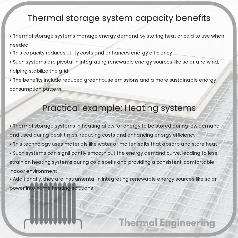
Thermal storage systems are an innovative engineering solution that store thermal energy for later use, either for heating or cooling applications. These systems are critical components in improving the efficiency of energy usage and supporting sustainable practices in various industries. In this article, we’ll explore the capacity of thermal storage systems and their myriad benefits.

Types of Thermal Storage Systems

There are three primary types of thermal storage systems, each based on the way they store heat:

  • Sensible Heat Storage: Utilizes the physical properties of a medium, such as water or sand, to store heat. The energy is stored by raising the temperature of the medium.
  • Latent Heat Storage: Involves materials, known as phase change materials (PCMs), that absorb or release heat as they change phase (e.g., from solid to liquid).
  • Thermochemical Heat Storage: Incorporates chemical reactions to store and release heat, which can be very efficient as it involves minimal loss of energy over time.

Capacity of Thermal Storage Systems

Capacity typically refers to the amount of energy a system can store and release. It is often measured in kilowatt-hours (kWh) or megawatt-hours (MWh). The actual capacity of a thermal storage unit depends largely on the type of storage method and the materials used:

  • In sensible heat storage, the capacity can be determined by the equation:

    Q = m * c * ΔT

    where Q is the thermal energy stored (in Joules), m is the mass of the storage medium (in kilograms), c is the specific heat capacity of the medium (J/kg·K), and ΔT is the temperature change of the medium (in Kelvin).

  • In latent heat storage, the energy capacity is primarily influenced by the latent heat of fusion or vaporization of the phase change material. The energy stored (Q) can be expressed as:

    Q = m * L

    where L is the latent heat of the material (J/kg).

For thermochemical storage, the capacity can be much higher than sensible and latent systems as it is based on the energy changes from chemical reactions, which can store heat indefinitely with minimal losses.

Benefits of Thermal Storage Systems

Thermal storage systems offer a range of benefits:

  • Energy Efficiency: They can help reduce energy consumption and peak demand charges by allowing industrial and residential users to store excess energy produced during off-peak times and use it during peak hours.
  • Rrenewable Energy Integration: These systems are ideal for smoothing out the supply of renewable energy sources, such as solar or wind, which are not consistent throughout the day.
  • Cost-Effectiveness: By balancing supply and demand, thermal storage systems can significantly lower heating and cooling costs over time.
  • Environmental Impact: They can reduce greenhouse gas emissions by optimizing the energy production from renewable sources and decreasing reliance on fossil-fueled power plants.
  • Versatility: Thermal storage can be used in a variety of applications, from large-scale industrial processes to residential heating and cooling systems.

In conclusion, thermal storage systems, with their efficient and versatile energy storage capabilities, present an essential solution in the modern landscape of energy management and sustainability. Whether through sensible, latent, or thermochemical means, these systems harness the potential to revolutionize how we use and conserve energy across sectors.
Impulse Steam Turbine | Efficiency, Applications

Learn about impulse steam turbines, their operation, efficiency, and diverse applications in industries such as power generation and aerospace.

Impulse Steam Turbine | Efficiency, Applications

Understanding the Impulse Steam Turbine: Efficiency and Applications

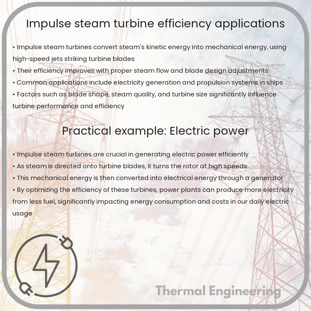
An impulse steam turbine is a type of steam turbine where the rotor gets its energy from the kinetic energy of the steam at high velocity. Unlike reaction turbines that use both the energy from the pressure and velocity of the steam, impulse turbines solely depend on the kinetic energy transformed from the steam’s pressure. This fundamental principle behind the impulse steam turbine plays a significant role in its construction, efficiency, and applications.

Principle of Operation

In an impulse steam turbine, steam is initially pressurized in a boiler and then directed onto turbine blades through a nozzle. As steam passes through these nozzles, it expands, speeds up to a high velocity, and jets out against the turbine blades. The interaction of steam with the turbine blades converts the kinetic energy of the steam to mechanical energy, thereby rotating the turbine shaft. This conversion underscored by the conservation of momentum, fundamentally describes the operating principle of an impulse steam turbine.

Mathematically, the change in momentum of the steam generates a force on the turbine blades as illustrated by the equation:

F = Δ(mv)

where F represents the force exerted on the blades, m is the mass of the steam, and v is the velocity of the steam. The steam’s velocity transformation through the nozzles and the resultant force produced is crucial for achieving the turbine’s rotational movement.

Efficiency of Impulse Steam Turbines

The efficiency of an impulse steam turbine mainly depends on how effectively it can convert the steam’s kinetic energy into mechanical energy. Factors that affect its efficiency include the design of the turbine, such as the shape and arrangement of the nozzles and blades, steam conditions (pressure and temperature), and the load conditions under which the turbine operates. Losses in efficiency mainly arise from:

  • Nozzle efficiency: This refers to the effective conversion of thermal energy into kinetic energy in the nozzles. Inadequate design can lead to significant energy losses.
  • Blade friction and windage: As the steam interacts with the turbine blades, friction between the blade surfaces and the steam leads to energy losses.
  • Profile losses: Caused by the aerodynamic design of the blades which can lead to turbulence and vortices reducing the turbine’s efficiency.
  • Other mechanical and thermodynamic losses: Such as leakage in the seals, bearing friction, and entropy production during steam expansion.

Overall, improvements in blade geometry and nozzle design, along with optimal control of steam conditions, help in minimizing these losses thereby maximizing the turbine’s efficiency. The efficiency of impulse steam turbines typically ranges, but it is generally less than that of reaction turbines given the conservation restrictions primarily at higher pressure operations.

Applications of Impulse Steam Turbines

Impulse steam turbines are widely used across various sectors due to their robust design and ability to handle high-pressure gradients efficiently. Their applications include:

  • Power Generation: Most commonly used in electricity generation from nuclear, coal, natural gas, and biomass power plants.
  • Marine Propulsion: Used in marine vessels for propulsion systems where high-speed rotation is essential.
  • Industrial Processes: Applied in industries for driving centrifugal pumps, fans, compressors, and other machinery.
  • Aerospace: Utilized in jet engines where high-speed exhaust is necessary for propulsion.

In summary, impulse steam turbines are a pivotal engineering tool in many modern applications. Their ability to convert steam’s kinetic energy into mechanical work efficiently, despite inherent energy losses, plays a crucial role in the realms of power generation and beyond. Continuous advancements in turbine technology focus on enhancing their design and operational efficiency to meet the increasing energy demands and environmental standards.

Shell & Tube Heat Exchanger | Durability & Applications

Learn about the design, durability, and diverse applications of shell and tube heat exchangers in various industries.

Shell & Tube Heat Exchanger | Durability & Applications

Understanding the Shell & Tube Heat Exchanger: Durability and Applications

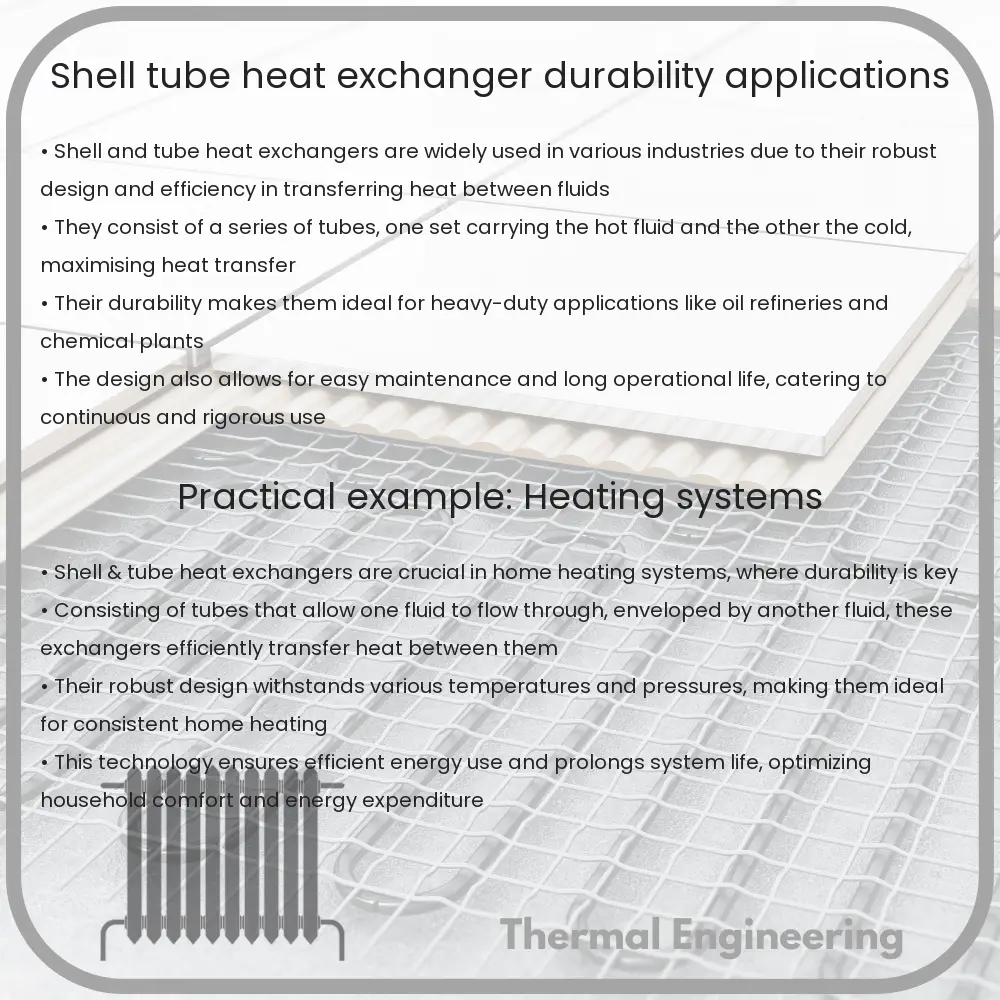
Shell and tube heat exchangers are a staple in various industries, serving as critical components in the processes of heating, cooling, and exchanging heat between fluids. Known for their robust structure and efficient heat transfer capabilities, these exchangers play a pivotal role in manufacturing, power generation, and even in the processing of chemicals.

Design and Durability of Shell & Tube Heat Exchangers

The fundamental structure of a shell and tube heat exchanger consists of a series of tubes, which one set of fluids travels through, and a shell that encloses these tubes, allowing another fluid to flow around the tube bundle. This construction not only facilitates efficient thermal exchange but also contributes significantly to the device’s durability:

  • Material Selection: Shell and tube exchangers are typically made from robust materials like stainless steel, titanium, and copper alloys. These materials are chosen for their ability to withstand high temperatures, pressures, and corrosive substances.
  • Tube Design: The tubes can be seamless or welded, each offering different advantages in terms of strength and resistance to leakage. Tube thickness and diameter are also tailored to meet specific operational demands and lifespan requirements.
  • Corrosion Resistance: Corrosion is a major concern in heat exchangers, affecting their longevity and efficiency. Many shell and tube exchangers feature corrosion-resistant coatings or are constructed from specialty alloys to combat this issue.
  • Maintenance: Easy access to the interior for cleaning and maintenance also enhances the durability of these systems. Many heat exchangers are designed with removable tube bundles or segmented shells that simplify routine inspections and repairs.

Applications of Shell & Tube Heat Exchangers

Thanks to their adaptability and efficiency, shell and tube heat exchangers are utilized in a broad array of applications:

  1. Power Generation: They are crucial in power plants for condensing steam into water in steam turbines and for cooling power generation equipment.
  2. Chemical Processing: In chemical plants, these exchangers are used to maintain the temperatures of chemically reactive substances at safe and effective levels.
  3. Oil Refineries: Shell and tube exchangers play a central role in the heating and cooling processes crucial for separating crude oil into various fractions.
  4. Marine Applications: These devices are used to cool engines and various shipboard systems, ensuring efficient operation in harsh marine environments.
  5. Food and Beverage Industry: They regulate temperatures during processes such as pasteurization and fermentation, which are essential for product quality and safety.

Shell and tube heat exchangers are thus fundamental to the smooth operation and efficiency of systems across various industries. Their ability to operate under harsh conditions, combined with their versatility in handling different fluids, makes them indispensable in both industrial and commercial applications. The ongoing improvements in materials science and thermal engineering continue to enhance the performance and durability of these essential devices.

In conclusion, the durability and broad application spectrum of shell and tube heat exchangers underscore their importance in modern engineering. Whether it’s maintaining the perfect temperature for chemical reactions or ensuring machinery operates smoothly, these heat exchangers are at the heart of many critical industrial processes.

Cooling Tower | Principles & Sector Operation

Explore the principles, types, and sector-specific applications of cooling towers, critical for industrial temperature regulation.

Cooling Tower | Principles & Sector Operation

Understanding Cooling Towers: Principles and Sector Operations

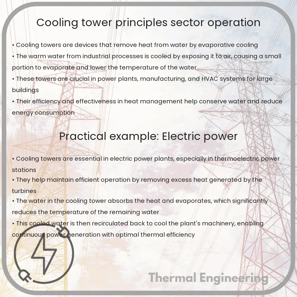
Cooling towers are essential components in a variety of industrial processes where they are utilized to dissipate heat into the atmosphere. They are commonly found in power plants, manufacturing facilities, and HVAC systems for large buildings. This article will explore the basic principles of cooling tower operation and how they are implemented in different sectors.

The Basic Principle of Cooling Towers

Cooling towers operate on the principle of heat rejection. They remove waste heat from a process or building and release it into the atmosphere primarily through the process of evaporation. A cooling tower receives warm water from the process it is cooling, which gets cooled down as it passes through the tower and is sent back to the process. This circulation cycle helps in maintaining a balanced temperature that is crucial for industrial processes and effective air conditioning.

Types of Cooling Towers

  • Mechanical Draft Towers: These towers use power-driven fans to force or draw air through the tower. They are further divided into forced draft and induced draft cooling towers.
  • Natural Draft Towers: Utilize the natural buoyancy of hot air to facilitate airflow through the cooling tower, thus eliminating the need for mechanical fans. These towers are typically much larger in size and commonly used in power generation sectors.

Key Components of a Cooling Tower

  • Water Basins: Collect the cooled water at the bottom of the tower to be recirculated back into the system.
  • Fill Material: Increases the surface area for heat transfer between the air and the water. The fill can be either splash type, which breaks the water and promotes air interaction, or film type, where water spreads into a thin film.
  • Distribution Systems: These systems evenly distribute hot water over the fill media to optimize cooling.
  • Fans: In mechanical draft towers, fans are used to move air through the tower.
  • Drift Eliminators: Reduce the amount of water droplets and vapor carried away by the process air.

How Cooling Towers Work

The operation of a cooling tower starts when warm water from the process (often the return from a heating or cooling system) is piped into the tower. Once inside, the water is distributed over the fill material, facilitating heat transfer through direct contact or evaporation. As the water travels down the fill, it cools down through evaporation, which removes the heat from the water. The cooled water is then collected in basins at the bottom of the tower and recirculated into the process. Simultaneously, air is either pulled or pushed by fans (in mechanical draft towers) or flows naturally (in natural draft towers) through the fill to further facilitate the cooling through convective heat transfer.

Cooling Tower Efficiency

The efficiency of a cooling tower depends on various factors such as the wet-bulb temperature, the type and condition of the fill, air and water flow rates, and overall operational maintenance. By optimizing these factors, the efficiency of cooling towers can substantially increase, leading to better temperature regulation and reduced energy consumption.

Sector-Specific Applications

  1. Power Generation: Cooling towers in power plants help in maintaining the low temperature of the condensing steam.
  2. Industrial Processing: Many manufacturing processes need controlled temperatures to ensure product quality, and cooling towers provide this feature efficiently.
  3. HVAC Systems: Major commercial buildings use cooling towers to dissipate heat from the building’s air conditioning system, maintaining a comfortable indoor environment.

In conclusion, cooling towers are vital for numerous applications across different sectors, significantly impacting operational efficiencies and environmental control. By understanding the principles on which these towers operate, industries can tailor their use to meet specific cooling needs effectively.

Waste heat recovery systems

Learn about Waste Heat Recovery Systems (WHRS), their function, benefits, types, and the engineering challenges they address in industrial efficiency.

Waste heat recovery systems

What Are Waste Heat Recovery Systems?

Waste heat recovery systems (WHRS) are crucial in engineering, designed to capture and reuse the heat from various industrial processes that would otherwise be wasted. These systems significantly increase energy efficiency, reduce energy costs, and decrease overall greenhouse gas emissions. Typically used in large-scale facilities such as power plants, manufacturing plants, and large ships, waste heat recovery is an important strategy in achieving sustainable development.

How Do Waste Heat Recovery Systems Work?

Waste heat recovery systems function by capturing the excess heat generated during industrial processes. This heat, which might emanate from equipment or the process itself, can be transformed to serve other useful purposes. The process involves several key components:

  • Heat Exchanger: A device that transfers heat from the waste stream to a working fluid (such as water or oil) without direct contact between the two fluids.
  • Recovery Unit: The section of the system where the captured heat is converted into usable heat, electricity, or mechanical power.
  • Conversion System: This includes turbines and generators that convert thermal energy into electricity or mechanical devices, depending on the configuration.

The most common applications of WHRS include pre-heating combustion air for boilers, powering steam generators to produce electricity, and as supplemental energy sources for space heating or other industrial processes.

Types of Waste Heat Recovery Systems

Different forms of waste heat recovery systems are tailored to fit various industrial processes, based on the quality and temperature of the waste heat produced:

  • Regenerators: This type involves storing heat in a thermal storage medium to be recovered as needed.
  • Recuperators: Direct heat exchange systems where waste heat is transferred directly to the working fluid.
  • Waste Heat Boilers: These are steam boilers that use waste heat to produce steam for heating or power generation.
  • Thermoelectric Generators: Convert heat directly into electricity through a phenomenon called the Seebeck effect.
  • Organic Rankine Cycle (ORC): Using organic fluids to run turbines instead of water steam, these systems operate effectively at lower temperatures.

Benefits of Waste Heat Recovery

Implementing waste heat recovery systems offers numerous benefits:

  • Energy Cost Reduction: By reusing waste heat, the need for additional fuel is reduced, thus lowering energy costs.
  • Increased Efficiency: WHRS increase the overall efficiency of the energy usage process, as less energy is wasted.
  • Reduced Environmental Impact: By minimizing the release of burned fuel byproducts like CO2, NOx, and SOx, these systems help in reducing environmental pollution.
  • Enhanced System Lifespan: Utilizing waste heat can lead to lower operational temperatures and stress in systems, contributing to a longer operational lifespan and reduced maintenance costs.

Challenges in Waste Heat Recovery

Despite the apparent benefits, there are several challenges in implementing waste heat recovery systems:

  • High Upfront Costs: Installing WHRS requires significant capital investment which can be a barrier for some industries.
  • Complexity in Integration: Retrofitting existing systems with WHRS can require significant engineering challenges and space considerations.
  • Maintenance: Keeping the system efficient requires adequate maintenance practices, which may increase operational costs.
  • Dependence on Process Heat: The efficiency of a WHRS highly depends on the temperature and quality of waste heat, which might not be constant.

Despite these challenges, the push towards sustainable and efficient energy use makes waste heat recovery systems a vital component of modern industrial processes. By improving the adoption of such technologies, industries can significantly contribute to global energy efficiency and environmental protection goals.

Plate Heat Exchanger | Performance & Uses

Learn about plate heat exchangers, their efficient heat transfer, structure, performance factors, and diverse industrial applications.

Plate Heat Exchanger | Performance & Uses

Understanding Plate Heat Exchangers: Performance and Uses

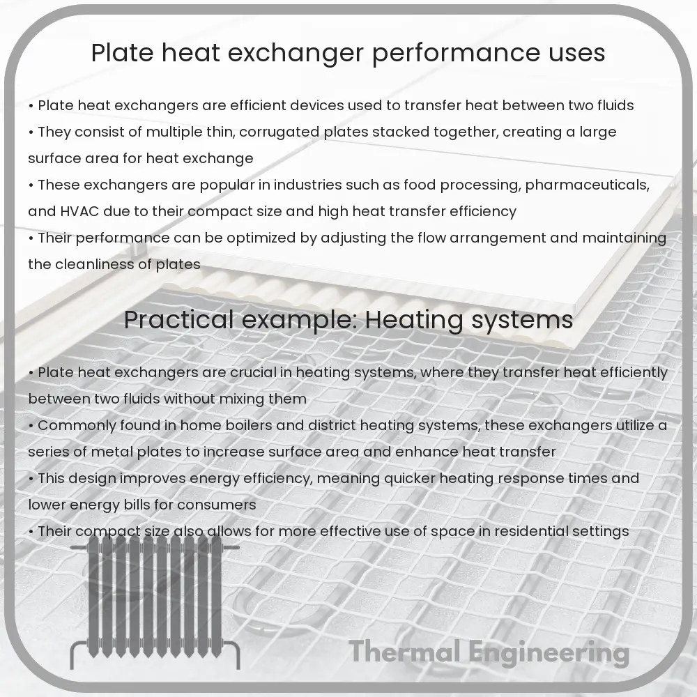
Plate heat exchangers are sophisticated devices designed to transfer heat between two or more fluids efficiently. They are widely known for their high heat transfer efficiency, compact structure, and versatility in various applications. This article explores the performance characteristics and uses of plate heat exchangers.

Structure and Working Principle

A plate heat exchanger consists of multiple thin, corrugated plates assembled at a fixed distance. Each alternate space between the plates forms a channel for one of the fluids to flow through, while the second fluid flows through the other channels. The corrugated pattern not only strengthens the plates but also promotes turbulent flow, enhancing the heat transfer efficiency.

The plates are usually made of stainless steel or titanium, which gives them high thermal conductivity and resistance to corrosion. The edges of the plates are sealed with gaskets, which direct the fluids into alternating channels and prevent them from mixing.

Performance Factors

The performance of a plate heat exchanger is influenced by several factors:

  • Plate design: The design of the plates, including their size, thickness, and corrugation pattern, affects the turbulent flow and surface area available for heat transfer.
  • Material: The thermal conductivity of the plate material is crucial because higher conductivity facilitates a more efficient heat transfer.
  • Flow arrangement: Plate heat exchangers can operate in counterflow or co-current arrangements. Counterflow is typically more efficient because it can achieve a higher log mean temperature difference (LMTD).

The efficiency of a plate heat exchanger can be evaluated using its overall heat transfer coefficient (U), which is defined by the equation:

\[ U = \frac{Q}{A \times \Delta T_{lm}} \]

Here, Q is the rate of heat transfer, A is the heat transfer area, and \Delta T_{lm} is the log mean temperature difference between the two fluids.

Common Uses of Plate Heat Exchangers

Thanks to their efficient heat transfer and compact size, plate heat exchangers are employed in a variety of industries:

  1. Food and Beverage: Used for cooling or heating products like milk, beer, and juices to ensure safety and quality through pasteurization and other processes.
  2. Chemical Processing: Employed in the heating or cooling of chemicals, which is crucial for the vast array of chemical reactions that occur in the industry.
  3. Power Generation: Used in power plants to cool the working fluids in turbines and as interchangers in cogeneration plants where waste heat is reused.
  4. Marine Applications: Integral in managing engine coolant and refrigerating systems on ships, minimizing energy consumption and enhancing operational efficiency.

Conclusion

Plate heat exchangers are fundamental components in many industrial applications due to their efficient heat transfer capabilities, adaptability to different environments, and relatively low maintenance requirements. Understanding their mechanics and applications helps industries optimize thermal processes and contribute to energy conservation efforts.

This insight into the performance and uses of plate heat exchangers reveals why they are a preferred choice in various sectors and highlights their significance in modern engineering solutions.

Evaporative Cooler | Benefits & Operation

Learn about evaporative coolers, their efficient cooling method, practical benefits, and ideal operating conditions.

Evaporative Cooler | Benefits & Operation

Understanding Evaporative Coolers: Benefits and Operation

Evaporative coolers, also known as swamp coolers, offer a simple, cost-effective method of cooling indoor spaces. This device operates on the principle of evaporation and is particularly effective in hot, dry climates. In this article, we will explore how evaporative coolers work and discuss their advantages.

How Does an Evaporative Cooler Work?

Evaporative cooling is based on the concept of water evaporation. It involves the process of transforming liquid water into vapor using thermal energy in the air, thereby reducing the temperature of the air.

The central components of an evaporative cooler are:

  • Cooling pads: These pads are generally made from wood shavings, cellulose, or other materials that absorb and hold water. As air passes through these wet pads, it cools down.
  • Water tank: Holds the water needed to keep the pads saturated.
  • Fan: Pulls the hot, dry external air through the moist pads, facilitating the cooling process before circulating the cooled air throughout the space.
  • Pump: Circulates water from the tank to the pads.

The operation can be summarized in three steps:

  1. Water is pumped from the tank to continuously saturate the cooling pads.
  2. Air is drawn into the cooler through the damp pads where it loses heat as some of the water in the pads evaporates.
  3. The fan then pushes the cooled air out into the room or designated area, lowering the overall temperature.

Benefits of Evaporative Coolers

Evaporative coolers offer several benefits over traditional air conditioning systems, making them a preferred choice in suitable environments:

  • Energy Efficiency: These coolers use significantly less electricity than conventional air conditioners, primarily because they have fewer mechanical components and use water as the cooling medium. This can lead to substantial energy savings, especially in hot, dry climates where they are most effective.
  • Cost-Effective: Lower energy consumption translates to lower utility bills. Additionally, evaporative coolers generally have lower installation and maintenance costs.
  • Eco-Friendly: Unlike traditional air conditioning systems that utilize refrigerants, which can be harmful to the environment, evaporative coolers use water, making them more sustainable and environmentally friendly.
  • Adds Moisture to the Air: Instead of drying out the air like conventional air conditioning, evaporative coolers increase indoor humidity, which can be beneficial in arid climates.
  • Simple Maintenance: With fewer mechanical parts than traditional AC systems, evaporative coolers are generally easier and less expensive to maintain.

Optimal Environments for Evaporative Coolers

While evaporative coolers are advantageous under the right conditions, they are not suitable for all climates. They are most effective in areas with low humidity levels, where the air has a higher capacity to absorb water vapor. High humidity conditions inhibit the evaporation process, reducing the cooling efficiency of the device. Therefore, regions with dry air, such as many areas in the southwestern United States, are ideal for evaporative cooling systems.

In conclusion, evaporative coolers provide a cost-efficient and environmentally friendly alternative for cooling spaces in appropriate climates. Understanding the operation and benefits of these devices can help individuals and businesses make informed decisions about their cooling needs, potentially reducing their environmental footprint while staying comfortable economically.

Crossflow Heat Exchanger | Features & Industries

Learn about crossflow heat exchangers, their design, efficiency, and applications in various industries like HVAC and power generation.

Crossflow Heat Exchanger | Features & Industries

Understanding Crossflow Heat Exchangers

A crossflow heat exchanger is a vital component widely used in various industrial and heating, ventilation, and air conditioning (HVAC) applications. This type of heat exchanger allows two fluids of different temperatures to cross paths, typically perpendicular to each other, facilitating the transfer of heat without mixing the fluids directly.

Key Features of Crossflow Heat Exchangers

The primary characteristic of a crossflow heat exchanger is the perpendicular flow of the two fluids involved. Below are some notable features:

  • Compact Design: Crossflow heat exchangers are designed to maximize the surface area for heat transfer while minimizing the volume occupied, making them ideal for use in space-constrained environments.
  • Efficient Heat Transfer: This type of exchanger is particularly efficient at transferring heat from one fluid to another, thanks to the high surface area to volume ratio.
  • Modular Nature: Crossflow heat exchangers can be easily scaled up or down by adding or removing modules, making them versatile for different industrial applications.
  • Low Maintenance: The design minimizes maintenance requirements since the fluids usually don’t mix, reducing contamination risks and the associated cleaning needs.

Thermal Performance Equation

The effectiveness (ε) of a crossflow heat exchanger, which is not mixed, can be approximated using the equation:

\[ \epsilon = 1 – e^{-NTU^\frac{2}{3}} \]

Where NTU (Number of Transfer Units) is calculated as:

\[ NTU = \frac{(UA)}{C_{min}} \]

Here, U is the overall heat transfer coefficient, A is the surface area for heat exchange, and Cmin represents the minimum heat capacity rate of the two fluids.

Common Applications in Industries

Crossflow heat exchangers are extensively applied across diverse industries. Some key applications include:

  • Power Generation: They are used in power plants to cool the working fluids used in turbines and generators.
  • Automotive: Utilized in the cooling of engine components and in air conditioning systems within vehicles.
  • Chemical Processing: Important for controlling the temperatures of chemical reactions, which is crucial for product quality and safety.
  • Pharmaceutical: Used in the manufacturing process to maintain precise temperature conditions vital for drug formulation and safety.
  • HVAC Systems: Central to the efficiency of residential and commercial air conditioning units, helping in the management of indoor air temperatures.

Advancements in materials and technology continue to enhance the performance and efficiency of crossflow heat exchangers, making them integral to modern industrial operations and everyday appliances.

Conclusion

Crossflow heat exchangers play an essential role in managing thermal energy in a variety of industrial applications. Their design and operational efficiency make them suitable for many scenarios where effective heat transfer is necessary. As technology progresses, these devices continue to evolve, enhancing their capability to meet the growing demands of modern industry and technology.

Oil Water Separator | Environmental Compliance & Separation

Learn about oil water separators (OWS), essential devices for removing oils from wastewater to meet environmental standards and protect ecosystems.

Oil Water Separator | Environmental Compliance & Separation

Understanding Oil Water Separators for Environmental Compliance

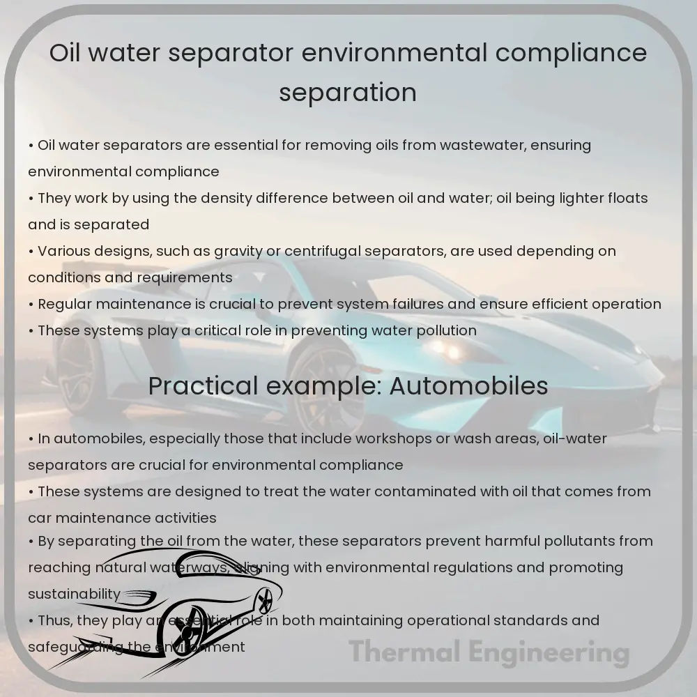
Oil water separators (OWS) are critical devices used to ensure that wastewater and stormwater discharges meet environmental standards, primarily by removing oils and other hydrocarbons. These systems are essential in preventing pollutants from entering water bodies, thus protecting ecosystems and complying with regulations. This article explores the basic function, types, and key considerations associated with oil water separators.

How Oil Water Separators Work

The primary function of an oil water separator is to separate oil and other hydrophobic substances from water. These systems utilize the differences in density between oil and water. Oil, having a lower density than water, floats to the surface. The basic operational steps in an oil water separator are typically as follows:

  • Influent: Wastewater containing oil enters the separator.
  • Separation Chamber: As the wastewater slows down in this chamber, oil droplets begin to coalesce (combine) and rise to the surface due to gravity.
  • Oil Removal: The accumulated oil is skimmed off the top, leaving behind cleaner water.
  • Effluent: The treated water is discharged, now largely free from oil.

Types of Oil Water Separators

Several types of oil water separators are used in different applications, each suited to specific needs:

  1. Gravity Separators: These are the simplest form, relying on gravity to separate oil from water. They are effective where large volumes of oil need to be removed, under low-flow conditions.
  2. Coalescing Plate Separator (CPS): In CPS, special plates are used to increase the surface area, improving the efficiency of oil separation. They are well-suited for high-efficiency removal of small oil droplets.
  3. Hydrocyclone Separators: These use centrifugal force to separate oil from water. Hydrocyclone separators are effective in removing fine oil droplets and are often used in intense industrial applications.

Key Considerations in Oil Water Separator Design

When designing or selecting an oil water separator, several factors must be considered to ensure effective operation. Some of these include:

  • Flow Rate: The maximum and minimum flow rates can significantly affect the performance of the separator. System sizing should accommodate fluctuations in flow rate.
  • Oil Load: The type and concentration of oil in the influent water affect the choice of separator. Heavier oil loads may require more robust systems.
  • Maintenance: Regular maintenance is crucial for ensuring long-term performance and compliance. This includes skimmer maintenance, chamber cleaning, and visual inspections.
  • Regulatory Standards: Compliance with local, state, and federal regulations is a must. Regulations may dictate specific performance standards or technology types.

Environmental Impact and Compliance

Properly functioning oil water separators are vital for protecting water quality. By removing harmful pollutants, these systems help prevent contamination of drinking water sources, aquatic habitats, and recreational waters. Compliance with environmental regulations not only helps protect natural ecosystems but also shields businesses from legal penalties and potential damage to reputation.

In conclusion, oil water separators are essential tools in environmental protection, ensuring that discharges meet regulatory standards and protecting water quality. Understanding their operation, types, and design considerations is crucial for anyone involved in handling wastewater treatment or stormwater management.

Finned Tube Heat Exchanger | Advantages & Applications

Learn how a finned tube heat exchanger increases efficiency and versatility in heating and cooling applications across various industries.

Finned Tube Heat Exchanger | Advantages & Applications

Finned Tube Heat Exchanger: Understanding its Advantages and Applications

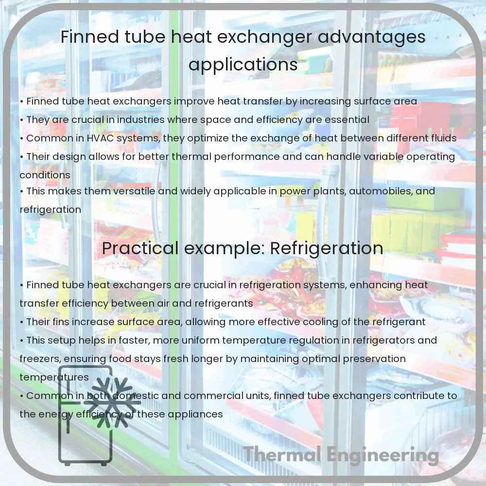
A finned tube heat exchanger is a type of engineering device designed to efficiently transfer heat between two or more fluids, gases, or vapors. This type of heat exchanger utilizes fins or extended surfaces attached to the tube carrying the heat transfer fluid. The fins increase the external surface area of the tube, enhancing the heat exchange process by facilitating a higher rate of heat transfer compared to a plain tube.

How does a Finned Tube Heat Exchanger Work?

In a finned tube heat exchanger, tubes with extended outer surfaces or fins are mounted inside a shell. One fluid flows through the tubes and the other fluid flows outside the tubes but inside the shell. Heat is transferred from the hotter fluid to the cooler fluid through the walls of the tubes and the attached fins. The presence of fins increases the surface area that is in contact with the fluid outside the tubes, accelerating the heat transfer process.

Advantages of Finned Tube Heat Exchangers

  • Increased Efficiency: The fins provide additional surface area, which increases the heat transfer rate. This makes finned tube heat exchangers more efficient especially in applications involving gases where the heat transfer coefficient is relatively low.
  • Compact Size: Due to the enhanced heat transfer effectiveness, finned tube heat exchangers can be designed smaller than their unfinned counterparts while delivering the same performance. This reduction in size is crucial for applications where space is a premium.
  • Flexibility in Applications: Different types and arrangements of fins allow these heat exchangers to be tailored for specific fluids and flow conditions, enhancing their versatility across various industries.
  • Cost-Effective: Despite the higher initial cost compared to plain tube heat exchangers, the improved heat transfer efficiency can lead to significant savings in operational costs over time.
  • Resistance to fouling: Due to the increased turbulence created by the fins, there is a reduction in the buildup of deposits on the tube surface, which helps in maintaining efficiency and reducing maintenance costs.

Applications of Finned Tube Heat Exchangers

  • HVAC Systems: Utilized extensively in heating, ventilation, and air conditioning systems for efficient heat transfer.
  • Power Plants: Employed in power plants for waste heat recovery and to enhance the efficiency of the energy conversion process.
  • Automotive: Used in the cooling systems of automotive vehicles and in heat recovery systems to improve engine efficiency.
  • Chemical Processing: Critical in processes requiring stable and efficient heating or cooling, such as in reactors and distillation columns.
  • Refrigeration: Used in evaporators and condensers in refrigeration systems to enhance heat exchange between refrigerants and the surrounding environment.
  • Food Processing: Employed in the processing of food products where precise temperature control is needed.

The finned tube heat exchanger with its robust design features and significant operational advantages plays an indispensable role in modern industry. By enhancing the efficiency of heat transfer processes, these devices contribute to energy savings, cost reduction, and overall system effectiveness, making them a crucial component in a wide range of applications.