Facebook Instagram Youtube Twitter

How does a gasification process convert solid fuel

Understanding the gasification process: converting solid fuels into syngas for cleaner energy and chemical production.

How does a gasification process convert solid fuel

Understanding the Gasification Process

Gasification is a critical technology that converts solid fuels like coal, biomass, and waste into a usable, gaseous form. This conversion provides a versatile and cleaner option for energy generation. Here, we explore what gasification is, its steps, and its implications in energy production.

What is Gasification?

Gasification is a process that involves converting carbonaceous materials, such as coal or biomass, into carbon monoxide, hydrogen, and carbon dioxide. This is achieved by reacting the material at high temperatures, without combustion, with a controlled amount of oxygen and/or steam. The resulting gas mixture is called ‘syngas’ or synthetic gas, which can be used for various purposes including energy production and as a basic chemical feedstock in the chemical industry.

The Gasification Process

The conversion of solid fuel into gas through gasification involves several key steps:

  1. Feedstock Preparation: The solid fuel is prepared by drying and grinding it into a consistent size suitable for processing.
  2. Drying: Before being fed into the gasifier, the feedstock is dried to reduce moisture content, which improves the efficiency of the gasification process.
  3. Pyrolysis: Once inside the gasifier, the fuel undergoes pyrolysis at high temperatures. This process decomposes the solid fuel into volatile gases and char by thermal decomposition in an environment devoid of oxygen.
  4. Oxidation: The char is partially oxidized in a controlled amount of oxygen. This step produces a significant amount of heat which is necessary for the following step.
  5. Reduction: In this final stage, the earlier produced hot gases (from the oxidation stage) pass through the remaining char and are chemically reduced. The primary chemical reactions here include the conversion of carbon dioxide and water steam into carbon monoxide and hydrogen.

Key Reactions in Gasification

Four primary chemical reactions primarily drive the gasification process:

  • Combustion Reaction: C + O2 → CO2 (exothermic reaction that provides necessary heat)
  • Gasification Reactions:
    • C + H2O → CO + H2 (Water-Gas Shift Reaction)
    • C + 2H2 → CH4 (Methanation Reaction)
    • C + CO2 → 2CO (Boudouard Reaction)

Through these reactions, a variety of end-products can be generated based on the specific settings and requirements of the gasifier, including alterations in temperature, pressure, and reactor design.

Applications of Syngas

Syngas produced by gasification can be used broadly in several applications:

  • Electricity Generation: Syngas can be burned directly in turbines to generate electricity.
  • Chemical Production: It serves as a fundamental building block in the production of chemicals like methanol, ammonia, and others.
  • Transportation Fuels: Fischer-Tropsch processes can convert syngas into liquid fuels such as diesel and jet fuel.

Benefits of Gasification

Gasification offers numerous environmental and efficiency benefits over traditional combustion, including:

  • Reduced Environmental Impact: It produces fewer environmental pollutants compared to the direct combustion of fossil fuels.
  • Efficiency: It can convert a wide range of waste materials into energy, thus not only providing a clean source of energy but also addressing waste disposal issues.
  • Flexibility: Syngas can be a stepping stone to produce multiple end-products, making it a highly versatile process.

In conclusion, gasification is a powerful technology that transforms solid fuel into a cleaner, versatile form of energy. Its ability to produce syngas that can be further converted into electricity, fuels, and chemicals, paired with its lower environmental footprint, explains its growing role in modern energy and chemical industries.

How does a hydraulic turbine generate power

Learn how hydraulic turbines convert water’s kinetic and potential energy into electrical power, emphasizing their operation, types, and efficiency.

How does a hydraulic turbine generate power

Understanding How Hydraulic Turbines Generate Power

Hydraulic turbines are a cornerstone of power generation, especially in hydroelectric facilities where natural water cycles are employed to produce electricity. In this article, we will delve into how hydraulic turbines harness the energy of flowing water to generate power efficiently and reliably.

Principles of Operation

At its core, the operation of a hydraulic turbine is based on converting kinetic and potential energy of water into mechanical energy. This conversion occurs in several steps:

  • Energy Transfer: Water at a higher elevation possesses potential energy due to gravity. As water flows down towards the turbine, it accelerates, converting some of this potential energy into kinetic energy.
  • Force Implementation: The fast-moving water enters the turbine through the penstock, striking the turbine blades and imparting force on them, causing the turbine to rotate.
  • Mechanical Rotation: This rotation of the turbine converts the kinetic energy of the water into rotational mechanical energy via the turbine shaft.
  • Power Generation: Finally, the mechanical energy in the shaft is transferred to an electrical generator, where it is converted into electrical energy.

Types of Hydraulic Turbines

Hydraulic turbines come in various designs, each suited to specific operating conditions such as flow rate and head. The most common types include:

  1. Pelton Wheel: Best suited for high head and low flow situations. It features buckets attached to the wheel, capturing water jets that hit the wheel tangentially.
  2. Francis Turbine: A mixed flow turbine that can operate under a wide range of flow conditions and is used in medium head, medium flow scenarios.
  3. Kaplan Turbine: Ideal for low head and high flow conditions. It resembles a ship propeller and features adjustable blades to optimize efficiency.

Energy Equation of Hydraulic Turbines

The efficiency and effectiveness of a turbine can be described by the energy it converts. The basic energy equation of a hydraulic turbine is derived from Bernoulli’s principle and can be expressed as:

Etotal = ρgHZ + 0.5ρV2

Where:

  • Etotal: Total mechanical energy per unit volume of water
  • ρ: Density of water
  • g: Acceleration due to gravity
  • HZ: Hydraulic head or the height through which the water falls
  • V: Velocity of water flowing towards the turbine

This equation helps in understanding how different heights (head) and water speeds (velocity) impact the energy output of the turbine.

Challenges in Power Generation

Despite their efficiency, hydraulic turbines face several challenges:

  • Environmental Impact: Large hydroelectric projects can have significant ecological impacts, including affecting water flow and aquatic life.
  • Sedimentation: Sediment build-up can reduce the efficiency of turbines over time and requires regular maintenance.
  • Flow Variation: Seasonal and yearly changes in water flow can affect the consistency of power output.

Addressing these challenges is crucial for sustaining the long-term viability and environmental compatibility of hydroelectric power generation.

Conclusion

Hydraulic turbines are a vital part of our renewable energy arsenal, transforming the energy of water into electricity without the greenhouse gas emissions associated with fossil fuels. Understanding their principles, types, and the physics behind their operation can help us better harness this clean energy source while managing its impacts on the environment.

How does a solar collector capture heat

Learn how solar collectors capture and convert solar energy into heat, and their role in sustainable energy solutions.

How does a solar collector capture heat

Understanding How a Solar Collector Captures Heat

Solar collectors are devices used to absorb solar radiation and convert it into usable heat energy. This technology plays a vital role in solar thermal systems, where heat is used directly, or in solar power generation systems that convert heat into electricity. The functioning of solar collectors involves a few key components and takes advantage of basic principles of heat transfer.

Key Components of a Solar Collector

  • Transparent Cover: This top layer allows solar energy to enter the collector while minimizing heat loss to the environment.
  • Absorber Plate: Typically a dark-colored plate that absorbs solar energy and converts it to heat.
  • Heat Transfer Fluid: Fluid, often water or an antifreeze solution, that flows through the collector to absorb the heat from the absorber plate.
  • Insulation Layer: Minimizes heat loss from the back and sides of the collector to ensure efficiency.

Operational Principles

To understand how a solar collector captures heat, it’s essential to look at the process step-by-step:

  1. Solar Radiation Absorption: The transparent cover allows sunlight to pass through and reach the absorber plate, which is designed to absorb maximum solar energy.
  2. Heat Conversion: Once the absorber plate captures the sunlight, it converts the solar energy into heat. This is primarily due to the dark color of the plate, which enhances its ability to absorb and retain heat.
  3. Heat Transfer: The heat from the absorber plate is transferred to the heat transfer fluid. This fluid circulates through channels or tubes in the collector, picking up heat as it goes.
  4. Heat Retention: Insulation materials around the sides and back of the collector minimize heat loss to the environment, ensuring that most of the collected heat remains within the collector.

Energy Conversion Efficiency

The efficiency of a solar collector is influenced by several factors:

  • Material Properties: The ability of the absorber plate material to absorb and transmit heat efficiently directly affects performance.
  • Fluid Circulation Speed: The rate at which the heat transfer fluid moves through the collector can impact how much heat is absorbed versus how much is lost back to the environment.
  • Insulation Quality: Effective insulation reduces unwanted heat loss, increasing the overall efficiency of the solar collector.
  • Angle of Incidence: The angle at which sunlight strikes the collector affects how much solar energy can be absorbed. Optimal angling toward the sun directly influences efficiency.

Real-World Applications

Solar collectors are utilized in various applications, including:

  • Domestic Hot Water Systems: Heating water for household use.
  • Space Heating: Providing heat in residential and commercial buildings.
  • Solar Thermal Power Plants: Generating electricity by converting solar heat into mechanical energy and then into electrical energy.
  • Industrial Processes: Supplying heat for industrial purposes, such as drying, cooking, or pasteurization.

The ability for solar collectors to capture and utilize heat from the sun not only helps reduce reliance on fossil fuels but also promotes a cleaner, more sustainable energy future. As technology advances, the efficiency and applications of solar collectors continue to expand, offering promising prospects in both residential and industrial sectors.

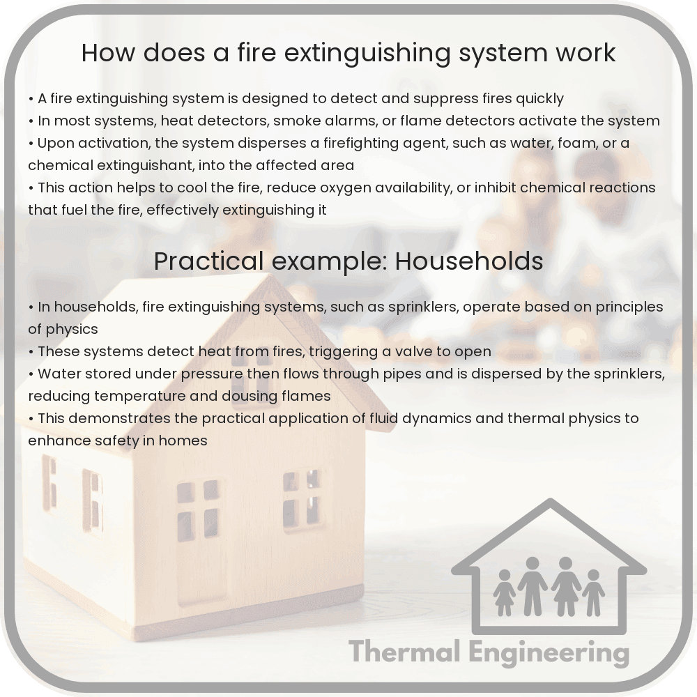
How does a fire extinguishing system work

Learn about fire extinguishing systems, their types, components, and how they operate to suppress fires effectively and ensure safety.

How does a fire extinguishing system work

Understanding Fire Extinguishing Systems

Fire extinguishing systems are critical components of building safety, designed to detect fires, suppress flames, and limit the spread of fire and smoke. These systems range from basic handheld extinguishers to sophisticated automatic setups. Learning how these systems work helps in understanding the various methods through which they help in combating fires.

Types of Fire Extinguishing Systems

There are several types of fire extinguishing systems, each suitable for different situations and types of fires, classified as Class A, B, C, D, and K. Here’s a brief look at the most common systems:

  • Water-based Systems: These include sprinklers which are generally used for Class A fires. They work by spraying water to cool the fire and reduce its oxygen supply.
  • Foam Systems: Effective for Class B fires (flammable liquids), foam extinguishing systems smother the fire by forming a barrier between the fuel and the air.
  • Dry Chemical Systems: Often used for Class B and C fires (flammable gases and electrical), these systems use compounds such as sodium bicarbonate to interrupt the chemical reaction that sustains a fire.
  • Carbon Dioxide Systems: Suitable for Class C fires, these systems displace oxygen and cool the fuel, effectively suffocating the fire.
  • Clean Agent Systems: These use halocarbon compounds or inert gases to suppress a fire without damaging sensitive equipment, making them ideal for data centers or areas with electronic devices.

Components of Fire Extinguishing Systems

A typical automated fire extinguishing system consists of the following components:

  1. Detection Devices: Smoke, heat, and flame detectors that sense fire signs and trigger the system.
  2. Alarm Systems: To alert occupants and possibly connected to remote monitoring stations.
  3. Control Panel: The brain of the system, deciding when to activate the suppression system.
  4. Suppression Means: The actual agents used (water, foam, dry chemical, etc.) to extinguish the fire.
  5. Delivery System: Comprising pipes, nozzles or hoses, which guide the suppressing agent to the fire.

How It Works

When a fire ignites, the first step in a modern fire extinguishing system is the detection of fire via smoke, heat, or flame detectors. Once a fire has been detected, the control panel evaluates the sensor information and activates the appropriate alarms. Then it initiates the discharge of the extinguishing agent. Depending on the system, water, foam, or specialized chemicals are released through sprinklers or nozzles, effectively targeting the combustion’s fuel, oxygen, or chemical reactions to suppress the fire.

For example, in an automatic sprinkler system, the sprinklers are connected via pipes to a water source. Each sprinkler head is closed off by a heat-sensitive element, typically a glass bulb filled with glycerin. When the temperature rises due to a fire, the glycerin expands and breaks the glass bulb, opening the valve and allowing water to flow from the exposed sprinkler head.

The Importance of Proper Maintenance and Use

Regular maintenance is crucial to ensure the effectiveness of any fire extinguishing system. This includes inspections, testing, and replacement of components like sensors and extinguishing agents. Properly maintained systems are vital in providing timely and effective suppression of fires, minimizing damage and protecting lives.

Understanding how fire extinguishing systems operate is key to appreciating their role in daily safety and the measures necessary to maintain such systems. Their proper use and regular maintenance can decidedly make the difference in emergency situations, potentially saving lives and properties.

Thermal control coatings for aerospace

Learn about thermal control coatings used in aerospace engineering to protect spacecraft from extreme temperatures in space.

Thermal control coatings for aerospace

Understanding Thermal Control Coatings in Aerospace Engineering

Thermal control coatings are specialized materials applied to the exterior of spacecraft to protect them from the extreme temperatures of space, which can vary drastically from intensely hot to extremely cold. These coatings are critical for maintaining the structural integrity of the spacecraft and the functionality of onboard instruments.

How Thermal Control Coatings Work

Thermal control coatings are designed to manage the heat load on a spacecraft caused by both the solar radiation and the cold of deep space. These coatings operate primarily through two mechanisms: thermal emission and solar reflectance.

  • Thermal Emission: This is the ability of the coating to emit infrared radiation, which helps in radiating heat away from the spacecraft.
  • Solar Reflectance: This refers to the coating’s ability to reflect solar radiation, preventing it from absorbing too much solar energy, which could increase its internal temperature.

Types of Thermal Control Coatings

There are several types of thermal control coatings used in aerospace engineering, each with its specific properties and applications:

  1. White Paints: These are pigmented coatings that offer good solar reflectance and are used widely on areas of spacecraft that are exposed directly to sunlight.
  2. Black Paints: Beneficial for their high emittance properties, black paints are utilized on parts of the spacecraft that require efficient heat dissipation.
  3. Metal Coatings: Metallic coatings, such as aluminum or silver, are applied to spacecraft surfaces for high reflectivity and emissivity. These are particularly useful in managing thermal loads between different parts of the spacecraft.
  4. Multi-layer Insulation (MLI): This insulation involves multiple thin layers of reflective films that prevent radiative heat transfer, effectively controlling the thermal environment within the spacecraft.

Performance Considerations

The effectiveness of thermal control coatings depends on various factors, including environmental exposure, thermal cycling, and material degradation over time. The properties of these coatings, such as absorptivity (α) and emissivity (ε), play a key role. The ideal thermal control coating has low absorptivity and high emissivity (α near 0 and ε near 1) to minimize heat absorption and maximize heat radiation.

Impact and Applications

Thermal control coatings are not only used in spacecraft but also play a crucial role in satellite technology, ensuring that instruments operate within their designated temperature ranges. These coatings contribute significantly to the longevity and success of missions by protecting sensitive equipment from thermal damage.

In the ongoing journey of space exploration, the development of advanced thermal control coatings continues to evolve, bringing forth materials with greater resilience to the harsh environment of space and more effective management of thermal extremes. The innovative combination of materials science and aerospace engineering leads to improvements in space mission safety and efficiency.

Conclusion

The application of thermal control coatings represents a critical intersection of physics and engineering, where understanding the heat dynamics in the vacuum of space directly informs the design and application of these materials. As space missions aim farther and involve more complex instrumentation, the role of thermal control coatings will only grow in importance, encapsulating a key aspect of aerospace engineering dedicated to overcoming the environmental challenges of space.

How does a thermal switch regulate temperature

Learn how a thermal switch, often called a thermostat, controls temperatures in devices from ovens to industrial machinery.

How does a thermal switch regulate temperature

Understanding the Function of a Thermal Switch in Temperature Regulation

A thermal switch, commonly known as a thermostat, plays a critical role in maintaining the desired temperature in various devices and systems, from household appliances like ovens and boilers to industrial equipment. Essentially, it is an automatic switch that controls the power flow to a device based on its temperature. Let us explore how this small but vital component works to ensure temperature regulation.

Basics of a Thermal Switch

A thermal switch operates on the principle of thermal expansion, which refers to the tendency of materials to change in volume in response to a change in temperature. This switch is typically made up of two primary components:

  • Bimetallic Strip: This is composed of two metals with different thermal expansion coefficients firmly bonded together. As the temperature changes, the differential expansion of these metals causes the strip to bend or deform.
  • Electrical Contacts: These are connected to the circuit and open or close as the bimetallic strip deforms, thereby controlling the current flow in the circuit.

How a Thermal Switch Regulates Temperature

The operation of a thermal switch is a straightforward process:

  1. As the temperature of the environment (or the device it is monitoring) increases, the bimetallic strip inside the switch heats up.
  2. The differing expansion rates of the metals in the bimetallic strip cause it to bend.
  3. Once the strip bends enough, it reaches a critical point where it either makes contact or breaks contact with another electrical contact point. This opens or closes the electrical circuit.
  4. This action either starts or stops the flow of electricity to the heating element or cooling mechanism, thereby regulating the temperature.
  5. As the temperature returns to the desired level, the bimetallic strip cools, returns to its original shape, and resets the contact points, restoring power if it was off, or shutting it off if it was on.

In practical applications, thermal switches can be used not only for turning a device or system on and off but also for activating alarms or other devices when a specified temperature limit is exceeded.

Applications of Thermal Switches

Thermal switches are utilized in a wide variety of applications, showcasing their versatility and importance in temperature-sensitive systems:

  • Household Appliances: Ovens, refrigerators, water heaters, and HVAC systems all use thermal switches to maintain safe and efficient operational temperatures.
  • Automotive: In vehicles, thermal switches regulate the temperature of engines and transmissions, preventing overheating.
  • Electronics: Thermal switches protect components like CPUs and power supplies from overheating by regulating internal temperatures.
  • Industrial Equipment: Large machinery and manufacturing processes rely on thermal switches to ensure that equipment operates within safe temperature ranges, thus preventing failures and extending equipment life.

Understanding the basic function and applications of thermal switches underscores their role in modern technology and everyday devices. By leveraging the physical property of thermal expansion, these switches provide a simple, reliable, and cost-effective solution for temperature regulation.

Conclusion

The thermal switch is a standout example of how basic physical principles, like thermal expansion, can be applied to solve practical engineering problems. Valve, in fields ranging from domestic appliances to complex industrial systems, ensuring that thermal switches not only improve performance and safety but also enhance energy efficiency and system reliability.

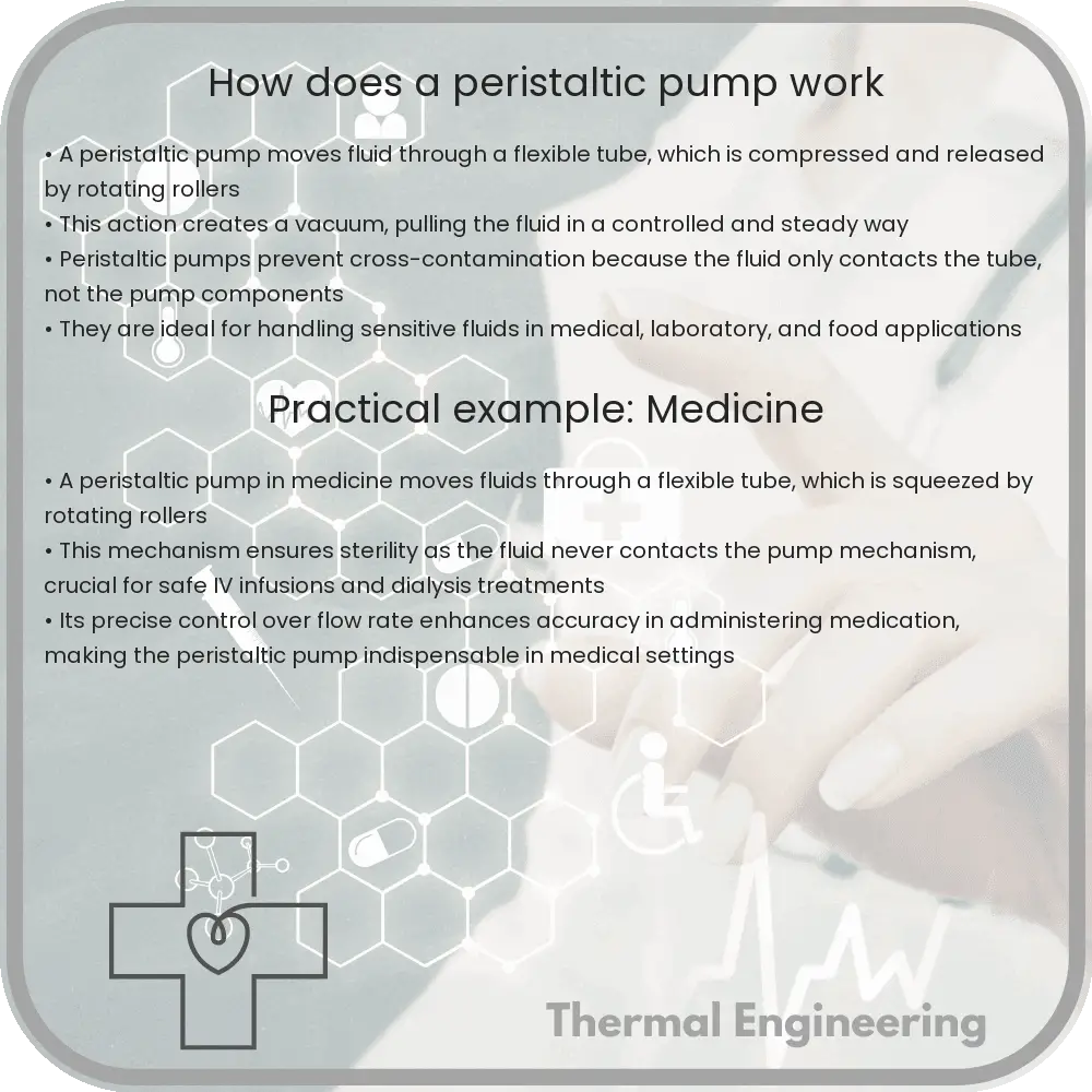
How does a peristaltic pump work

Learn about peristaltic pumps, their components, operating principles, advantages, and limitations in various industries.

How does a peristaltic pump work

Understanding the Peristaltic Pump

Peristaltic pumps are a type of positive displacement pump used to move fluids through a flexible tube, which is squeezed by a set of rollers or shoes. This design ensures that the fluid only contacts the tubing, not the moving parts of the pump, making it ideal for sterile processes and aggressive fluids. In this article, we’ll explore how peristaltic pumps work and their common applications.

Core Components of a Peristaltic Pump

  • Housing: Encloses all mechanical components and supports the motor and rollers/shoes.
  • Tubing: Flexible tube that carries the fluid. The material of the tube must be chosen carefully to ensure compatibility with the fluid and resilience against the pressure.
  • Rollers or Shoes: These components compress and massage the tube, propelling the fluid forward.
  • Motor: Drives the rollers or shoes to rotate, squeezing the tubing rhythmically.

How It Works

The operation of a peristaltic pump is based on alternating compression and relaxation of the tubing. Here’s a step-by-step breakdown:

  1. The motor rotates the rollers or shoes. As these elements make contact with the tubing, they compress it, closing it tightly.
  2. As the rollers or shoes move along the tube, the closed part of the tube moves as well; this pushes the fluid contained within that segment forward.
  3. Once the roller passes, the tube’s elasticity allows it to return to its original shape, creating a vacuum that draws more fluid into the tube from behind.
  4. This cycle repeats continuously, resulting in a steady and controllable flow of fluid through the tube.

The design ensures that the fluid does not come into contact with any pump mechanism other than the tubing, significantly reducing contamination risks. This characteristic, along with the ability to easily change the tubing and thus prevent cross-contamination, makes peristaltic pumps particularly useful in medical, pharmaceutical, and food industries.

Advantages and Limitations

Advantages

  • Sterility: As the fluid only contacts the tubing, the process is sterile.
  • Low maintenance: Without seals, valves, or glands, the pump is easier to maintain.
  • Gentle pumping action: Ideal for sensitive fluids like cultures or live cells.

Limitations

  • Tubing wear: Over time, the tubing might wear out and need replacement due to the constant squeezing and release.
  • Lower efficiency: The squeezing action is less energy-efficient compared to other pump types.
  • Limited pressure capabilities: Typically not suitable for extremely high-pressure applications.

Conclusion

Peristaltic pumps are uniquely suited for specific applications where contamination risk needs to be minimized and fluid integrity maintained. Understanding their operational mechanism helps in effectively integrating them into systems requiring high standards of hygiene and precision. Their straightforward, yet effective design continues to make them indispensable tools in various industries.

How does a membrane filter purify water

Learn how membrane filtration, a crucial water purification technology, uses various pore-sized barriers to remove contaminants effectively.

How does a membrane filter purify water

Understanding How a Membrane Filter Purifies Water

One of the essential technologies in water purification today involves the use of membrane filters. These filters operate at the microscopic level to remove contaminants from water, making it safe for drinking and other uses. This article explains the fundamental principles behind membrane filtration, how it is implemented, and why it is effective.

What is Membrane Filtration?

Membrane filtration is a physical separation process in which a contaminated fluid is passed through a barrier (the membrane) with very small pores. These pores allow molecules of water to pass through while blocking larger particles, pathogens, and other contaminants.

Types of Membrane Filtration

There are several types of membranes used in water purification, categorized based on their pore size:

  • Microfiltration (MF): Removes particles in the range of about 0.1 to 10 microns, including large bacteria and sediments.
  • Ultrafiltration (UF): Targets particles from about 0.01 to 0.1 microns, including viruses, some bacteria, and large molecular weight solutes.
  • Nanofiltration (NF): Effective for removing particles sized 0.001 to 0.01 microns, capable of excluding most organic compounds and some salts.
  • Reverse Osmosis (RO): Has the smallest pore size and can remove particles as small as 0.0001 microns, filtering out almost all particles, including salts and monovalent ions.

How Does Membrane Filtration Work in Water Purification?

The process of water purification using a membrane filter involves several steps:

  1. Intake: Water from a source is taken in for processing. This could be brackish, grey, or wastewater depending upon the application.
  2. Pre-treatment: Water undergoes initial processing to remove large sediments and particles. This helps prevent clogging or damage to the main filtration membranes.
  3. Filtration: Water is then pushed through the membrane material. Depending on the membrane used (MF, UF, NF, RO), different contaminants are removed based on their size relative to the membrane’s pore size.
  4. Post-treatment: The purified water is sometimes treated chemically or with ultraviolet light to ensure sterilization, and the concentrate (contaminants and particles that did not pass through) is disposed of or treated further.

Pressure is a key factor in this process. Higher pressure is required to push water through smaller pores, which is why RO systems require more energy compared to MF or UF systems.

Advantages of Membrane Filtration

Membrane filtration offers several advantages over traditional water purification methods:

  • Effectiveness: Capable of removing a wide range of contaminants including pathogens, chemicals, and sediments effectively.
  • Energy Efficiency: Modern membrane systems, especially ultrafiltration, use less energy than methods relying on heat or extensive chemical treatments.
  • Scalability: Systems can be designed for various scales, from portable devices for personal use to large-scale plants for municipal water treatment.
  • Environmentally Friendly: Produces less chemical and secondary waste compared to conventional methods.

In conclusion, membrane filtration is a powerful tool for purifying water, ensuring safety and compliance with health standards. As technology advances, these systems continue to improve in both efficiency and cost-effectiveness, making purified water more accessible around the world.

How does a scroll compressor compress air

Learn how scroll compressors efficiently compress air in HVAC and refrigeration systems through unique design and continuous motion.

How does a scroll compressor compress air

Understanding How a Scroll Compressor Compresses Air

Scroll compressors, widely used in air conditioning and refrigeration systems, stand out due to their unique design and efficient performance. But how exactly do they compress air? This article breaks down the operational principles of scroll compressors, explaining their mechanism in a simplified manner suitable for all readers interested in engineering concepts.

Principles of Scroll Compression

A scroll compressor consists of two spiral-shaped scrolls. One scroll remains stationary, while the other orbits around it. This movement creates pockets of compressed air. The key to understanding scroll compressors lies in these two primary components:

  • Fixed Scroll: This scroll stays in place and is anchored securely to the compressor’s body.
  • Orbiting Scroll: This scroll moves in a tight circular motion without rotating, maintaining the same orientation throughout its motion.

The Compression Cycle

The process of air compression in a scroll compressor can be broken down into several distinct phases:

  1. Suction Phase: Air is drawn into the compressor through an intake valve, filling the spaces between the scrolls.
  2. Compression Phase: As the orbiting scroll moves, the pockets of air trapped between the scrolls are progressively pushed into smaller areas, effectively increasing the air pressure.
  3. Discharge Phase: Compressed air is pushed towards the center of the scrolls and eventually discharged through an outlet valve at a considerably higher pressure.

The efficiency of a scroll compressor is largely due to the continuous and gradual movement of the orbiting scroll, which minimizes pulses in the flow and reduces energy loss typically observed in other types of compressors.

Advantages of Scroll Compressors

Scroll compressors offer several advantages making them popular in various applications:

  • Quiet Operation: The smooth, continuous motion of the orbiting scroll doesn’t produce much noise compared to other compressor types, which often involve more mechanical impacts and vibrations.
  • Reliability: Fewer moving parts mean less wear and tear, thus increasing reliability and lifespan.
  • Energy Efficiency: The tight seal between the scrolls and the continuous compression cycle improve energy efficiency by minimizing air leakage and reducing the cyclical load on the motor.

Applications in Real-World Engineering

Due to their efficiency and reliability, scroll compressors are extensively used in HVAC (Heating, Ventilation, and Air Conditioning) systems, refrigeration, and even in some automotive applications. These compressors are particularly favored in situations where noise reduction and space savings are critical.

In conclusion, the elegant design of scroll compressors demonstrates a fascinating application of basic physics principles in a sophisticated mechanical device. By understanding how these devices work, individuals can appreciate the clever engineering used to maintain our comfort and advance technology in multiple fields.

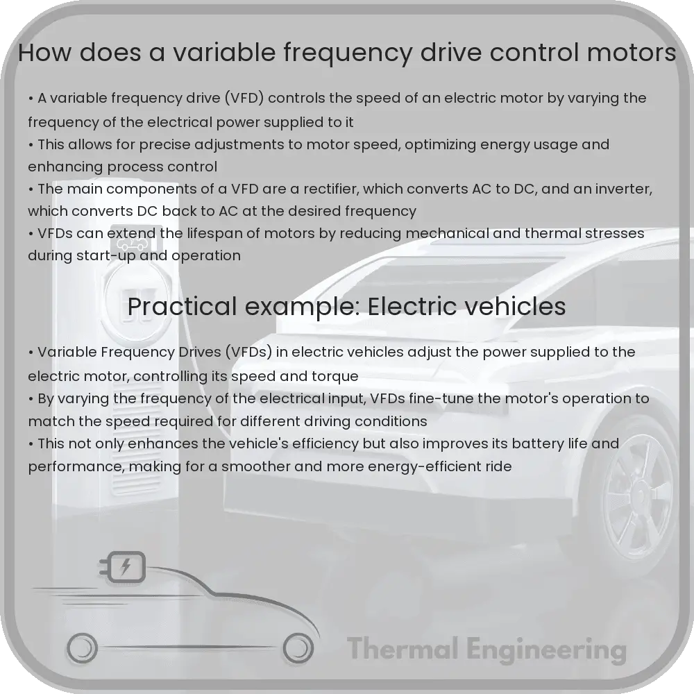
How does a variable frequency drive control motors

Learn what Variable Frequency Drives (VFDs) are, including their key components, operation principles, and benefits in controlling motor speeds.

How does a variable frequency drive control motors

Understanding Variable Frequency Drives

A Variable Frequency Drive (VFD) is a type of motor controller that drives an electric motor by varying the frequency and voltage supplied to the electric motor. Other names for a VFD are variable speed drive, adjustable speed drive, adjustable frequency drive, AC drive, microdrive, and inverter. The application of VFDs is an essential part of electrical engineering that deals with the control and automation of electric motors.

Basic Principle

The basic principle behind a VFD operation is quite simple. VFDs convert the input electrical power from mains AC (alternating current) to DC (direct current) and then back to a variable AC frequency. This variable frequency AC output allows precise control of the speed of a motor, which can lead to significant energy savings and control benefits.

Key Components

  • Rectifier: The rectifier converts AC power from the mains to DC. The type of rectifier used in VFDs can vary, impacting the quality and efficiency of the DC output.
  • Inverter: The inverter converts the DC power back into AC. However, it allows for the adjustment of the frequency and voltage of the output, which controls the speed and torque of the motor.
  • Filter: Most VFDs include a filter to smooth out the DC power before it is re-converted to AC, ensuring a more stable and consistent output.
  • Control Unit: The control unit governs the operation of the rectifier, inverter, and other components based on inputs from the user or an automated system. It adjusts the frequency and voltage according to the desired motor performance.

How a VFD Controls Motor Speed

The VFD’s ability to control motor speed is chiefly due to its capacity to vary the frequency of the AC signal supplied to the motor. The speed of an AC motor is primarily dictated by the following equation where f is the frequency of the AC power supplied to the motor, and P is the number of poles the motor has:

Speed = (120 * f) / P

By adjusting the frequency f, the VFD controls the speed of the AC motor. This is crucial for applications requiring different speeds during operation or for conserving energy when full speed isn’t necessary.

Benefits of Using Variable Frequency Drives

  • Energy Efficiency: By running motors only at needed speeds, significant energy savings can be achieved, especially in applications involving variable load conditions.
  • Extended Motor Life: VFDs can reduce the mechanical and thermal stress on motors by controlling the acceleration and deceleration cycles more smoothly.
  • Improved Process Control: Precise speed control allows for better process control in industrial settings, leading to improved product quality and less waste.
  • Decreased Operational Costs: Besides saving on energy, VFDs can lower maintenance costs by reducing wear and tear on equipment.

Conclusion

Variable Frequency Drives are a pivotal component in modern industrial automation, offering not only significant cost and energy savings but also enhancing the detailed control over motor operations. Their role in improving the efficiency of electric motors makes them an indispensable tool in the field of electrical engineering.