Facebook Instagram Youtube Twitter

Coalescer | Liquid Separation, Oil/Water Treatment

Learn about coalescers, key devices for separating immiscible liquids like oil and water, essential in industries such as petroleum refining and wastewater treatment.

Coalescer | Liquid Separation, Oil/Water Treatment

Understanding Coalescers in Liquid Separation and Oil/Water Treatment

Coalescers are crucial engineering tools used in various industries to separate immiscible liquids, most commonly oil and water. These devices play a pivotal role in water treatment processes, petroleum refining, and chemical industries. They provide a cost-effective and efficient method for separating fluids based on differences in their densities. This article delves into the principles of coalescers, their types, and their applications in industry.

Principle of Operation

Coalescers work by gathering small droplets of one liquid suspended in another and merging them into larger droplets. Larger droplets have a faster settling or rising velocity than smaller droplets according to Stokes’ law. The law is given by the equation:

\[ v = \frac{2gr^2(\rho_1-\rho_2)}{9\mu} \]

where:

  • v is the terminal velocity,
  • g is the acceleration due to gravity,
  • r is the radius of the droplet,
  • \(\rho_1\) and \(\rho_2\) are the densities of the two liquids, respectively,
  • \(\mu\) is the viscosity of the continuous phase.

By increasing droplet size, the separation process becomes more efficient and faster. The design of coalescers usually focuses on maximizing the collision rate of small droplets to facilitate their coalescence into larger ones.

Types of Coalescers

There are two primary types of coalescers used in industry:

  1. Mechanical Coalescers: These utilize physical media such as baffles or fiber mats to filter and merge droplets. The media causes small droplets to collide and fuse together as they move through the filter.
  2. Electrostatic Coalescers: By applying a high-voltage electrical field, these coalescers induce charges on the droplets, causing them to attract each other and merge into bigger drops. They are particularly effective for emulsions that are difficult to separate mechanically.

Applications in Industry

Coalescers are extensively used in various industrial sectors:

  • Petroleum Industry: They are employed for separating water from crude oil. This is crucial for downstream processing and ensuring the quality of refined products.
  • Chemical Processing: In chemical manufacturing, coalescers are used to separate products and by-products that are immiscible, enhancing product purity and process efficiency.
  • Environmental Engineering: Coalescers play a role in industrial wastewater treatment by separating oily water emulsions before treatment, thereby reducing pollutant load and improving water quality.
  • Food and Beverage Industry: They assist in clarifying products by removing oils and other impurities, ensuring product consistency and quality.

For optimal performance, the design and selection of a coalescer must consider factors such as the types of liquids to be separated, their volume throughput, the size of the dispersed droplets, and the required degree of separation.

Conclusion

Coalescers are vital components in sectors where liquid separation is a frequent and necessary task. They significantly improve the efficiency of separation processes, enhance product quality, and contribute to environmental protection. As industries continue to focus on sustainability and efficiency, understanding and optimizing coalescers will remain an essential area of research and engineering.
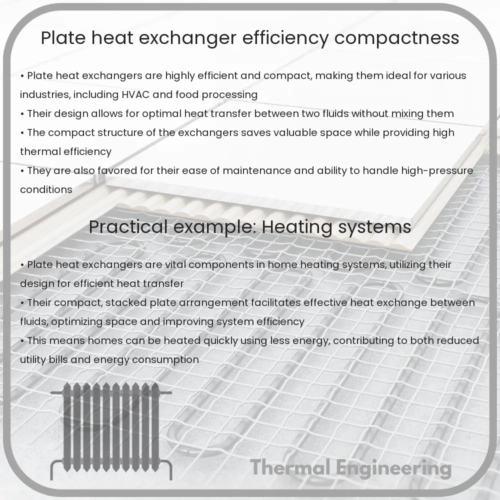
Plate Heat Exchanger | Efficiency, Compactness

Learn about plate heat exchangers, their efficient design, and widespread industrial applications for optimized thermal management.

Plate Heat Exchanger | Efficiency, Compactness

Understanding Plate Heat Exchangers: Efficiency and Compactness

Plate heat exchangers are a type of heat exchanger design that uses corrugated plates to channel two liquids for the purpose of heat transfer. This design is favored for its high efficiency and compact nature, making it an ideal choice in industries where space and energy efficiency are paramount. In this article, we will explore the principles behind plate heat exchangers, their design features, and the advantages they provide in thermal management.

Basic Configuration of Plate Heat Exchangers

A plate heat exchanger consists of multiple thin, slightly separated plates that have very large surface areas and fluid flow passages for heat transfer. This stacked-plate arrangement can be more effective than conventional heat exchangers, such as shell and tube types, due to the increased surface area and the closer proximity of the fluids. Each heat exchanger plate is fitted with a gasket, which seals the interplate channel and directs the fluids into alternate channels. The plates are pressed with chevron or other patterns, which promote turbulent flow and support the plates against differential pressure.

Efficiency of Plate Heat Exchangers

The efficiency of heat exchangers is often defined by the ability to transfer heat while maintaining a compact footprint. Plate heat exchangers excel in this area due to several key features:

  • High Surface Area: The large surface area of the plates facilitates a high rate of heat transfer compared to other heat exchanger types.
  • Turbulent Flow: The corrugation patterns on the plates induce turbulent flow. This turbulence effectively disrupts the boundary layer that forms when a fluid flows across a surface, enhancing the heat transfer coefficient.
  • Counter-Current Flow: Most plate heat exchangers operate under a counter-current flow arrangement which maximizes the temperature gradient between the hot and cold fluids throughout the heat exchanger.

Compactness of Plate Heat Exchangers

One of the distinguishing features of plate heat exchangers is their compact design. The factors contributing to this compactness include:

  • Thinner Plates: The use of thinner plates not only reduces the volume and weight of the heat exchanger but also decreases the heat path, which improves the heat transfer efficiency.
  • Stackable Design: The ability to stack plates closely together reduces the space needed for the heat exchanger installation.

Applications of Plate Heat Exchangers

Due to their high efficiency and compact size, plate heat exchangers are widely used in various industries, including:

  • Food and Beverage Processing: Pasteurization, cooling, and heating processes.
  • Pharmaceuticals: Heating, cooling, and control of precise temperature conditions.
  • Power Plants: Waste heat recovery and cooling systems.
  • Marine Applications: Heat recovery and engine cooling.

In conclusion, plate heat exchangers offer superior performance in terms of efficiency and space utilization. Their ability to handle a wide range of temperatures and pressures, coupled with their robust design, makes them a versatile solution in many thermal management scenarios. Whether for heating or cooling, the plate heat exchanger represents a sophisticated, efficient approach to temperature regulation in industrial processes.

Condenser | Heat Rejection, Vapor Condensation

Learn about condensers, their roles in heat rejection and vapor condensation, and how they enhance efficiency in thermal systems.

Condenser | Heat Rejection, Vapor Condensation

Understanding the Condenser: Heat Rejection and Vapor Condensation

A condenser is a critical component in various engineering systems, notably in refrigeration, air conditioning, and power generation. It plays a pivotal role in the thermodynamic cycle of these systems, facilitating the transition of a substance from its gaseous to its liquid state. This article explores the fundamental principles behind condensers, focusing on their function in heat rejection and vapor condensation.

How Condensers Work

In simplest terms, a condenser is a heat exchanger device that cools vapor into liquid. This process involves removing heat from the vapor and discharging it into the surrounding environment.

Types of Condensers

There are primarily three types of condensers used in engineering applications:

  • Air-cooled condensers: These condensers use air as the cooling medium, which is blown across the exterior of heat transfer coils containing the hot vapor.
  • Water-cooled condensers: These use water as the cooling medium. Water is circulated through a set of coils that condense the vapor inside by removing heat from it.
  • Evaporative condensers: Combining the principles of water and air cooling, these condensers use the evaporation of water to remove additional heat and facilitate more efficient condensation.

Heat Rejection Process

Heat rejection in a condenser marks the end of the upper part of a thermodynamic cycle. It is critical to the efficiency of the cycle, whether it be in a power plant, refrigerator, or air conditioning system. The general process can be described as follows:

  • The vapor enters the condenser at a high temperature and pressure.
  • Cooling medium (air or water) absorbs the heat from the vapor.
  • The reduction in vapor temperature leads to condensation, turning it back into liquid form at high pressure.
  • The latent heat, released during condensation, is carried away by the cooling medium.

Role of Condensation in Engineering Systems

The condensation process within a condenser is crucial for several reasons:

  • Enhances System Efficiency: By effectively removing heat, condensers help in maintaining the efficiency of the thermodynamic cycle.
  • Environmental Heat Management: Condensers manage the heat output of systems, crucial in applications where overheating could be detrimental.
  • Fluid Recovery: In chemical plants and natural gas processing, condensers help in recovering fluids that can be reused in the process or further processed.

Mathematical Description of Condensing Process

In engineering calculations, the performance of a condenser can often be analyzed using the principle of heat transfer. The basic equation used is:

Q = m * hfg

Where:

  • Q is the amount of heat rejected (in watts or joules),
  • m is the mass flow rate of the vapor (in kg/s), and
  • hfg is the latent heat of vaporization (in joules per kg), characteristic of the fluid being condensed.

This formula helps in determining the heat transfer rate which is essential for sizing the condenser and ensuring it operates efficiently under the desired conditions.

Conclusion

Condensers are indispensable components in many thermal systems, ensuring the effective removal of heat and facilitating the phase change necessary for cycles to continue operating efficiently. Understanding the basic functions and types of condensers, along with their role in heat rejection and vapor condensation, is fundamental for anyone involved in their selection, design, or maintenance.

As we continue to rely on such thermal systems for a variety of industrial and commercial applications, the optimization of condenser technology remains a crucial aspect of engineering research and development.

Liquid Ring Vacuum Pump | Chemical Processing, Vacuum

Learn how liquid ring vacuum pumps function and their critical role in chemical processing, including operation, applications, and maintenance tips.

Liquid Ring Vacuum Pump | Chemical Processing, Vacuum

Understanding Liquid Ring Vacuum Pumps in Chemical Processing

Liquid ring vacuum pumps are a pivotal piece of equipment in various industries, playing a crucial role especially in chemical processing where they manage substances in vacuum conditions. Their unique design and operation allow them to handle wet loads and to be fairly tolerant of contaminants that might be encountered during chemical processes. Here, we delve into the fundamentals and operational principles of liquid ring vacuum pumps.

Operating Principle

A liquid ring vacuum pump consists of an impeller with blades that rotate within a cylindrical casing partially filled with sealing fluid, often water. As the impeller rotates, centrifugal force causes the liquid to form a ring against the casing due to gravitational pull, creating a series of crescent-shaped chambers between the blades of the impeller. As the liquid ring rotates, the volume of these chambers changes, leading to the creation of a vacuum.

The operational process can be divided into four key steps:

  1. Expansion: As the impeller blade moves from the top of the cylinder to the middle, it expands the space in front of it, reducing pressure and creating suction that draws in gases or vapors from the process.
  2. Compression: As the blade passes the inlet port and moves downward, the crescent space begins to decrease, increasing the pressure and compressing the gas within.
  3. Sealant injection: During operation, fresh sealing liquid is continuously fed into the pump, maintaining the ring’s integrity and assisting in the gas compression process.
  4. Discharge: As the trapped gas is compressed, it reaches the discharge port where it is pushed out of the pump.

Applications in Chemical Processing

Liquid ring vacuum pumps are favored in chemical processing due to their ability to handle explosive gases and vapors with a reduced risk of ignition. The process involves potentially dangerous and volatile substances, where any spark could lead to significant hazards.

  • Volatility and contamination: The water or other sealant in the pump can absorb some of the vapors from volatile substances, reducing the risk of damage or contamination.
  • Efficiency in handling wet or dry loads: Whether dealing with wet or dry gases, liquid ring vacuum pumps can perform effectively, making them versatile for various phases of chemical processing.
  • Minimizing chemical exposure: The sealant liquid can also act as a barrier limiting the exposure of the pump’s mechanical parts to harsh chemicals, thereby extending the lifespan of the equipment.

Maintenance and Efficiency

Maintaining a liquid ring vacuum pump involves regular checks and replacement of the sealing liquid. The efficiency of the pump can deteriorate if the sealant is contaminated or if the sealant level is not maintained, leading to decreased vacuum performance.

Moreover, operators need to select the right sealant based on the processing environment — water is commonly used, but for processes involving solvents or where water may react with the process gases, oils or other chemical fluids might be preferred.

Conclusion

Liquid ring vacuum pumps serve as an essential component in chemical processing, ensuring safe handling and efficient management of gases and vapors within vacuum systems. By understanding the basic principles, appropriate applications, and maintenance needs, operators can optimize the use of these pumps in their industrial applications.

Air Separator | Efficiency, Heating/Cooling Systems

Learn how air separators enhance the efficiency of heating and cooling systems by removing air and gas, reducing noise, and preventing corrosion.

Air Separator | Efficiency, Heating/Cooling Systems

Understanding Air Separators in Heating and Cooling Systems

Air separators are crucial components in heating and cooling systems, particularly in hydronic systems that use water to heat and cool a space. Their main role is to remove air and gas from the water circuit which, if left unchecked, can lead to inefficiencies, noise, and potentially damaging conditions like corrosion and pump cavitation. In this article, we will explore how air separators work, their efficiency, and their impact on system performance.

How Air Separators Work

Air separators are installed in the piping of heating and cooling systems and operate on the principle of air release. The mechanism typically involves the slowing of water velocity coupled with direction changes, which facilitates the release of air bubbles trapped in the water. The freed air collects at the top of the separator and is then vented out automatically or manually.

Types of Air Separators

  • Tangential/Vortex Air Separators: They create a vortex that helps separate the air from the water due to centrifugal forces.
  • Spiral Air Separators: Use a helical shaped pathway to slow down the fluid, allowing air bubbles to ascend and separate from the fluid stream.
  • Coalescing Air & Dirt Separators: These enhance the function by not only removing air but also trapping dirt particles, which can also degrade system performance.

Efficiency of Air Separators

The efficiency of an air separator is determined by its ability to remove dissolved and free air from the system. Essential factors affecting efficiency include separator design, flow velocity through the separator, and the condition of the system fluid. Advanced models like coalescing types or those with microbubble technology can remove almost 100% of the entrained air and microbubbles, thereby enhancing the overall operational efficiency of the system.

Efficient air removal helps in:

  • Reducing energy consumption by ensuring that heat transfer surfaces remain effective.
  • Minimizing maintenance costs by preventing issues like corrosion and pump cavitation.
  • Improving system lifespan and reducing noise generated by trapped air within the system.

Role in Heating and Cooling Systems

In heating systems, air separators prevent air locks which can stop the circulation of hot water and thus impede the proper heating of spaces. In cooling systems, similar challenges involve hindering the transfer of cool temperatures. By ensuring that the system is free from air and gas pockets, air separators maintain the continuity and effectiveness of the system’s operation.

Conclusion

Air separators are vital for the efficient, quiet, and effective operation of heating and cooling systems. By choosing the right type of air separator and ensuring its proper maintenance, system operators can save energy, reduce operational costs, and extend the life of the system. Understanding the simple yet critical role of these components helps in optimizing the performance of HVAC systems and ensuring a comfortable indoor environment.

For those interested in more technical engineering concepts and their real-world applications, staying informed about basic components such as air separators in different systems can provide foundational knowledge that is useful in both academic and professional settings.

Flow Nozzle | Measurement, High Velocity Fluids

Learn about flow nozzles, essential tools for measuring high-velocity fluid flow rates in various industrial applications.

Flow Nozzle | Measurement, High Velocity Fluids

Understanding Flow Nozzles in High Velocity Fluid Measurement

A flow nozzle is a critical instrument used in engineering to measure the rate of flow of liquids and gases in conduits. This device is especially favored for handling high-velocity fluids due to its unique design characteristics that optimize performance under such conditions. In this article, we will explore how flow nozzles function, their advantages, and their typical applications.

How Flow Nozzles Work

Flow nozzles are based on the principle of fluid dynamics, specifically the Bernoulli Principle, which states that an increase in the speed of a fluid occurs simultaneously with a decrease in pressure or a decrease in the fluid’s potential energy. A flow nozzle features a converging section followed by a throat (the narrowest part of the nozzle). As the fluid enters the nozzle, it accelerates and its pressure decreases. Measuring the pressure differential before and after the nozzle allows for the calculation of the fluid’s velocity and subsequently, its flow rate.

Design and Geometry

The internal contouring of a flow nozzle is such that it provides a smooth transition from the pipe to the throat. This design minimizes the loss of energy due to friction and other factors, making the flow nozzle an efficient tool for flow measurement. The typical shape of a flow nozzle is characterized by:

  • A short, smooth inlet followed by a tapered converging section.
  • A relatively short throat to streamline the accelerated fluid.
  • An optional diverging section post-throat to help in the recovery of some pressure.

Advantages of Using Flow Nozzles

Some of the main benefits of using flow nozzles, especially in dealing with high-velocity fluids, include:

  • Durability: Flow nozzles are robust and withstand high temperatures and pressures, making them ideal for harsh industrial environments.
  • High Accuracy: Due to their design, flow nozzles provide accurate measurements, essential for optimal operation and safety.
  • Minimal Energy Loss: The streamlined design allows for minimal loss of energy, which is crucial in high-speed fluid applications.
  • Versatility: These devices can be used with a wide range of fluids, including steam, gas, and liquids.

Applications of Flow Nozzles

Flow nozzles are commonly used in industries where high-velocity flow measurement is critical, such as:

  • Power generation (e.g., steam flow measurement in power plants).
  • Chemical processing.
  • Petroleum and refineries.
  • Aerospace for testing and operations.

Calculating Flow Rate Using a Flow Nozzle

The flow rate through a flow nozzle can be calculated using the following simplified version of the Bernoulli Equation and Continuity Equation:

\[ \dot{Q} = C_d \times A_{throat} \times \sqrt{ \frac{2 \times \Delta P}{\rho} } \]

Where:

  • \(\dot{Q}\) is the flow rate.
  • \(C_d\) is the discharge coefficient, which is determined empirically and corrects for the flow being less than ideal.
  • \(A_{throat}\) is the cross-sectional area of the nozzle’s throat.
  • \(\Delta P\) is the pressure differential across the nozzle.
  • \(\rho\) is the density of the fluid.

This calculation assumes steady, incompressible flow, although corrections can be made to account for compressible flows, particularly gases, at high velocities.

In conclusion, the flow nozzle is a crucial tool in fluid dynamics, particularly suited to high-velocity and high-pressure measurement applications. With its robust design and high accuracy, it plays an indispensable role in many industrial processes, ensuring efficient operation and safety.

Reciprocating Compressor | High Pressure, Refrigeration

Learn about reciprocating compressors, essential for industries like refrigeration and petrochemicals, focusing on their design, operation, and applications.

Reciprocating Compressor | High Pressure, Refrigeration

Understanding Reciprocating Compressors in High Pressure and Refrigeration Applications

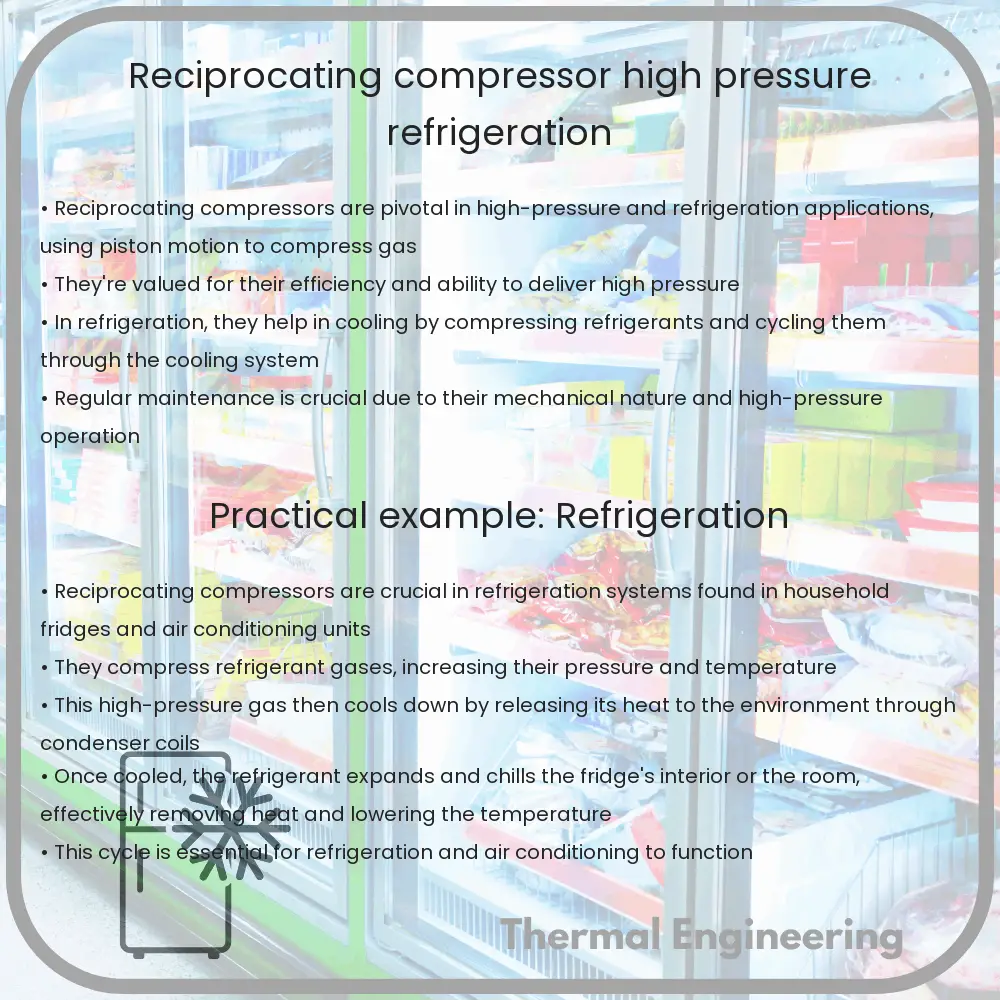
Reciprocating compressors are vital components in various industrial and refrigeration processes, playing a crucial role in controlling and maintaining desired pressure levels. Commonly found in industries such as oil and gas, refrigeration, and air conditioning, understanding how these machines work can provide a deeper insight into their essential function in modern engineering.

What is a Reciprocating Compressor?

A reciprocating compressor, also known as a piston compressor, is a mechanical device that increases the pressure of a gas by reducing its volume. This is accomplished through the reciprocating motion of a piston within a cylinder. As the piston moves downwards, it creates a vacuum, drawing the gas into the cylinder. As the piston moves upwards, the gas is compressed and then discharged into the output system at higher pressure.

Components of a Reciprocating Compressor

  • Cylinder: The chamber where gas compression takes place.
  • Piston: Moves reciprocally within the cylinder to compress the gas.
  • Crankshaft: Converts the rotational motion into reciprocating motion.
  • Valve: Manages the intake and discharge of gas in the cylinder.
  • Connecting Rod: Links the piston to the crankshaft.

Types of Reciprocating Compressors

Reciprocating compressors can be single-stage or multi-stage. A single-stage compressor completes the compression cycle in a single stroke of the piston, making it suitable for lower pressure requirements. The multi-stage compressor, by contrast, uses multiple pistons in a series, each dedicated to a stage of compression, allowing it to achieve much higher pressures ideal for heavy-duty applications.

Applications in High Pressure and Refrigeration

  1. Refrigeration: Reciprocating compressors are commonly used in refrigeration systems to compress refrigerants and maintain the required temperature in refrigerated spaces or appliances.
  2. Gas Transmission: High pressure reciprocating compressors are essential for the natural gas industry, where they are used to transport gas along pipelines over long distances.
  3. Petrochemical and Oil Refineries: These compressors compress raw natural gas and facilitate its purification and transportation.
  4. Auto Industry: Used in air brake systems for heavy-duty vehicles and compressing air in vehicle workshops.

Design Considerations for Efficiency and Reliability

Ensuring the efficiency and reliability of a reciprocating compressor involves several key considerations:

  • Pressure Requirements: The design must accommodate the maximum and minimum system pressures.
  • Gas Properties: Different gases have different thermodynamic properties that affect compressor design, such as corrosiveness or condensation risks.
  • Temperature Control: Effective cooling systems are necessary, especially in multi-stage compressors, to manage the heat generated during gas compression.
  • Vibration and Noise Reduction: Reciprocating compressors generate significant vibration and noise, and appropriate measures should be in place to mitigate these effects.
  • Maintenance Needs: Easy access to wear-prone components and robust design are critical for reducing maintenance costs and extending the lifespan of the equipment.

Conclusion

Reciprocating compressors are indispensable in both general-purpose applications in industries and specialized areas such as refrigeration and high-pressure systems. Their ability to effectively increase gas pressure by simple mechanical motion, coupled with the adaptability to different gas types and conditions, makes them a fundamental part of modern industrial operations. Understanding the operational mechanics, design considerations, and applications help in appreciating the critical role played by these devices in various sectors.

Hydraulic Turbine | Water to Mechanical Power, Renewable

Explore how hydraulic turbines convert water energy into mechanical power, their types, working principles, efficiency, and applications in renewable energy.

Hydraulic Turbine | Water to Mechanical Power, Renewable

Understanding Hydraulic Turbines: Converting Water to Mechanical Power

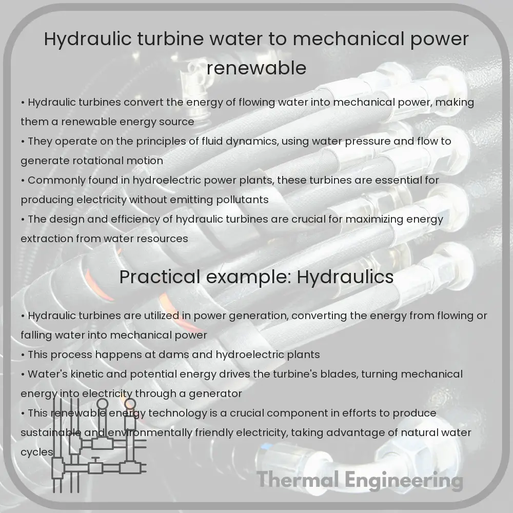
Hydraulic turbines are a cornerstone of renewable energy technology, primarily used for electricity generation in hydroelectric power stations. These turbines convert the energy from flowing or falling water into mechanical power, which is then transformed into electrical energy using generators. This process not only harnesses a renewable source of energy but also contributes to the reduction of carbon emissions by displacing fossil fuel-dependent power generation methods.

Types of Hydraulic Turbines

There are several types of hydraulic turbines, each designed to operate efficiently under specific conditions. The most common ones include:

  • Pelton Wheel – Best suited for high head and low flow situations. It features a wheel with spoon-shaped buckets that capture water from a high-velocity jet, causing the wheel to rotate.
  • Francis Turbine – This is a reaction turbine that operates well in medium head and flow conditions. It has a spiral casing that surrounds a series of fixed blades that guide the water smoothly onto a runner.
  • Kaplan Turbine – Designed for low head and high flow environments. This turbine includes adjustable blades and is highly efficient in locations where water flow varies.

Working Principle of Hydraulic Turbines

The basic principle behind all hydraulic turbines is the conversion of hydraulic energy (energy possessed by water) into mechanical energy (the rotation of a turbine’s rotor). This is achieved through two primary forces:

  • Impulse – In impulse turbines, like the Pelton wheel, the kinetic energy of water is converted into mechanical energy through jets that directly strike the turbine buckets.
  • Reaction – Reaction turbines, such as the Francis and Kaplan, use both the water’s pressure and kinetic energy to generate movement. The water enters the turbine under pressure, filling the turbine’s blades to create a continuous reaction that drives the blades and spins the rotor.

Energy Conversion and Efficiency

The efficiency of a hydraulic turbine depends on how well it converts the energy of water into mechanical energy. The formula to calculate the power output from a hydraulic turbine is expressed as:

P = ρ * g * Q * H * η

Where:

  • P is the power output in watts
  • ρ (rho) is the density of water (approximately 1000 kg/m3 for fresh water)
  • g is the acceleration due to gravity (9.81 m/s2)
  • Q is the flow rate in cubic meters per second (m3/s)
  • H is the head or the height of the water column in meters (m)
  • η (eta) is the efficiency factor, a unitless coefficient ranging from 0 to 1

The efficiency, indicated by η, varies depending on the type of turbine and the specific installation. Modern designs can achieve efficiencies as high as 90% or more under optimal conditions.

Applications and Future Potential

Hydraulic turbines are predominantly used in the generation of hydroelectric power. Nevertheless, their application is not limited to large-scale power generation. They are also used in smaller installations, like micro-hydro systems in rural or remote areas where grid connectivity is unreliable. As the technology progresses and the focus on renewable energy intensifies, hydraulic turbines play a crucial role in the global shift towards sustainable energy sources.

Seeing the continuous advancements in turbine technology and the growing emphasis on reducing carbon footprints, expect further improvements in turbine efficiency and adaptability. This will likely extend their use in even more diverse conditions and contribute more significantly to global renewable energy supply.

Fluid Coupling | Smooth Start-ups, Automotive Cooling

Learn how fluid coupling enhances smooth power transmission and cooling in automotive and industrial applications.

Fluid Coupling | Smooth Start-ups, Automotive Cooling

Understanding Fluid Coupling: Smooth Start-ups and Automotive Cooling

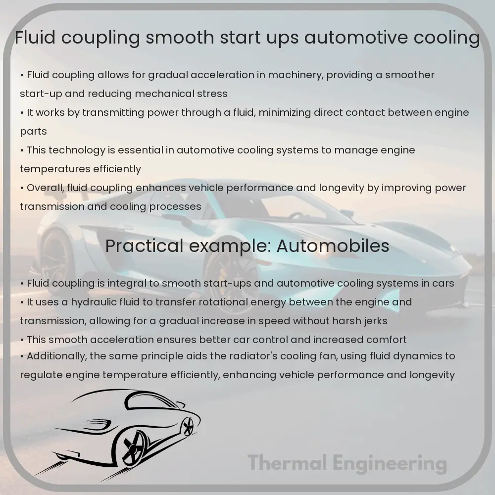
Fluid coupling is a fascinating component widely used in automotive and industrial applications to enable smooth transmission of rotational power. Essentially, it is a hydrodynamic device that uses a liquid medium to transmit torque between the shafts, providing a smooth, gradual acceleration and improving operational efficiency. Let’s break down how fluid couplings work and their role in various systems, particularly focusing on their use in smooth start-ups and automotive cooling systems.

How Fluid Coupling Works

A fluid coupling consists of three primary parts: the housing (also known as the shell), which is filled with fluid; an input shaft connected to an impeller (or pump); and an output shaft connected to a turbine. The impeller and the turbine sit facing each other with a slight gap and are enclosed inside the shell. The operation begins when the input shaft driven by an engine or motor causes the impeller to spin. As the impeller spins, it impels the fluid outward to the turbine blades, thereby transferring the torque to the output shaft.

The beauty of a fluid coupling is that it provides a variable torque depending on the speed. At low speeds, the fluid doesn’t transfer much torque, allowing for gentle and controlled acceleration. As the engine’s speed increases, the fluid is thrown outward with greater force, and more torque is transmitted to the output shaft, gradually ramping up to full speed and power.

Advantages of Using Fluid Couplings

  • Smooth Start-ups: Fluid couplings allow for a soft start capability, reducing the stress on mechanical components. This is crucial in heavy machinery and automotive applications where sudden starts could lead to premature wear or failure of components.
  • Load Balancing: They help distribute drive energy effectively when there are fluctuations in load, thereby safeguarding the engine and transmission system against shock loads and vibrations.
  • Overload Protection: In a situation where a machine encounters a blockage, a fluid coupling will slip incrementally, which can limit the torque and prevent mechanical overload.
  • Energy Efficiency: By matching the load requirements and the engine output efficiently, fluid couplings can contribute to better fuel efficiency and decreased operational costs.

Fluid Coupling in Automotive Cooling

In automotive applications, fluid couplings are particularly useful in managing engine heat. They are commonly used in cooling fans in vehicles. The coupling controls the fan speed, making it operational when the engine’s heat reaches a certain threshold. This operation is crucial because it ensures that the fan doesn’t run continuously but only when necessary, thus optimizing energy use and ensuring efficient cooling.

Conclusion

Fluid couplings play an integral role in enhancing the functionality and longevity of automotive and industrial machinery. By enabling smooth start-ups and efficient power transmission, while also contributing to vehicle cooling systems, they exemplify how a simple principle of fluid dynamics can be harnessed to solve complex engineering challenges. The application of fluid couplings across different sectors underlines their versatility and importance in the smooth operation of machinery.

For automobile owners, engineers, and machinery operators, understanding how fluid couplings work can provide insights into better vehicle maintenance practices and machinery management, ultimately leading to improved performance and reduced operational costs.

Heat Sink | Thermal Management, Electronics Cooling

Learn about heat sinks, essential components for thermal management in electronics, ensuring device efficiency and longevity.

Heat Sink | Thermal Management, Electronics Cooling

Understanding Heat Sinks: Essential for Thermal Management in Electronics

Heat sinks are crucial components in electronics aimed at managing heat generated by devices to improve performance and prolong lifespan. This article explores how heat sinks function, their types, and their importance in electronics cooling.

What is a Heat Sink?

A heat sink is a passive heat exchanger that transfers the heat generated by an electronic or a mechanical device to a fluid medium, often air or a liquid coolant, where it is dispersed away from the device. By maintaining a lower operating temperature, heat sinks prevent overheating and improve the efficiency of electronic devices.

How Do Heat Sinks Work?

Most heat sinks operate through convection, conduction, and radiation:

  • Conduction: Heat is transferred from a hot device to the cooler heat sink via direct contact.
  • Convection: Heat moves from the heat sink to the surrounding air or coolant through the movement of fluids.
  • Radiation: Heat is emitted as infrared radiation from the hot surface of the heat sink to the surroundings.

Heat sinks are designed to have a large surface area relative to their volume. This design maximizes the rate of heat transfer, particularly through convection, thereby helping the device stay cool under operational stress.

Types of Heat Sinks

  • Active Heat Sinks: These incorporate a fan or other mechanical device to enhance heat dispersion by increasing the flow of coolant. Common in computer CPUs and gaming consoles.
  • Passive Heat Sinks: These rely solely on natural convection processes without mechanical parts, suitable for low-power applications.
  • Liquid Cooled Heat Sinks: Use a liquid coolant to transfer heat away from the device, typically found in high-performance computing and servers.

Materials Used in Heat Sinks

The effectiveness of a heat sink depends highly on the thermal conductivity of the construction material. Common materials used include:

  • Aluminum: Popular due to its affordability and good thermal conductivity, suitable for a wide range of applications.
  • Copper: Offers higher thermal conductivity than aluminum, but is more expensive and heavier, which makes it suitable for applications where high efficiency is crucial.

Designing Effective Heat Sinks

The design of a heat sink is crucial in ensuring maximum heat dissipation. Factors that influence heat sink design include:

  • Surface Area: A larger surface area provides more space for heat transfer.
  • Fin Design: The number, shape, and thickness of fins in a heat sink can affect the rate of heat dissipation.
  • Material: Choosing the right material based on thermal conductivity and environmental factors is critical.

In electronic design, thermal simulation software is often used to model and optimize the heat sink’s efficiency before the physical device is built.

Conclusion

Heat sinks are an integral part of electronic devices, preventing overheating through effective thermal management. Their design and material choice play a pivotal role in their efficiency. Understanding the basics of how heat sinks function helps in managing, designing, and utilizing electronics for better performance and durability.

As electronics continue to advance, cooling solutions like heat sinks will remain essential to meet the increasing thermal management demands of modern technology.