Facebook Instagram Youtube Twitter

Diffuser | Turbomachinery Design & Uses

Explore the critical role and design of diffusers in turbomachinery, focusing on their function in enhancing machine efficiency by converting kinetic energy into pressure energy.

Diffuser | Turbomachinery Design & Uses

Understanding Diffusers in Turbomachinery

The role of a diffuser in turbomachinery is critical for enhancing the efficiency of machines such as turbines, compressors, and pumps. This component is strategically used to convert the kinetic energy of a fluid into pressure energy, optimizing the performance of the machinery. This article explores the design principles of diffusers and their practical applications in various types of turbomachinery.

What is a Diffuser?

A diffuser is a turbomachinery component with converging and diverging passages that slow down the fluid velocity while increasing its pressure. The primary function of a diffuser is to recuperate the velocity head of the fluid exiting a turbine or a compressor and convert it into a rise in pressure head. This process subsequently leads to enhanced efficiency and energy conservation.

Types of Diffusers

  • Vaneless Diffusers: These diffusers lack guide vanes and are characterized by a simple ring-shaped passage that gradually widens in the radial direction. They are typically used in applications requiring robustness and simplicity.
  • Vaned Diffusers: Featuring fixed guide vanes, these diffusers direct the flow into specific paths and allow more control over the fluid dynamics which improves efficiency. They are commonly employed in high-performance applications.
  • Annular Diffusers: Used in axial flow compressors and pumps, these diffusers surround the rotating impeller and help in distributing the pressure recovery evenly around the circumference.

Design Considerations

When designing a diffuser, several factors need to be considered to optimize performance:

  1. Angle of Expansion: The angle at which the diffuser expands plays a crucial role in its ability to convert kinetic energy into pressure energy without causing flow separation.
  2. Shape and Length: The shape and length of the diffuser should be designed to provide a smooth transition for the fluid while minimizing losses.
  3. Reynolds Number: It’s vital to consider the Reynolds number which influences flow patterns and loss coefficients in the diffuser design.

Practical Applications

Diffusers are employed in a range of applications across various industries:

  • Jet Engines: In jet engines, diffusers slow down the air entering the compressor, thereby reducing kinetic energy and increasing pressure for efficient compression.
  • Water Turbines: In hydroelectric plants, diffusers are used to recover kinetic energy from the water exiting the turbines, increasing the overall efficiency of the turbines.
  • HVAC Systems: Diffusers in HVAC systems distribute air evenly in an environment, improving air circulation and system effectiveness.

Conclusion

The effective use of diffusers in turbomachinery contributes significantly to the performance and efficiency of machines in numerous engineering applications. By understanding the fundamentals of diffuser design and application, engineers can optimize the operations of turbines, compressors, and other components to achieve superior performance, characterizing the profound impact of effective flow control in engineering systems.

Butterfly Valve | Quick Flow Regulation

Learn about butterfly valves, their design, operation, types, advantages, and applications in fluid management systems.

Butterfly Valve | Quick Flow Regulation

Understanding the Butterfly Valve: Quick Flow Regulation

Butterfly valves are a fundamental part of modern engineering, playing a crucial role in fluid management systems. Their primary function is to regulate the flow of fluids—ranging from gases to liquids—through a piping system. With a design that is both efficient and economical, butterfly valves are widely used across various industries, including water and wastewater treatment, oil and gas, and pharmaceuticals.

Design and Operation

A butterfly valve consists of a disk mounted on a rotating shaft. When the valve is fully open, the disk is aligned parallel to the flow of the fluid, offering minimal resistance and allowing the fluid to pass through. When the valve is closed, the disk is rotated so that it completely blocks off the passageway, stopping the flow.

One of the main advantages of the butterfly valve is the simplicity of its mechanism, which allows for quick and easy operation. The quarter-turn functionality of the valve enables it to fully open or close with a 90-degree rotation of the handle or actuator, providing a fast way to control the flow of fluids.

Types of Butterfly Valves

  • Resilient Seated Butterfly Valves: These valves have a flexible, rubber seating and a metal disc. This design ensures a tight seal and is suitable for applications involving water, air, and mild acids.
  • High Performance Butterfly Valves: Used in more demanding conditions, these valves feature a durable, metallic seat and disc. They are ideal for handling high pressure and temperatures, as well as corrosive or abrasive fluids.
  • Triple Offset Butterfly Valves: These valves are used for applications requiring precise flow control and tight shut-off, such as in oil and gas pipelines. The triple offset design minimizes wear and tear on the valve under extreme conditions.

Advantages of Butterfly Valves

  • Ease of Operation: Butterfly valves are easy to operate. They require less force to turn compared to ball or gate valves, thanks to their simple design.
  • Compact and Lightweight: The compact design of butterfly valves makes them ideal for use where space is limited. They are also lighter than other types of valves, which reduces the strain on piping systems and supports structures.
  • Cost-Effective: The simplicity of the design and the lower number of parts generally make butterfly valves more cost-effective compared to other valve types.
  • Quick Shutoff: The ability to stop flow quickly is a vital feature in many industrial processes, helping to prevent accidents and maintain process control.

Applications of Butterfly Valves

Butterfly valves are versatile and can be used in a variety of applications. For example, in the water treatment industry, they are used to control the flow of water in large pipelines. In HVAC systems, butterfly valves regulate the flow of air to maintain and manage building temperatures. They are also used in the chemical and food industries where contamination risks must be minimized, as their smooth surfaces are easy to clean and maintain.

In conclusion, butterfly valves are integral to the management and operation of fluid systems across multiple industries. Their quick flow regulation capabilities make them optimal for situations where fluid flow needs to be managed efficiently, safely, and economically. By understanding the different types of butterfly valves and their applications, engineers can select the most appropriate model to meet the specific requirements of their projects.

Gear Pump | Viscosity Handling & Lubrication

Learn how gear pumps manage fluid viscosities and the importance of lubrication for efficient operation.

Gear Pump | Viscosity Handling & Lubrication

Understanding Gear Pumps: Viscosity Handling and Lubrication

Gear pumps are a type of positive displacement pump, widely used for transporting viscous fluids in various industries, including oil, chemical, and food processing. They operate by transferring fluid between the teeth of two meshing gears, providing a smooth, pulse-free flow proportional to the rotational speed of the gears. This article explores how gear pumps handle fluid viscosity and the significance of proper lubrication.

Principles of Operation

Gear pumps consist of two main components: a pair of rotating gears and a casing that envelops the gears. As the gears rotate, they create a suction at the pump inlet, drawing in fluid. The fluid is carried around the periphery of the gears to the discharge side of the pump, where it is forced out by the meshing of the gears, ensuring a continuous flow.

Handling of Viscosity

Viscosity, a measure of a fluid’s resistance to deformation at a given rate, significantly influences the performance of a gear pump. Here’s how gear pumps manage different viscosities:

  • Low Viscosity Fluids: In handling low viscosity fluids, gear pumps must maintain high rotational speeds to minimize slippage—a scenario where fluid bypasses the gears back to the inlet. This is essential to ensure efficiency and avoid overheating.
  • High Viscosity Fluids: Conversely, high viscosity fluids require lower gear speeds to reduce shear forces and facilitate better trapping and transport of the fluid. Gear pumps excel at moving high viscosity fluids, often eliminating the need for a separate feed pump.

The design of the pump, particularly the clearance between the gears and the casing, also affects its ability to efficiently handle varying viscosities. Smaller clearances are suitable for high-viscosity fluids to minimize leakage, while larger clearances are opted for lower-viscosity fluids.

Lubrication in Gear Pumps

Lubrication in gear pumps is critical to their performance and longevity. Proper lubrication:

  1. Reduces Friction: It minimizes the contact friction between the gears and the casing, facilitating smoother operation and preventing wear.
  2. Enhances Efficiency: Adequate lubrication ensures that the mechanical efficiency of the pump is maintained by minimizing energy losses due to friction.
  3. Prevents Overheating: By reducing friction, proper lubrication also helps in dissipating heat generated during pump operation, thereby preventing overheating and potential damage to the pump.
  4. Improves Sealing: In gear pumps, lubrication helps in forming a seal between the gears and the casing, which can help in reducing slippage, particularly important in handling low-viscosity fluids.

The choice of lubricant typically depends on the type of fluid being pumped and the operating conditions of the pump. For example, pumps handling food products might require food-grade lubricants.

Conclusion

Gear pumps are robust and versatile mechanical devices well-suited for handling a broad range of fluid viscosities. Understanding the principles of viscosity handling and the crucial role of lubrication can help in optimizing gear pump performance and extending their service life. Whether for transferring thick oils or thinner hydrocarbons, gearing up with the right knowledge on gear pumps can lead to more efficient operations and maintenance strategies.

Check Valve | Design & Pump Protection

Learn about check valves, their design variations, operation, and crucial role in protecting pumps in various fluid systems.

Check Valve | Design & Pump Protection

Understanding Check Valves: Design and Role in Pump Protection

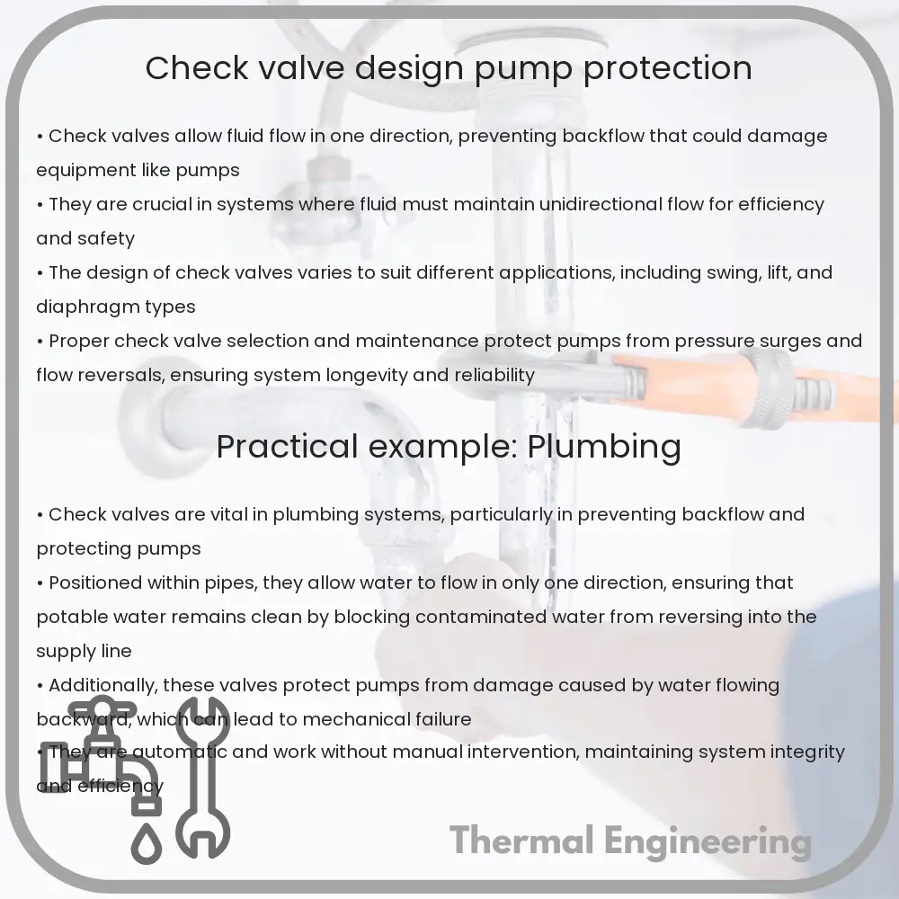
Check valves play a critical role in many fluid systems by allowing the flow of liquids or gases in one direction and preventing flow in the opposite direction. These valves are essential components in a variety of applications, including water and sewage systems, oil and gas pipelines, and HVAC systems. Not only do they contribute to the efficiency and safety of these systems, but they also protect equipment such as pumps from damage caused by backflow.

Basic Design and Operation of Check Valves

At its core, a check valve consists of a body, a seat, a disc, and a cover. The main function of the check valve is to permit flow in one direction and automatically prevent backflow when the fluid in the line reverses direction. They operate entirely by the line pressure and back pressure of the fluid being used, requiring no external control.

There are several types of check valves including:

  • Swing Check Valves: Use a swinging disc to allow or block flow. Ideal for low-pressure drop applications.
  • Lift Check Valves: Employ a lifting disc that sits on a seat. These are commonly used in high-pressure systems.
  • Dual Plate Check Valves: Feature two half-circle disks hinged together; a design that minimizes valve size and weight.
  • Ball Check Valves: Utilize a ball that seats against a round opening to stop flow.
  • Wafer Check Valves: Compact designs that are installed between two flanges.

Pump Protection Mechanisms

Pumps are integral components in many engineering systems, providing the necessary force to move liquids through pipelines. Check valves are crucial in protecting these pumps from the potential damage caused by backflow, such as:

  • Hydraulic Shock (Water Hammer): Sudden changes in water flow can lead to hydraulic shocks, damaging both pipelines and pump mechanisms. Check valves mitigate these effects by ensuring a unidirectional flow.
  • Reverse Rotation: In systems such as centrifugal pumps, the flow reversal can lead to the reverse rotation of pump impellers, which can lead to mechanical failures. Check valves prevent this scenario by blocking backflow.
  • Increased Wear: Backflow can also lead to excessive wear and tear on pump components, reducing the operational life. Check valves help in reducing the system maintenance needs by minimizing backflow.

Criteria for Choosing the Right Check Valve

Choosing the right check valve involves several factors to ensure optimal performance and durability:

  • Flow Characteristics: The nature of the flow (steady or pulsating), and the pressure and temperature of the fluid are critical parameters.
  • Materials of Construction: The materials should be compatible with the fluid to avoid corrosion. Common materials include stainless steel, brass, and PVC.
  • Installation Requirements: Some check valves, like wafer check valves, are designed for tight spaces, while others might require more room or specific orientations.
  • Maintenance Needs: Ease of maintenance and repair should be considered to ensure long-term reliability.

In conclusion, check valves are indispensable in maintaining the efficiency and protection of various mechanical systems. Whether it’s preventing the risk of water hammer or ensuring the longevity of a pumping system, the correct type of check valve will provide essential service and functionality. When selecting a valve, it’s important to consider the specific requirements of the system, including fluid properties, flow dynamics, and environmental factors.

Cyclone Separator | Design & Pollution Control

Learn about cyclone separators, devices that use vortex separation to remove particulates from streams of air, gas, or liquid without filters.

Cyclone Separator | Design & Pollution Control

Introduction to Cyclone Separators

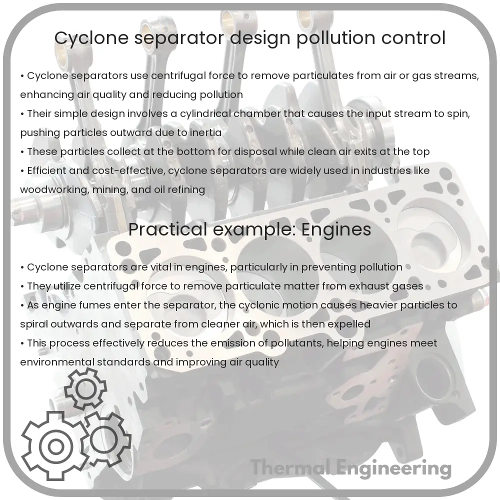
Cyclone separators are a type of technology used to remove particulates from an air, gas, or liquid stream without the use of filters, through vortex separation. Rotational effects and gravity are used to separate mixtures of solids and fluids. The method can also be used to separate fine droplets of liquid from a gaseous stream.

Basic Design of a Cyclone Separator

The typical design features a cylindrical section at the top, a conical base, and a central tube (dip tube or vortex finder) that extends from the top to the fluid outlet at the center of the cyclone. The inlet stream is introduced into the cyclone at a high velocity, usually tangentially at the top of the cylindrical section. This setup induces a rotational movement of the gas stream, creating a spiral airflow pattern downward towards the cone.

  • Body: The cylindrical top section where the inlet flow enters tangentially.
  • Cone: The tapering lower section where the separation of particles occurs under the influence of centrifugal force.
  • Vortex Finder: A tube at the center of the cyclone, this structure helps control the vortex flow, directing the clean air or gas out of the cyclone.
  • Particle Collection Area: Located at the bottom of the cone, where separated particles accumulate and are collected for disposal or further processing.

Operating Principle

In a cyclone separator, the incoming air stream, containing particulates, is injected at a high velocity into the cyclone’s cylindrical section which initiates a rapidly spinning vortex. Due to the cylindrical and conical structure, larger and heavier particles gain higher inertia than the air. Consequently, they move outward with the cyclone’s wall and downward due to gravity, finally collecting at the bottom of the cyclone. The clean air, mostly free of particulates, moves inward and upward through the vortex finder and is expelled through the outlet.

Pollution Control with Cyclone Separators

Cyclone separators are widely used in various industrial processes to remove large or dense particles from gas streams, typically in power plants, oil refineries, or manufacturing units. They are particularly effective for pollutant reduction by capturing ash, metal particles, and other substantial materials.

  • Advantages: High-efficiency for large particle removal, low maintenance, easy to operate, and capable of handling high temperatures and pressures.
  • Disadvantages: Lower efficiency for very small or lightweight particles, and can require supplemental systems like fabric filters or electrostatic precipitators for stringent emission requirements.

Enhancing Efficiency

To enhance the efficiency of cyclone separators, several modifications can be adopted. These include multiple cyclone configurations known as multiclone separators, using larger cyclone bodies for a slower gas velocity, or employing post-treatments like scrubbers or additional filters.

Conclusion

Cyclone separators play a crucial role in reducing air pollution by enabling the efficient separation of particulates from gaseous emissions. Through their simple yet effective design, they continue to be an essential component of pollution control strategies in various industries, reflecting a blend of engineering ingenuity and environmental stewardship.

Plate Heat Exchanger | Efficiency & Applications

Learn about plate heat exchangers, their operation, efficiency factors, and diverse applications in various industries.

Plate Heat Exchanger | Efficiency & Applications

Understanding Plate Heat Exchangers: Efficiency and Applications

A plate heat exchanger is a type of heat exchanger that uses metal plates to transfer heat between two fluids. This device is highly regarded for its efficiency and its ability to withstand large amounts of heat without a significant increase in size. Understanding the basic principles, efficiency factors, and applications of plate heat exchangers can provide valuable insight into this essential engineering component.

How a Plate Heat Exchanger Works

In a plate heat exchanger, fluid to be heated or cooled flows through alternating spaces between corrugated plates. The design maximizes the surface area of the plates, improving heat transfer while minimizing the space occupied. The corrugation of the plates also creates a turbulence in the fluids, which enhances the transfer of heat.

Key Factors Influencing Efficiency

  • Surface Area: Larger surface areas provide more space for heat exchange, increasing efficiency. The corrugated plates in these exchangers effectively increase the surface area.
  • Flow Configuration: The arrangement of incoming and outgoing fluids greatly affects performance. Counterflow, where fluids flow in opposite directions, is most efficient, as it can maintain a higher temperature gradient.
  • Material: Plate heat exchangers typically use metals with high thermal conductivity, such as stainless steel or aluminum, allowing efficient heat transfer.
  • Temperature and Pressure Ratings: These parameters determine the operating boundaries of the heat exchanger. Devices capable of withstanding higher pressures and temperatures typically exhibit better performance.

Applications of Plate Heat Exchangers

Plate heat exchangers are versatile and used in various industries due to their efficiency and compact nature:

  1. Chemical Industry: They are utilized for tasks like cooling, heating, or condensing chemical compounds in processes where contamination must be avoided.
  2. Food and Beverage: Used to heat or cool products gently while maintaining hygiene and preventing contamination.
  3. Power Generation: Plate heat exchangers improve thermal efficiency in power plants by recovering waste heat from exhaust gases.
  4. Marine Applications: Used in ships for engine cooling, oil cooling, and as a condenser in air-conditioning systems.
  5. HVAC Systems: They play a crucial role in district heating and cooling systems, providing efficient temperature control.

Conclusion

Plate heat exchangers represent a sophisticated design in heat transfer technology. Their ability to handle high pressure and temperature conditions efficiently and compactly makes them integral in industrial applications across the globe. As technology progresses, the expectations for more efficient and environmentally friendly heat exchange solutions grow, positioning plate heat exchangers as a crucial component in the engineering toolkit.

Whether it’s enhancing energy conservation in large industrial systems or ensuring the purity and safety of processed food, the role of plate heat exchangers continues to expand across industries, reflecting their unmatched efficiency and versatility.

Magnetic Drive Pump | Sealless, Leak Prevention

Learn about magnetic drive pumps, sealless pumps that prevent leaks by using a magnetic coupling instead of shaft seals.

Magnetic Drive Pump | Sealless, Leak Prevention

Understanding Magnetic Drive Pumps: Sealless Technology for Leak Prevention

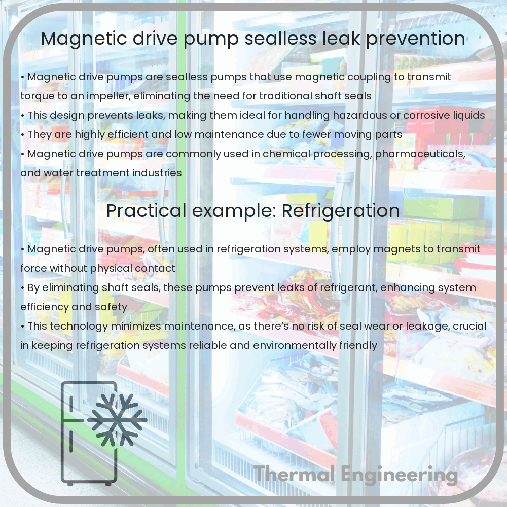
Magnetic drive pumps are a type of pump characterized by their ability to eliminate shaft seals and thus prevent leaks. This unique feature makes them particularly useful in industries where avoiding leakage of hazardous or precious fluids is critical. By exploring how magnetic drive pumps work, we can appreciate their engineering and the benefits they offer in various applications.

How Magnetic Drive Pumps Work

At the core of a magnetic drive pump’s operation is the magnetic coupling, which is composed of two parts: an outer magnet attached to the motor and an inner magnet connected to the pump’s impeller. These are separated by a rear casing that forms a hermetic seal. Unlike traditional pumps that use a mechanical seal or packing to prevent leaks from the drive shaft, magnetic drive pumps use magnetic force to transmit torque from the motor to the impeller.

When the motor is activated, the outer magnet rotates, creating a magnetic field that also causes the inner magnet to turn. This action spins the impeller, which propels the fluid through the pump. The entire mechanism is sealed off by the rear casing, ensuring that there is no direct path for the fluid to leak out.

Advantages of Magnetic Drive Pumps

  • Leak Prevention: Since there are no shaft seals that can wear out or fail, the risk of leakage is greatly minimized. This makes magnetic drive pumps ideal for handling hazardous, toxic, or corrosive chemicals.
  • Maintenance Costs: The sealless design also reduces maintenance overhead, as there are fewer parts that require regular replacement compared to pumps with mechanical seals.
  • Energy Efficiency: These pumps are generally more energy efficient. The magnetic coupling can reduce energy loss, typically making the pump perform better for the same input power.

Considerations When Choosing Magnetic Drive Pumps

Despite their numerous advantages, there are several factors to consider when implementing magnetic drive pumps:

  • Magnetic Field Limitations: The performance of the pump depends on the strength and alignment of the magnets. Misalignment or loss of magnetic material can reduce the efficiency of the pump.
  • Heat Generation: Magnetic drive pumps can generate heat due to magnetic resistance and eddy currents. Adequate cooling or heat dissipation mechanisms must be in place, especially in chemical processes where temperature control is crucial.
  • Material Selection: The materials used for the casing and other components must be compatible with the fluids being pumped to avoid corrosion or degradation, which could compromise the integrity and performance of the pump.

Applications of Magnetic Drive Pumps

Magnetic drive pumps are widely used in industries where fluid integrity is essential. These applications include:

  • Chemical Processing: Safely handling aggressive solvents, acids, and other hazardous chemicals.
  • Pharmaceuticals: Ensuring purity and preventing contamination during the manufacturing of medicines.
  • Water Treatment: Minimizing risks of leaks when dealing with treatment chemicals.
  • Oil and Gas: Transporting petrochemicals without risk of environmental contamination from leaks.

In conclusion, magnetic drive pumps offer a reliable and efficient solution for applications requiring airtight fluid handling. By removing the need for shaft seals, these pumps not only prevent leaks but also reduce maintenance requirements and operating costs. Understanding their operation and appropriate application ensures optimized performance and lifecycle benefits.

Thermal expansion mismatch in materials

Learn about thermal expansion mismatch in materials and its impact on engineering and design.

Thermal expansion mismatch in materials

Understanding Thermal Expansion Mismatch in Materials

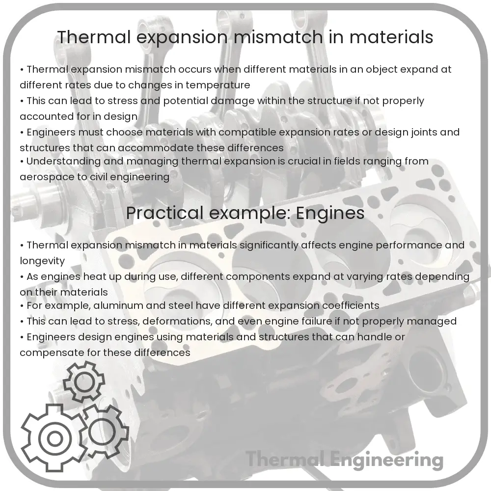
Thermal expansion refers to the tendency of material to change in volume in response to a change in temperature. When different materials are bonded together and subjected to temperature changes, mismatch in their rates of thermal expansion can lead to internal stresses, deformations, and even failure. Understanding this phenomenon is crucial in engineering applications to ensure reliability and durability of the composite structures.

Basics of Thermal Expansion

All materials expand or contract with temperature changes, albeit at different rates. This behavior is characterized by the material’s coefficient of thermal expansion (CTE), typically expressed in units of inverse temperature (e.g., 1/K). The formula given by:

ΔL = α * L0 * ΔT

  • ΔL is the change in length.
  • α is the linear coefficient of thermal expansion.
  • L0 is the original length of the material.
  • ΔT is the change in temperature.

Impact of Thermal Expansion Mismatch

When two materials with different CTEs are joined together and exposed to thermal variations, each material tends to expand or contract at its own rate, which can result in internal stresses at the interface of the materials. Common consequences of thermal expansion mismatch include:

  • Stress and Strain: As materials attempt to expand at different rates while constrained, significant mechanical stresses can build up, potentially leading to plastic deformation or even cracks.
  • Delamination: In layered materials, differing expansion rates can cause layers to separate or buckle.
  • Warping: Components can distort, losing their desired shape and structural integrity.

Applications and Considerations

Thermal expansion mismatch must be carefully considered in a variety of engineering fields, from aerospace to electronic packaging. Some typical applications include:

  1. Circuit Boards: In electronics, PCBs often involve materials like copper (high CTE) and fiberglass (low CTE). Managing their thermal mismatch is vital for preventing circuit failure.
  2. Composites: Aerospace components may use metal matrix composites where a metal is reinforced with fibers having different CTEs, necessitating designs that accommodate these differences.
  3. Concrete and Steel: Large structures like bridges and skyscrapers use concrete and steel together. Steel has about twice the CTE of concrete, which must be accounted for in their design.

Engineers often use several strategies to mitigate issues due to thermal mismatch, such as material selection, geometric design modifications, and including stress relief features within the structure.

Conclusion

Thermal expansion mismatch presents a significant challenge in the design and maintenance of many engineering systems. By understanding and anticipating the effects of differing expansion coefficients, engineers can design more reliable and durable systems that withstand temperature fluctuations in their environments.

Expansion Tank | Pressure Relief, Heating Systems

Learn about expansion tanks in heating systems, their functions, how they work, types, and sizing for maintaining system efficiency and safety.

Expansion Tank | Pressure Relief, Heating Systems

Understanding Expansion Tanks in Heating Systems and Pressure Relief

Expansion tanks are critical components in both heating systems and potable water applications, serving an essential function in maintaining pressure stability and system efficiency. This article will explore the purpose, working, and types of expansion tanks, and how they integrate into wider system operations.

What is an Expansion Tank?

An expansion tank is a small vessel used to protect closed water heating systems and domestic hot water systems from excessive pressure. The tank is partially filled with air, whose compressibility cushions shock and absorbs excess water volume created by system operation and thermal expansion.

How Do Expansion Tanks Work?

When water is heated, it expands. Without a means to compensate for this expansion, pressure in the system would continue to increase, potentially leading to pipe or component failure. The expansion tank allows the expanded water volume a place to go and prevents dangerous increases in pressure. Here’s a step-by-step look at the process:

  • Water is heated: As water heats up in a system (e.g., a boiler or water heater), it expands.
  • Pressure increase: This expansion leads to an increase in system pressure.
  • Compression of air within tank: The expanded water enters the expansion tank and compresses the air in the tank.
  • Pressure absorption: The air in the expansion tank absorbs this increased pressure, preventing any damage or excessive pressure within the main system.

Types of Expansion Tanks

There are two primary types of expansion tanks used in heating and plumbing systems:

  • Diaphragm Tanks: These tanks separate the water and air with a diaphragm. This separation helps prevent water logging of the tank by keeping the air from being absorbed into the water and maintains system efficiency.
  • Bladder Tanks: Similar to diaphragm tanks, bladder tanks contain a bladder that fully contains the air charge. Water flows around the bladder. This type too helps in maintaining the effectiveness of the air cushion and prevents the water from absorbing the air.

Calculating the Size of an Expansion Tank

The size of an expansion tank for a heating system depends on several factors including the volume of water in the system, the change in temperature, the initial pressure, and the maximum operating pressure. The basic formula to estimate the tank size is:

Volume = (V * dT * k) / (P1 – P0)

  • V is the volume of fluid in the system.
  • dT is the change in temperature.
  • k is a constant based on the fluid expansion coefficient.
  • P1 is the maximum pressure system can tolerate.
  • P0 is the pre-charge pressure of the tank.

Conclusion

Expansion tanks play a crucial role in maintaining the longevity and efficiency of heating and water systems. By understanding the basics of how these tanks work and their functions, engineers and householders can ensure their systems are both safe and effective. Regular maintenance and calculations for proper sizing can prevent system failures and optimize performance.

For further detailed readings, one might want to explore more specialized engineering texts or installation manuals provided by manufacturers of specific heating systems or expansion tanks.

Manometer | Pressure Measurement, Gas Pressure

Learn about manometers, crucial devices for measuring gas or liquid pressure in engineering and physics.

Manometer | Pressure Measurement, Gas Pressure

Understanding Manometers

A manometer is a device commonly used in engineering and physics to measure the pressure of a gas or liquid. It is particularly useful for determining the pressure based on the difference in fluid levels within its structure. Manometers are widely used due to their simplicity, accuracy, and ability to measure relatively low pressures.

Types of Manometers

There are several types of manometers, with the most common being the U-tube manometer, well-type manometer, and inclined manometer. Each type has its specific design and application niche.

  • U-Tube Manometer: This is the simplest form, consisting of a glass or plastic tube bent into a U-shape, filled with a fluid. The difference in fluid level in the two arms of the U indicates the pressure difference between the gas or liquid being measured and the atmosphere.
  • Well-Type Manometer: Similar to the U-tube but with one side of the U expanded into a large diameter well. As the pressure changes, the level in the well changes slightly, but the level in the narrower column changes significantly more, allowing for finer measurements.
  • Inclined Manometer: This type is similar to the U-tube but the measuring leg is inclined. This enhances the resolution of small changes in pressure, making it suitable for very low-pressure applications.

How It Works

The basic principle behind a manometer involves balancing the pressure exerted by a fluid (often air or gas) against the known pressure exerted by a liquid column in the manometer. The height difference (h) between the liquid levels in the manometer’s arms is directly related to the pressure difference.

The relationship can be expressed by the equation:

P1 – P2 = ρgh

Where:

  • P1 is the pressure of the gas being measured,
  • P2 is the reference pressure (often atmospheric pressure),
  • ρ (rho) is the density of the manometer fluid,
  • g is the acceleration due to gravity, and
  • h is the height difference between the fluid levels.

Applications of Manometers

Manometers are used in various fields for different purposes:

  • Engineering: In HVAC systems to measure and verify pressure conditions within ductwork or in gas supply lines.
  • Medical: Manometers are used in respiratory equipment to measure air pressure and ensure proper function.
  • Laboratory Settings: Accurate pressure measurements are crucial in experimental physics and engineering labs.
  • Weather Stations: Measuring atmospheric pressure for weather forecasting and analysis.

Advantages of Using Manometers

Manometers offer several advantages:

  • High accuracy and reliability in pressure measurement.
  • Simple construction without the need for electrical power or complicated calibrations.
  • Capability to measure a wide range of pressures.

Despite these advantages, manometers can be cumbersome for high-pressure applications and may not be suitable when rapid changes in pressure need to be measured frequently. Nonetheless, for many low-pressure applications, they remain a preferred choice for their precision and simplicity.

Conclusion

Manometers serve as a fundamental tool in the measurement and analysis of pressure in various applications across engineering, medicine, and science. Understanding their types, workings, and uses helps in leveraging this tool effectively for precise pressure determinations in professional and academic settings.