Facebook Instagram Youtube Twitter

How does a heat sink dissipate heat

Learn how heat sinks dissipate heat in electronic devices through conduction, convection, and radiation to maintain performance and longevity.

How does a heat sink dissipate heat

Understanding How a Heat Sink Dissipates Heat

Heat sinks play a crucial role in maintaining the performance and longevity of electronic devices. By effectively dissipating heat, they prevent components from overheating, which could otherwise lead to malfunction or permanent damage. But how exactly does a heat sink accomplish this critical task? Let’s dive into the principles of heat sink operation and understand its functionality in electronic systems.

Principle of Heat Transfer

A heat sink operates primarily through the process of heat transfer, where heat energy moves from a higher temperature object (such as a CPU or any other electronic component) to a cooler object (the heat sink itself). This process utilizes three primary mechanisms: conduction, convection, and radiation.

  • Conduction: This is the direct transfer of heat through a material, due to energy being passed from one molecule to another. In the case of heat sinks, heat is conducted from the device to the metallic base of the heat sink.
  • Convection: After the heat sink absorbs heat via conduction, it transfers this heat to the surrounding air via convection. This can either be natural convection, relying on the natural buoyancy of hot air to circulate, or forced convection, which involves a fan to increase air movement.
  • Radiation: Although less dominant in many applications, the heat sink also emits some energy as infrared radiation due to its elevated temperature compared to surrounding environments.

Design Features of Heat Sinks

The effectiveness of a heat sink in dispersing heat is significantly influenced by its design:

  1. Material: Heat sinks are typically made of materials with high thermal conductivity, such as aluminum or copper, to facilitate rapid heat transfer.
  2. Surface Area: Increasing the surface area available for heat transfer can be achieved by adding fins or pins to the heat sink. This allows more heat to be transferred to the air, thus enhancing the cooling effect.
  3. Fins: The design of the fins, including their number, size, shape, and spacing, affects how air flows over the heat sink and thus impacts the efficiency of heat transfer by convection.

Thermal Resistance and Its Importance

The ability of a heat sink to dissipate heat is often measured in terms of its thermal resistance, usually noted in units of °C/W (degree Celsius per Watt). Thermal resistance is the measure of the temperature difference across a heat sink per unit of power dissipated. The lower the thermal resistance, the more efficient the heat sink.

If T1 and T2 represent the temperature of the device and the ambient temperature respectively, and P represents the power dissipation, then the thermal resistance Rth can be calculated using the formula:

Rth = (T1 – T2) / P

Enhancing Heat Sink Efficiency

To increase the efficiency of heat sinks, several strategies can be employed:

  • Improving Air Flow: Using fans can significantly enhance airflow through the fins of the heat sink, which reduces the thermal resistance by increasing the rate of convection.
  • Optimizing Fin Design: Adjusting fin design and orientation to maximize air contact can greatly influence heat dissipation rates.
  • Thermal Interface Materials: Applying thermal interface materials (TIMs) between the device and heat sink can improve heat transfer by eliminating air gaps with a material that has better thermal conductivity.

Conclusion

Heat sinks are essential for cooling electronic components, and their efficiency depends on various factors including material properties, design, and environmental conditions. By understanding and optimizing these factors, the performance and durability of electronic devices can be significantly enhanced, ensuring they operate within safe temperature limits.

How does a condenser convert steam to water

Learn about condensers in this detailed guide on their role in converting steam to water in various industrial applications, focusing on their operation, components, and importance in steam power generation.

How does a condenser convert steam to water

Understanding How a Condenser Converts Steam to Water

The condenser is a critical component found in many industrial and engineering applications, most notably in steam power plants. It serves the primary function of converting gaseous steam back into its liquid form through a process known as condensation. In this article, we will explore how a condenser operates and the key principles behind its function.

The Basics of Condensation

To understand a condenser, it’s essential to start with the basics of condensation. Condensation is the process by which a gas turns into a liquid at or below its boiling point. This transformation occurs when the temperature of the vapor is reduced or when the vapor is subjected to increased pressure.

Components of a Condenser

  • Shell: The outer part that holds everything in place.
  • Tubes: A series of tubes within which the cooling medium, usually water, flows.
  • Cooling Water Inlet and Outlet: These allow for the entry and exit of the cooling medium.
  • Steam Inlet: This is where the steam enters the condenser.
  • Condensate Outlet: The point from which the converted liquid (condensate) exits the condenser.

How a Condenser Works

At its core, a condenser works by facilitating heat transfer from the steam to a cooler medium, usually water or air, thus cooling the steam and changing its phase from a gas to a liquid. Here’s a step-by-step breakdown:

  1. Intake of Steam: Steam is directed into the condenser after leaving the steam turbine. The steam enters at a lower pressure and high temperature.
  2. Cooling Process: Inside the condenser, the steam comes into contact with cooled tubes where it transfers its heat to the cooling water circulating within these tubes. This results in the cooling and eventual phase change of steam.
  3. Phase Change: As the steam loses heat, it condenses on the surface of the cold tubes. Gravity pulls the liquid, now called condensate, down to the bottom of the condenser.
  4. Extraction of Condensate: The condensed water is collected at the bottom and is removed from the condenser by a series of pumps. This water can be reused in the boiler or discharged as waste.
  5. Heat Discharge: The heat absorbed by the cooling water is either discharged to the atmosphere or sent back to the cooling tower for cooling before it is reused in the condenser.

Importance of Condensers in Steam Power Generation

In steam power plants, the condenser plays a crucial role in enhancing the efficiency of the power generation cycle. By converting the exhaust steam from turbines into water, the condenser allows this water to be reused in the boiler, thereby significantly saving on water and fuel costs. It also helps maintain a low pressure at the turbine exhaust, which maximizes turbine efficiency.

Conclusion

The engineering behind condensers is a prime example of how fundamental physics concepts like heat transfer and phase change are essential to industrial processes. Understanding the operation of a condenser provides insight into more complex systems and showcases the intricacies of thermal and mechanical engineering. Whether in power plants, refrigeration cycles, or other industrial applications, the condenser remains a key component in managing system efficiency and sustainability.

How does a hydraulic press multiply force

Learn how hydraulic presses use Pascal’s Principle to efficiently multiply force, making them essential in industries requiring heavy lifting or pressing.

How does a hydraulic press multiply force

Understanding How a Hydraulic Press Multiplies Force

A hydraulic press is a device that uses a hydraulic cylinder to generate a compressive force. It leverages Pascal’s Principle to amplify mechanical forces in an incredibly efficient way. But how exactly does a hydraulic press work to multiply force? In this article, we’ll explore the basic principles behind the hydraulic press and how it’s able to exert large forces using relatively small inputs.

The Basic Principle: Pascal’s Law

Pascal’s Law is the fundamental principle that underpins the functionality of hydraulic systems, including the hydraulic press. It states that when pressure is applied to a confined fluid, the pressure change occurs uniformly throughout the entire fluid. In mathematical terms, Pascal’s Law is expressed as:

P = F / A

Where:

  • P is the pressure applied to the fluid,
  • F is the force applied, and
  • A is the area over which the force is applied.

How a Hydraulic Press Works

A hydraulic press consists of two main components: a large cylinder and a small cylinder, connected by a pipe and filled with an incompressible fluid, usually oil. Each cylinder is fitted with a piston; the larger cylinder’s piston is the ‘output piston’, while the smaller one is the ‘input piston’.

When a force is applied to the input piston, it creates pressure in the fluid, which is then transmitted equally throughout the system. Since the output piston has a larger area, the force exerted by the fluid on this piston is greater than the force initially applied to the input piston. This is how the hydraulic press multiplies the force.

The Mathematics of Force Multiplication

The force output in hydraulic systems can be calculated using the formula derived from Pascal’s Law:

Foutput = Finput * (Aoutput / Ainput)

Where:

  • Foutput is the force exerted by the output piston,
  • Finput is the force applied at the input piston,
  • Aoutput is the area of the output piston, and
  • Ainput is the area of the input piston.

This equation shows that the ratio of the areas of the two pistons determines how much the force is multiplied. For instance, if the area of the output piston is 10 times that of the input piston, the output force will be 10 times the input force, assuming no losses due to friction or fluid leakage.

Applications of Hydraulic Presses

Hydraulic presses are widely used in various industries for applications such as:

  • Forging and shaping metals,
  • Compressing materials in waste management,
  • Forming tablets in pharmaceuticals,
  • Laminating wood and other materials.

Their ability to generate enormous forces with minimal input makes them invaluable in settings where heavy lifting or pressing is required.

Conclusion

The hydraulic press is a brilliant example of engineering that applies basic physics principles to achieve powerful results. By understanding the core principles of how these machines work, we can appreciate not only the sophistication behind their design but also their vast range of practical applications. Whether in industrial manufacturing, automotive repair, or material science, hydraulic presses play a crucial role in making heavy-duty tasks more manageable and efficient.

How does a gas turbine generate power

Learn how a gas turbine uses natural gas or other fuels to produce mechanical and electrical power through combustion and the Brayton cycle.

How does a gas turbine generate power

Understanding How a Gas Turbine Generates Power

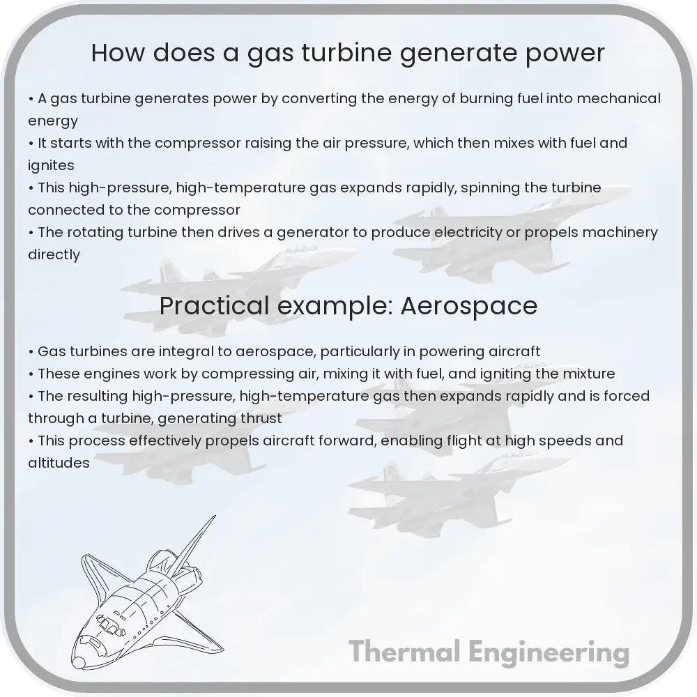
A gas turbine is a type of internal combustion engine that converts natural gas or other liquid fuels into mechanical energy. This energy then drives a generator that produces electrical power. Gas turbines are widely used in power plants, as well as in jet engines for aircraft. The basic operation involves three main components: the compressor, the combustor, and the turbine. Here’s how these components work together to produce power:

The Core Components of a Gas Turbine

  • Compressor: The compressor is the first component in a gas turbine. Its primary function is to draw in air from the atmosphere and compress it. The compressed air is then heated and pressurized, which prepares it for combustion.
  • Combustor: The high-pressure air from the compressor enters the combustor, where it is mixed with fuel. The mixture of air and fuel is then ignited. The combustion produces a high-temperature, high-pressure gas stream.
  • Turbine: The hot gases from the combustor expand rapidly and pass through the turbine blades, making them rotate. This rotation drives the compressor and also generates mechanical power which can be used to drive an electric generator.

Energy Conversion in a Gas Turbine

In essence, a gas turbine transforms the chemical energy stored in the fuel into mechanical energy through the process of combustion. The mechanical energy is then converted into electrical energy by a generator. The efficiency of a gas turbine is significantly dependent on the temperatures and pressures that it operates at, and modern turbines are capable of reaching very high efficiencies by using advanced materials and sophisticated designs.

The Brayton Cycle: The Thermodynamic Cycle

The operation of a gas turbine can be described using the thermodynamic cycle known as the Brayton cycle. This cycle consists of four primary processes:

  1. Isentropic Compression: Air is drawn into the compressor where it is adiabatically compressed (no heat is added or removed).
  2. Constant Pressure Combustion: The compressed air then enters the combustion chamber, where fuel is injected and the mixture is burned at constant pressure, significantly increasing the temperature and volume of the air.
  3. Isentropic Expansion: The high-pressure, high-temperature gas expands through the turbine, performing work on the turbine blades as it does so. This process is also adiabatic.
  4. Pressure Drop Across the Exhaust: Finally, the exhaust gases are expelled through the exhaust duct at atmospheric pressure, completing the cycle.

The efficiency of the cycle improves with higher compression ratios and higher turbine inlet temperatures, but these are limited by the materials used in turbine construction.

Applications and Benefits

Gas turbines are exceedingly useful in a variety of applications. Not only are they critical in providing thrust for jet engines, but they are also essential in generating rotary power for different industrial purposes. In power generation, gas turbines are valued for their quick start-up times and scalability. They can be used for peaking power during high demand periods and are also effective in cogeneration (combined heat and power) setups due to their ability to produce both electrical and thermal energy simultaneously.

Conclusively, the gas turbine is a pivotal component in various engineering fields, showcasing an exemplary application of thermodynamic principles to generate power efficiently and reliably.

How does refrigerant cycle in an AC system

Learn how the refrigerant cycle, crucial to air conditioning, manages heat transfer and phase changes to cool environments.

How does refrigerant cycle in an AC system

Understanding the Refrigerant Cycle in an Air Conditioning System

The refrigerant cycle, also known as the vapor-compression cycle, is the heart of any air conditioning system. It is a process that removes heat from an enclosed area and expels it into the environment, keeping our homes and vehicles cool. This cycle relies on the physical properties of a refrigerant, a substance easily convertible between liquid and gaseous states. Let’s explore each step of this cycle to understand how an air conditioner operates.

Key Components of the Refrigerant Cycle

  • Compressor: Compresses the refrigerant, raising its pressure and temperature.
  • Condenser: A series of coils in which the high-pressure vapor refrigerant releases heat and turns into liquid.
  • Expansion Valve: Reduces the pressure of the refrigerant, which cools it down.
  • Evaporator: Coils that absorb heat from the environment, causing the refrigerant to evaporate from liquid to gas.

The Stages of the Refrigerant Cycle

  1. Compression:

    The compressor sucks in the low-pressure refrigerant gas from the evaporator and compresses it. This compression increases the refrigerant’s pressure and temperature, transforming it into a high-pressure hot gas.

  2. Condensation:

    The hot, high-pressure refrigerant gas moves through the condenser coils. Here, the refrigerant releases its heat to the outside air. As it loses heat, the refrigerant condenses and turns into a high-pressure liquid.

  3. Expansion:

    The high-pressure liquid refrigerant then reaches the expansion valve. The valve restricts the flow of the refrigerant, causing a dramatic drop in its pressure. This process also reduces the refrigerant’s temperature, turning it into a cool, low-pressure liquid.

  4. Evaporation:

    The cool, low-pressure liquid refrigerant enters the evaporator coils. Here, it absorbs heat from the indoor air and begins to evaporate. The absorption of heat cools the air inside the room or vehicle. The refrigerant, now back to a low-pressure gas, returns to the compressor to repeat the cycle.

Heat Transfer and Phase Changes

The efficiency of an air conditioning system depends on the thermodynamic properties of the refrigerant and the design of the components. Throughout the cycle, the refrigerant undergoes various phase changes, shifting from gas to liquid and back. These changes are pivotal, as they allow the refrigerant to absorb and release heat efficiently. The cycle’s phase changes are driven by the laws of thermodynamics, specifically the principles of heat transfer and the conservation of energy.

Conclusion

The refrigerant cycle is a brilliant demonstration of engineering applied to improve everyday life. By harnessing the properties of the refrigerant and the laws of physics, air conditioning systems keep our environments comfortably cool. Understanding this cycle not only helps in appreciating modern conveniences but also underscores the importance of thermodynamics in practical applications.

Whether it’s a sweltering summer day or a humid night, the refrigerant cycle in air conditioners plays a crucial role in providing comfort and improving the quality of life.

How does a centrifugal pump move fluid

Learn how a centrifugal pump uses rotational energy from a motor to move fluids effectively through the conversion of kinetic energy and centrifugal force.

How does a centrifugal pump move fluid

Understanding How a Centrifugal Pump Moves Fluid

Centrifugal pumps are among the most commonly used pumps in various applications, from water supply to industrial settings. Understanding how they work not only enlightens us on a key piece of engineering but also demystifies one of the fundamental machines in fluid management systems.

The Basic Principle

At its core, a centrifugal pump converts rotational energy, typically from a motor, into energy in a moving fluid. The main parts of the pump include the impeller, pump casing, and the shaft. The process by which a centrifugal pump moves fluid involves several steps rooted in the laws of physics, particularly the principles of kinetic energy and centrifugal force.

Components of a Centrifugal Pump

  • Impeller: The impeller is a rotating part of the centrifugal pump that transfers energy from the motor to the fluid. It usually consists of a series of curved vanes fitted onto a central hub.
  • Casing: The casing is the enclosed structure that surrounds the impeller. It is designed to contain the fluid and guide it from the impeller to the pump discharge point, typically having a spirally shaped path that helps increase fluid speed and pressure progressively.
  • Shaft: This is connected to the impeller and driven by a motor. It transmits the rotational motion to the impeller.

Operating Mechanism

The operation of a centrifugal pump is centered around the impeller and the conversion of mechanical energy into fluid velocity. The process is as follows:

  1. Rotation and Suction: As the impeller rotates, it imparts kinetic energy to fluid particles that enter the pump suction or inlet. This rotation also creates a low-pressure area at the eye (center) of the impeller causing fluid to be drawn into the pump.
  2. Increase in Fluid Velocity: The fluid enters the impeller along its axis and is moved radially outward by the centrifugal force created by the rotation of the impeller.
  3. Conversion of Energy: As the fluid moves through the impeller and into the pump casing, its velocity increases and along with it, the dynamic pressure of the fluid also increases. The shape of the casing converts the high velocity of the fluid into high pressure by slowing the fluid through a diffuser or volute.
  4. Discharge: The high-pressure fluid then exits the pump through the discharge port where it can be directed to the desired location in a system.

Mathematical Background

The conservation of energy in a centrifugal pump can be described by the Bernoulli Equation across the pump, which in its simple form is:

Pressurein + 1/2 * ρ * (Velocityin)2 + ρghin = Pressureout + 1/2 * ρ * (Velocityout)2 + ρghout

Here, ρ represents the fluid density, g is acceleration due to gravity, h is height above a reference plane, and v is velocity of fluid. In centrifugal pumps, typically, the velocity at the pump inlet is much less than at the outlet, signifying energy transferred to the fluid.

Conclusion

Centrifugal pumps are crucial for moving fluids across various sectors due to their ability to efficiently enhance the kinetic energy of fluids. Through the conversion of rotational kinetic energy into the fluid dynamic energy, centrifugal pumps meet a broad array of operation requirements, from low-viscosity fluids like water to complex industrial liquids.

How does a jet engine work

Learn how jet engines function as the key drivers of modern aviation, from basic operations to advanced technological improvements.

How does a jet engine work

Understanding Jet Engines: The Power Behind Modern Aviation

Jet engines are at the heart of modern aviation, propelling everything from commercial airliners to military fighters across the sky. Despite their complexity, the basic principle behind how a jet engine works can be understood by examining their core functions and components.

The Basics of Jet Engine Operation

A jet engine operates on the principle of Newton’s Third Law of Motion: “For every action, there is an equal and opposite reaction. Air is sucked in at the front, compressed, mixed with fuel, ignited and then blasted out at the back, propelling the aircraft forward.

Key Components of a Jet Engine

  1. Intake – Air enters the engine through an intake, which is designed to direct the flow of air into the engine efficiently while minimizing drag.
  2. Compressor – The compressor increases the pressure of the incoming air, preparing it to mix with fuel for combustion. Compressors are typically made up of multiple stages of small, rotating blades.
  3. Combustor – In this chamber, the high-pressure air mixes with fuel, usually jet fuel, and is ignited. The combustion significantly increases the temperature and energy of the gas.
  4. Turbine – The high-energy gas then flows through the turbine, which extracts some of this energy to drive the compressor and other accessories attached to the engine.
  5. Exhaust – The heated, high-pressure gas exits the engine through the exhaust, creating thrust as it escapes. This is the action that results in a reaction that pushes the jet forward.

The Physics of Jet Propulsion

The thrust generating process in a jet engine can be understood through the fundamental equation of momentum in fluids:

Force = Mass flow rate * (Exit velocity – Entry velocity)

In the context of a jet engine, as air moves through the engine, it is compressed, mixed with fuel, ignited, and then expelled at a higher velocity than when it entered. This increase in velocity results in a jet of exhaust gases shooting backward, propelling the engine, and therefore the aircraft, forward.

Types of Jet Engines

There are several types of jet engines, adapted for different purposes:

  • Turbojet – The simplest type of jet engine, with all engine components aligned in a straight line. Ideal for high-speed aircraft at high altitudes.
  • Turbofan – Most common in commercial airliners, turbofans have a fan at the front that forces cold air around the outside of the combustion chamber, producing additional thrust and improving efficiency.
  • Turboprop – These engines use a gas turbine to drive a propeller, making them efficient at lower speeds and suitable for smaller aircraft like commuters and transport planes.
  • Turbo shaft – Similar to turboprops, turboshaft engines are primarily used in helicopters, driving the rotor blades rather than a prop.

Advancements in Jet Engine Technology

Recent advancements in jet engine technology often focus on improving efficiency and reducing emissions. Manufacturers are developing engines with higher bypass ratios and better thermal efficiencies. Innovations like noise-reducing technologies and the use of sustainable aviation fuels are also becoming more prevalent, driven by global demands for environmentally friendly air travel.

Conclusion

Jet engines are marvels of engineering that combine aerodynamics, thermodynamics, and mechanical design to create the thrust needed for flight. Understanding how these engines work not only gives us insight into a crucial aspect of modern transportation but also illuminates the ways in which physics and engineering converge to solve complex, real-world challenges.

By grasping the fundamental principles behind jet engines, we can appreciate the scientific ingenuity and technological advancements that allow us to soar above the clouds.

Heat transfer in biological systems

Learn how heat transfer in biological systems impacts organism physiology and environmental interactions through conduction, convection, and radiation.

Heat transfer in biological systems

Understanding Heat Transfer in Biological Systems

Heat transfer in biological systems is a fundamental aspect of physiology and environmental interactions. It involves the exchange of thermal energy between organisms and their surroundings, and within the bodies of the organisms themselves. This process is vital for the maintenance of optimal body conditions that support life processes.

Modes of Heat Transfer

There are three primary modes of heat transfer: conduction, convection, and radiation. Each plays a crucial role depending on the organism and its environment.

  • Conduction is the transfer of heat through direct contact. In biological systems, this can occur when an animal lies on a cool surface to lower body temperature or when internal heat is conducted to the body surface and then dissipated.
  • Convection involves the movement of heat by the physical movement of fluid (which can be air or liquid). For example, blood circulation helps distribute heat from core regions of the body to the skin where heat can be lost to the environment.
  • Radiation refers to the emission or absorption of infrared heat. Animals, including humans, radiate heat to the environment and absorb radiative heat from the sun or other sources.

Biological Implications of Heat Transfer

The efficiency and direction of heat transfer can significantly affect an organism’s energy balance and thermoregulation. Thermoregulation is the ability of an organism to maintain its body temperature within certain boundaries, even when the surrounding temperature is very different. This can involve behavioral strategies, such as seeking shade or sun, and physiological mechanisms like altering blood flow or sweating.

Heat Transfer Equations and Biological Application

To quantitatively describe heat transfer in biological systems, several equations are commonly used. The Fourier’s Law of Heat Conduction, for instance, is expressed as:

q = -k * A * \(\frac{\Delta T}{\Delta x}\)

where

  • q is the heat transfer rate,
  • k is the thermal conductivity of the material,
  • A is the cross-sectional area through which heat is being conducted,
  • \(\Delta T\) is the temperature difference,
  • \(\Delta x\) is the thickness of the material.

In biological terms, this could refer to how heat moves through tissue or across skin layers.

Role of Evaporative Cooling

Evaporative cooling is another critical heat transfer mechanism in organisms, particularly in humans and many large mammals. This process involves the conversion of water from liquid to vapor, which absorbs a significant amount of energy (heat) from the skin, thereby cooling the body. The heat of vaporization (enthalpy of vaporization) of water is very high, around 2260 kJ/kg, which makes sweating an effective cooling process under hot conditions or intense physical activity.

Challenges and Adaptive Strategies

Organisms often face environmental challenges that test their ability to manage heat transfer. Extremes of temperature, high levels of solar radiation, and high humidity can impair the mechanisms of heat loss, leading to thermal stress. In response, many species have evolved specialized structures, behaviors, and physiological traits that optimize heat exchange and protect their vital functions. Examples include the large ears of African elephants that enhance heat loss through convection, and the burrowing habits of desert rodents that avoid heat gain during the hottest parts of the day.

Understanding heat transfer in biological systems not only elucidates how organisms interact with their environments but also enriches our approach to biomedical engineering, conservation efforts, and climate change research, highlighting the interconnectedness of life and physical processes.

How does nuclear fission produce energy

“Nuclear fission” is a process where an atom’s nucleus splits into smaller parts, releasing neutrons and significant energy, primarily used in nuclear power plants for electricity generation.

How does nuclear fission produce energy

How Does Nuclear Fission Produce Energy?

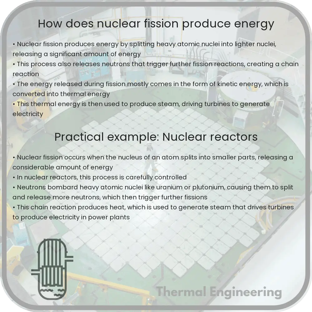
Nuclear fission is a process where the nucleus of an atom splits into two smaller nuclei along with a few neutrons and a large amount of energy. This fundamental reaction is the core mechanism used in nuclear power plants to produce electricity. Let’s explore how this significant energy release occurs and how it is harnessed to generate power.

Understanding the Fission Process

In nuclear fission, a heavy nucleus absorbs a neutron, becoming unstable and dividing into two new nuclei. This process can be represented by a simple equation for the fission of uranium-235 (U-235), one of the most common fuel isotopes in nuclear reactors:

235U + n → 142Xe + 91Sr + 3n + Energy

Here, a uranium-235 nucleus absorbs a neutron (n), and splits into xenon-142 (Xe-142), strontium-91 (Sr-91), and releases three more neutrons plus a considerable amount of energy.

Release of Energy

The energy released during fission comes primarily from the nuclear strong force, a fundamental force that binds the particles (protons and neutrons) in the nucleus together. When the nucleus splits, the strong force acts over a smaller range, and the excess binding energy is expelled. This energy is emitted in several forms:

  • Kinetic Energy of Fission Fragments: The fission fragments (the smaller nuclei) are driven apart by repulsive forces and move away at high speeds, carrying kinetic energy.
  • Gamma Rays: High-energy gamma rays are released, carrying away energy in the form of electromagnetic radiation.
  • Neutron Release: Additional neutrons are emitted, which can propagate the fission process in a chain reaction.
  • Beta Particles: Some of the fission products are radioactive and undergo beta decay, releasing beta particles and more gamma rays.

Harnessing Fission Energy in Nuclear Reactors

In a nuclear reactor, the fission process is carefully controlled to manage the energy release. The core of a nuclear reactor contains the fuel (usually enriched uranium or plutonium), which is arranged in rods to maintain a controlled chain reaction. Here’s how the process works:

  1. Initiation: Neutrons are introduced to the reactor core, absorbing into the fuel nuclei to begin the fission process.
  2. Control: Control rods made of materials like cadmium or boron absorb excess neutrons to ensure the chain reaction does not accelerate uncontrollably.
  3. Heat Production: The kinetic energy of the fission fragments is transferred to the surrounding reactor coolant (water or gas), heating it up.
  4. Steam Generation: The heated coolant generates steam in boilers or steam generators.
  5. Electricity Generation: The steam drives turbines connected to generators, producing electricity.

Heat exchanged in the reactor is thus converted into mechanical energy via the turbines and finally into electrical energy by the generators.

Significance and Challenges

Nuclear fission provides a powerful source of energy that can generate large amounts of electricity without the carbon emissions associated with fossil fuels. However, it also presents significant challenges, including managing radioactive waste, ensuring reactor safety to prevent accidents, and political and social concerns relating to the use of nuclear technology.

In conclusion, nuclear fission is a complex yet fascinating process that highlights the intricate interplay of physics in power generation, providing a substantial portion of the world’s energy with its unique set of pros and cons.

Principles of Fluid Stratification

Understand fluid stratification, its causes like thermal and haline differences, and its impact on environments and engineering.

Principles of Fluid Stratification

Understanding Fluid Stratification: Basics and Importance

Fluid stratification is a fundamental principle in the field of fluid dynamics, which plays a critical role in both natural environments and engineering applications. It refers to the formation of layers within a fluid, where each layer has different properties such as density, salinity, or temperature. This phenomenon affects everything from weather patterns and ocean currents to the efficiency of industrial processes.

What Causes Fluid Stratification?

The primary cause of fluid stratification is the variation in density between different parts of a fluid. Density differences can arise due to variations in temperature (thermal stratification), salinity (haline stratification), or both (thermohaline stratification). For example:

  • Thermal stratification: Warmer water is less dense and tends to sit above cooler, denser water.
  • Haline stratification: Fresh water is less dense than salt water, leading to stratification in bodies of water where these two meet.

These variations in density can create distinct layers, or strata, which are separated by thin transition zones known as pycnoclines.

Mathematical Description of Fluid Stratification

The stability of fluid stratification can often be analyzed using the Richardson number (Ri), a dimensionless number that expresses the ratio of potential energy due to the density gradient to the kinetic energy of the fluid flow. It is given by:

\[ Ri = \frac{g \Delta \rho h}{\rho_0 u^2} \]

Here:

  • \( g \) is the acceleration due to gravity,
  • \( \Delta \rho \) is the density difference between the layers,
  • \( h \) is the thickness of the layer,
  • \( \rho_0 \) is the reference density, and
  • \( u \) is the flow speed of the fluid.

A high Richardson number indicates a stable stratification, while a low value suggests that turbulence or mixing is likely to occur.

Applications and Implications of Fluid Stratification

Fluid stratification has significant implications across various fields:

  1. Environmental Science: Stratification can affect the oxygen levels in water bodies, impacting aquatic life and ecosystem health. It also influences the behavior of pollutants in the atmosphere and oceans.
  2. Weather Forecasting: The understanding of thermal stratification plays a critical role in predicting weather patterns, including the formation of fog and thunderstorms.
  3. Engineering: In chemical engineering, stratification must be managed in processes involving the mixing of fluids with different densities. Similarly, in mechanical engineering, the design of HVAC systems relies on understanding air stratification in enclosed spaces.
  4. Energy Production: In the context of renewable energy, thermal stratification in solar ponds enhances the efficiency of storing solar energy as heat.

In summary, fluid stratification is a vital concept that aids in understanding not just environmental and weather-related phenomena, but also a variety of engineering challenges. By studying how different layers of fluids interact based on their properties, scientists and engineers can devise more effective strategies in technology and environmental management.

Conclusion

Fluid stratification, by shaping the dynamics of natural and engineered systems alike, underscores the interconnectedness of physical principles with real-world applications. A thorough grasp of these concepts enhances the ability to innovate and optimize in fields ranging from environmental science to mechanical and chemical engineering.