Facebook Instagram Youtube Twitter

How does a cyclone separator work

Learn about cyclone separators, devices that efficiently separate particles from gas or liquid streams using vortex separation without filters.

How does a cyclone separator work

Understanding Cyclone Separators

A cyclone separator, often simply called a cyclone, is a device used to separate particles from a gas or liquid stream without the use of filters, through vortex separation. Rotational effects and gravity are used to separate mixtures of solids and fluids. The method can also be used to separate fine droplets of liquid from a gaseous stream.

Basic Principle and Design

A high-speed rotating airflow is established within a cylindrical or conical container called a cyclone. Air flows in a spiral pattern, starting at the top (wide end) of the cyclone and ending at the bottom (narrow end) before exiting the cyclone in a straight stream through the center of the cyclone and out the top. Larger particles in the rotating stream have too much inertia to follow the tight curve of the stream and strike the outside wall, then fall to the bottom of the cyclone where they can be removed.

Components of a Cyclone Separator

  • Inlet: The body of the cyclone is fitted with an inlet valve where the particle-laden stream enters.
  • Cylindrical body: The main body of the cyclone where the vortex is created, and where separation takes place.
  • Conical section: The tapered part of the cyclone that helps to compress and concentrate the particle matter.
  • Outlet Pipe (Vortex finder): A tube that extends into the top of the cyclone, through which the cleaned gas exits.
  • Particle collection area: Located at the bottom of the cyclone, where the separated particles are collected and removed.

Operation Mechanism

The working mechanism of a cyclone separator can be summarized in the following steps:

  1. The particle-laden airstream enters the cyclone separator at the inlet. This air is guided to move in a spiral motion.
  2. Due to the shape of the cyclone and the swirling motion imposed by the cyclone’s design, a “vortex” is created.
  3. Larger and heavier particles in the stream can’t follow the tight curvature of the air stream and collide with the wall of the cyclone. Upon hitting the wall, these particles lose momentum and fall down into the collection area due to gravity.
  4. Meanwhile, the cleaned air, or the air stream with significantly reduced particle content, moves upwards in a tighter inner spiral and exits through the outlet pipe.

Applications and Efficiencies

Cyclone separators are widely used in various industries because they are easy to operate, maintain, and are cost-effective. Some common areas where cyclone separators are employed include:

  • Mining Industry: To separate particles from extracted materials.
  • Pollution Control: To remove particulates from industrial flue gases or dust from air streams in factories.
  • Agriculture: In grain handling facilities to remove dust and other impurities from the air.
  • Manufacturing: For the separation and recovery of product from mist or dust-laden air.

The efficiency of cyclone separators depends on multiple factors including the size and density of the particulates, the cyclone’s design, and the volume of airflow. Sized properly and with appropriate velocities, typical efficiencies for fine particulates can range from 70% to 90%.

Conclusion

Cyclone separators offer a mechanical method of separating particulates from gases or liquids without requiring expensive filters or complex mechanisms. By leveraging basic principles of physics such as rotational dynamics and gravity, cyclone separators provide an efficient and sustainable solution in various industrial processes.
How does an evaporator remove moisture

Learn about evaporators, essential devices used in industrial processes and HVAC systems to efficiently remove moisture by exploiting the physics of boiling points and pressure.

How does an evaporator remove moisture

Understanding How an Evaporator Removes Moisture

An evaporator is an essential component in various industrial processes and HVAC (Heating, Ventilation, and Air Conditioning) applications, primarily used to extract moisture from a fluid mixture or air. This device operates on fundamental principles of thermodynamics and mass transfer, providing efficient results in moisture removal, which is crucial for many system operations such as refrigeration, air conditioning, and food processing.

Basic Principle

The primary function of an evaporator is to exploit the physical properties of the liquid’s boiling point and the surrounding air’s partial pressure to remove moisture. By changing the pressure or temperature within the system, the evaporator can convert the liquid component of a solution or air into its gaseous form, leaving behind less volatile components, primarily solids or denser liquids.

Types of Evaporators

  • Dry Expansion Evaporator: Used in refrigeration, where the refrigerant absorbs heat upon vaporization.
  • Flooded Evaporator: Immerses cooling coils in the liquid to be chilled, enhancing heat transfer efficiency.
  • Falling Film Evaporator: Distributes the liquid to be evaporated over a vertical, heated tube bundle with gravity pulling the film down while it evaporates.
  • Forced Circulation Evaporator: Employs a pump to circulate the liquid continuously, generally used for viscous liquids or those with suspended solids.

Evaporation Process

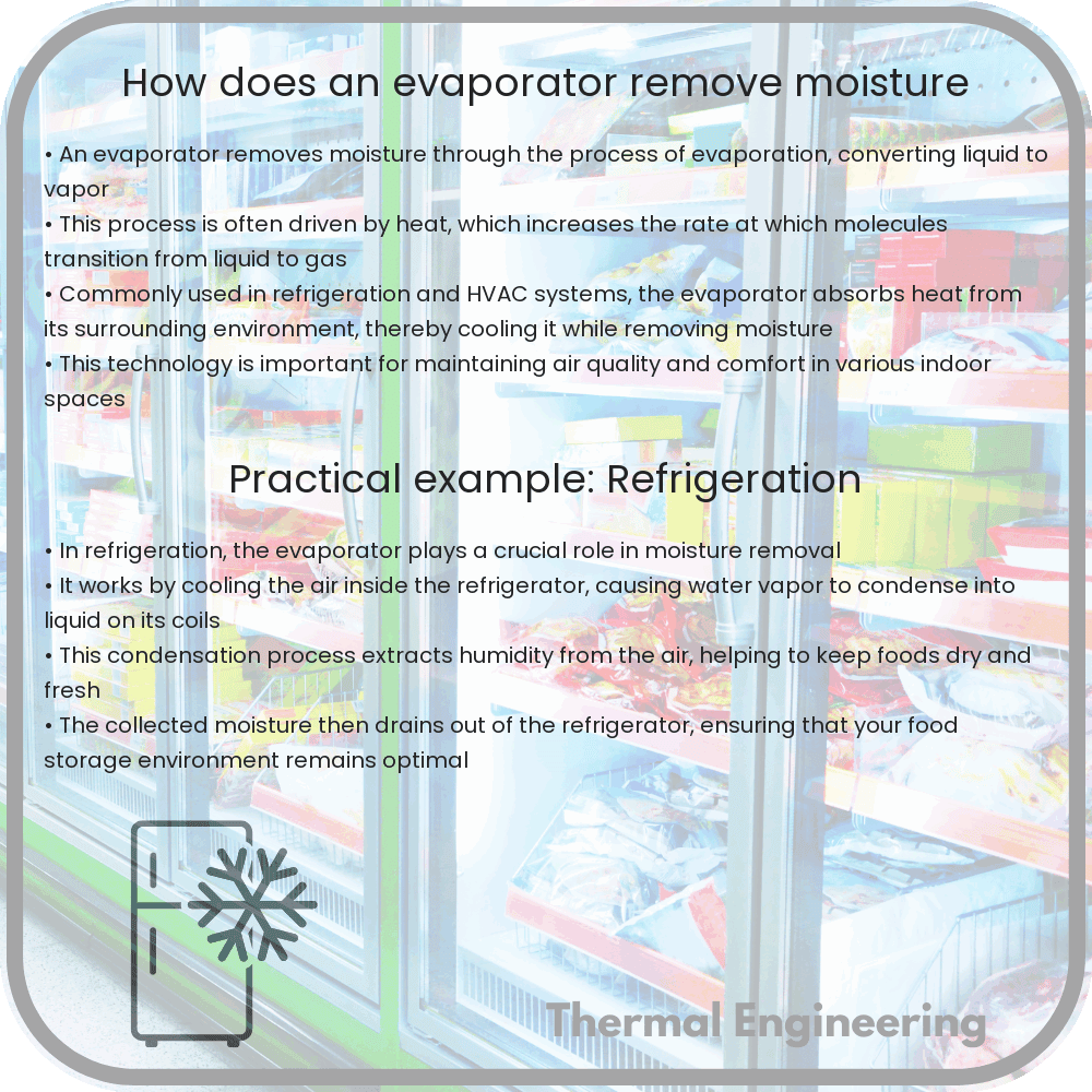
In the typical operation of an evaporator, the process begins with the feeding of the solution or moist air into the evaporator. If the application involves the removal of moisture from air, as in HVAC systems, the air passes over a set of coils containing a refrigerant at low pressure. This causes the refrigerant to absorb heat from the air, reducing its temperature below the dew point, thereby condensing water vapor into liquid droplets that are collected and removed.

For liquid mixtures, the process involves heating the mixture until the volatile solvents or water begin to vaporize. This can be induced by direct heating or reducing the pressure within the evaporator (using a vacuum), which lowers the boiling temperature of the liquid.

Mathematical Understanding

The efficiency and design of an evaporator can be understood more accurately through mathematical analysis, primarily using the heat transfer and mass transfer principles. The fundamental equation governing the evaporation process in terms of heat transfer is represented as:

Q = mlv * Hfg

  • Q represents the heat input required for the evaporation process.
  • mlv is the mass flow rate of the liquid vaporized.
  • Hfg is the latent heat of vaporization of the fluid.

This equation helps predict the amount of energy required to vaporize a specific mass of liquid and can be critical for designing energy-efficient evaporators.

Applications

Evaporators play a critical role in numerous fields:

  • In air conditioning systems, they extract humidity from the air, providing comfort and preventing mold growth.
  • In food processing, such as in the production of concentrated fruit juices, evaporators remove excess water.
  • In chemical processing, they are used to concentrate solutions, reducing the solvent volume and increasing product purity.
  • In waste water treatment, evaporators can remove water from waste streams, reducing the volume of waste and recovering water for reuse.

In conclusion, evaporators are versatile units that leverage fundamental engineering principles to remove moisture. By understanding and applying these principles, engineers can design systems that are both effective and efficient, across various industries.

How does a geothermal heat pump work

Learn how geothermal heat pumps use underground temperatures for efficient building heating and cooling.

How does a geothermal heat pump work

Understanding How a Geothermal Heat Pump Works

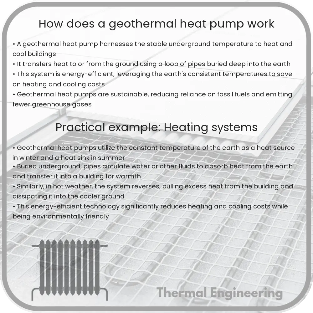
Geothermal heat pumps, also known as ground-source heat pumps, are highly efficient renewable energy systems that leverage the stable underground temperature to heat and cool buildings. The principles behind geothermal heat pumps are based on transferring heat, rather than producing it through combustion, making them an environmentally friendly alternative to conventional systems.

Basic Principle

The earth beneath our feet maintains a nearly constant temperature between 10°C and 16°C (50°F and 60°F), depending on geographic location, regardless of the climate at the surface. Geothermal heat pumps exploit this constant temperature to exchange heat between your home and the earth through a series of loops containing a fluid. This system can be used both for heating and cooling purposes.

Components of a Geothermal Heat Pump System

  • Heat Pump Unit: This is the central system that handles the heat exchange and distributes the conditioned air through the building.
  • Heat Exchanger (Loop System): A network of pipes buried in the ground near the building. It can be installed either vertically or horizontally, depending on the space available. The loop is filled with a mixture of water and antifreeze.
  • Distribution System: Consists of ductwork through which the heated or cooled air is forced into the building.

Heating Mode

In heating mode, the geothermal heat pump extracts heat from the ground via the loop system. The fluid in the loops absorbs the earth’s natural heat and is then pumped back to the heat pump unit. Here, the heat pump elevates the temperature of the absorbed heat through a process involving a compressor and a heat exchanger. This warmed air is then channeled through the distribution system into the building.

Cooling Mode

Conversely, in cooling mode, the process is reversed. The indoor heat is absorbed by the heat pump and transferred to the fluid in the loops, which is then circulated underground. The earth serves as a heat sink, where it absorbs and dissipates the heat. The cooled fluid returns to the heat pump to cool the air, which is then distributed throughout the building.

Efficiency and Environmental Impact

Geothermal heat pumps are recognized for their efficiency and sustainability. They significantly reduce the need for electric heating or cooling, leading to lower utility bills and reduced greenhouse gas emissions. According to the United States Environmental Protection Agency, geothermal heat pumps can reduce energy consumption—and corresponding emissions—up to 44% compared to air-source heat pumps, and up to 72% compared to electric resistance heating with standard air-conditioning equipment.

Moreover, the installation of geothermal heat pump systems can qualify homeowners for various federal or state grants and tax incentives, further enhancing their economic benefits.

Conclusion

Geothermal heat pumps offer a reliable, efficient, and sustainable solution for building climate control. By harnessing the stable temperatures of the earth, these systems provide heating and cooling solutions that are not only cost-effective in the long run but also contribute positively to reducing environmental impact. The initial cost and ground disturbances for loop installation are considerations, but the long-term benefits help offset these challenges.

In an era where sustainability is paramount, geothermal heat pumps illustrate a fruitful merger of natural sciences and engineering innovation, delivering a pragmatic solution to energy and climate needs.

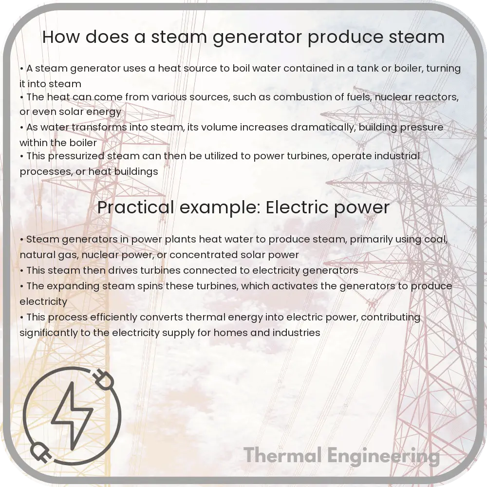
How does a steam generator produce steam

Learn how a steam generator converts water into steam, its core components, operation principles, and importance in industrial applications.

How does a steam generator produce steam

Understanding the Mechanics Behind a Steam Generator

Steam generators are vital components used in various industrial and power-generation applications. The fundamental purpose of a steam generator is to convert water into steam using heat energy. This equipment plays a crucial role in creating the high-pressure steam necessary for driving turbines in power plants, sterilizing medical instruments, and performing many other industrial processes. This article explores the basic principles and operations of a steam generator.

Core Components

At its most basic level, a steam generator consists of the following main components:

  • Boiler: The key component where water is transformed into steam.
  • Burner: Used for heating up the water by burning fuel, which could be oil, gas, or coal.
  • Control system: Regulates the temperature, pressure, and flow of steam and water.
  • Feedwater pump: Pumps water into the boiler from the external source to be converted into steam.
  • Economizer: A heat exchanger that increases the efficiency of the generator by warming up the incoming water using waste heat from the exhaust gases.

Operation Principle

The operation of a steam generator involves several critical steps:

  1. Water Introduction: Feedwater is introduced into the system using a high-pressure pump that transports the water into the boiler.
  2. Heating and Evaporation: In the boiler, the incoming water absorbs the heat produced by the burning of fuel, which raises the water’s temperature until it reaches boiling point and begins to evaporate.
  3. Steam Separation: As the water turns into steam, it rises due to the reduction in its density. The design of the boiler allows for steam, being lighter than water, to be collected at the top and drawn off for use in processes or power generation.
  4. Superheating: In many applications, it is desirable to increase the temperature of the steam beyond its saturation temperature to increase efficiency, a process known as superheating.

Energy Transfer and Conversion

The conversion of water to steam involves the basic principles of heat transfer and thermodynamics. When heat is added to water at the boiling point, it doesn’t raise the water’s temperature but rather changes its state from liquid to vapor. This process requires an amount of energy called the enthalpy of vaporization. The general equation for the energy required to convert water into steam can be written as:

E = m * Hv

Where:

  • E is the energy required,
  • m is the mass of the water, and
  • Hv is the enthalpy of vaporization.

Importance in Engineering

Steam generators are fundamental in multiple branches of engineering, especially in mechanical and chemical engineering. They are integral parts of thermal power stations, refining processes, and manufacturing industries. Their design and operational efficiency directly affect the process efficiency, operational costs, and environmental impact of the facilities they serve.

Understanding how a steam generator works provides essential insight into much of today’s industrial infrastructure and technological advancements in energy efficiency and production processes. This knowledge helps pave the way for innovations in engineering applications and the optimization of systems that rely on steam generation.

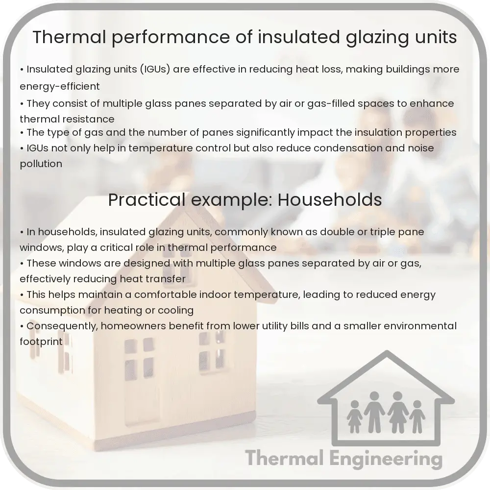
Thermal performance of insulated glazing units

Learn about insulated glazing units (IGUs), including their design and how they enhance building energy efficiency through advanced technologies and materials.

Thermal performance of insulated glazing units

Understanding the Thermal Performance of Insulated Glazing Units

Insulated glazing units (IGUs), commonly known as double glazing or triple glazing, are crucial components in energy-efficient building designs. These units significantly impact a building’s thermal insulation, helping reduce energy consumption for heating and cooling. By exploring how these units work and their effectiveness, we can appreciate their role in sustainable engineering practices.

Basics of Insulated Glazing Units

Insulated glazing units consist of two or more glass panes separated by a space filled with air or inert gases like argon or krypton. These panes are sealed around the edges to create a closed system. The main factors contributing to the thermal performance of IGUs include:

  • The number of glass panes
  • Type of gas used in the spacer
  • Thickness of the air or gas layer between the panes
  • Type of glass and coatings on the glass

Role of Gas Fills

The choice of gas between the panes is instrumental in enhancing insulation. Heavier gases like argon (Ar) and krypton (Kr) are preferred due to their lower thermal conductivity compared to air. For instance, argon gas reduces thermal conductivity more effectively because it is denser than air, providing better insulation properties.

Spacer Technology

The spacers, which keep the glass panes apart, also play a key role in the thermal performance of IGUs. Traditionally, spacers were made of aluminum, but today’s high-performance IGUs often feature warm-edge spacers made from materials like stainless steel or composites that have lower thermal conductivity, thereby reducing heat loss at the edges of the glass.

Low-Emissivity Coatings

Low-emissivity (Low-E) coatings are microscopically thin, transparent layers of metal or metal oxide deposited on one or more of the glass surfaces. These coatings reduce the U-factor by suppressing radiative heat flow, reflecting interior temperatures back inside during winter and blocking external heat in summer, thus improving the unit’s overall energy efficiency.

Calculating the Thermal Performance

The thermal performance of insulated glazing units is commonly expressed using the U-factor (thermal transmittance). The U-factor is the rate at which a window, door, or skylight conducts non-solar heat flow. It’s generally measured in watts per square meter Kelvin (W/m2K). The lower the U-factor, the better the window insulates. The typical U-factor for IGUs ranges from 0.2 to 1.2 W/m2K.

To calculate the U-factor, following equation can be used:

U-factor = 1 / (R_1 + R_2 + … + R_n)

where R represents the resistance of each component of the IGU (the glass layers, the air or gas spaces, and the spacer elements).

Benefits and Limitations

  • Benefits: IGUs can significantly reduce energy costs, decrease interior condensation, and increase the comfort of building occupants by maintaining a more consistent indoor climate.
  • Limitations: They are subject to potential issues such as seal failure and the resulting condensation between panes, which impacts visibility and efficacy of the unit.

In conclusion, the thermal performance of insulated glazing units has a profound impact on building energy efficiency and occupant comfort. Understanding and optimizing elements like gas fill, spacer type, and glazing coatings can significantly enhance the performance of these systems. With advances in technology and materials, the capabilities of IGUs continue to evolve, paving the way for more sustainable building practices.

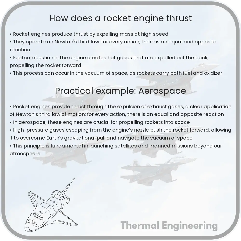
How does a rocket engine thrust

Delve into the workings of rocket engines and the principles of thrust generation using Newton’s laws, fuel types, and the mathematics behind propulsion.

How does a rocket engine thrust

Understanding Rocket Engine Thrust

Rocket engines are fascinating pieces of engineering designed to propel objects through the vacuum of space. But how exactly do these engines create the thrust necessary for launching a rocket out of Earth’s atmosphere or maneuvering it in space? Let’s break down the basic principles of rocket engine operation, using Newton’s laws of motion as our guide.

Newton’s Third Law and Rocket Propulsion

Newtons third law of motion states that for every action, there is an equal and opposite reaction. This principle is fundamental to understanding how rocket engines work. In the simplest terms, a rocket engine expels mass in one direction, and as a reaction, the rocket itself is pushed in the opposite direction.

The Role of Propellant in Rocket Engines

Rocket engines operate by burning a mixture of fuel and an oxidizer, collectively known as propellant. The engine rapidly heats this propellant, converting it into a high-pressure gas. This gas is then directed out of the rocket nozzle at high speed, creating thrust.

The Process of Thrust Generation

  1. Combustion: Inside the combustion chamber, fuel and oxidizer react chemically to form hot, high-pressure gases.
  2. Expansion: These gases expand rapidly and are funneled towards the nozzle, where the area decreases, guiding the gases out at increased speeds.
  3. Exhaust: The gases exit the rocket nozzle at high velocity, pushing against the internal structure of the rocket and creating the forward thrust (as per Newton’s third law).

Mathematics of Rocket Thrust

The thrust (F) generated by a rocket engine can be quantified using the rocket equation, formally known as the Tsiolkovsky rocket equation:

F = m * v + (dm/dt) * ve

  • m: the mass of the rocket
  • v: the velocity of the rocket
  • dm/dt: the rate at which the rocket loses mass, i.e., the rate of fuel consumption
  • ve: the exhaust velocity of the gases expelled from the rocket nozzle

This equation illustrates that the thrust of a rocket is directly dependent on the rate at which the propellant is expended and the velocity at which it is ejected.

Types of Rocket Engines

There are several types of rocket engines, each utilizing different engineering solutions to achieve thrust:

  • Liquid rocket engines: Use liquid propellants. They are complex but allow greater control over the engine’s thrust output.
  • Solid rocket engines: Use solid propellants. They are simpler and generally more reliable, but once ignited, they cannot be throttled or turned off.
  • Hybrid rocket engines: Combine aspects of solid and liquid rocket engines, using solid fuel and a liquid or gaseous oxidizer.

Conclusion

Rocket engines are powerful examples of applying physics and engineering principles to achieve remarkable feats, such as space travel. Understanding these principles not only gives insight into the functionalities of rockets but also highlights the innovations and complexities involved in space exploration technology. By examining the basic mechanics of how rocket engines produce thrust, we gain a better appreciation for the challenges and achievements of aerospace engineering.

How does a cooling tower reduce water temperature

Learn how cooling towers utilize evaporation and heat exchange to reduce water temperature in industrial processes.

How does a cooling tower reduce water temperature

Understanding How a Cooling Tower Reduces Water Temperature

Cooling towers are a vital component in many industrial processes such as power generation, manufacturing, and air conditioning systems. Their primary role is to remove excess heat from a building or facility by lowering the temperature of water heated during industrial processes. Let’s delve into the basic operation of a cooling tower and understand how it effectively reduces water temperature.

The Basic Principle

Cooling towers operate on the principle of heat removal through the process of evaporation and heat exchange. When water is used to absorb heat from industrial processes, it becomes hot and needs to be cooled down for reuse or safe disposal. This is where cooling towers come into play.

Components of a Cooling Tower

  • Water Basin: Collects the cooled water at the bottom of the tower.
  • Fill Material: Increases the surface area for heat exchange.
  • Fans: Help in air circulation within the tower.
  • Water Distribution System: Spreads hot water over the fill material.
  • Drift Eliminators: Reduce water droplets carried away with the air.

Process of Cooling

The operation of a cooling tower starts when hot water from industrial processes is pumped into the tower. This water is then distributed at the top and allowed to flow downward through the fill material. Simultaneously, air is either naturally drawn in or mechanically forced into the tower, moving upward and opposite to the water flow.

The key process here involves two primary types of heat transfer:

  1. Evaporative Cooling: As the hot water cascades down the fill material, some amount of water naturally evaporates due to the exposure to the air flow. This evaporation absorbs significant amounts of heat from the remaining water due to the latent heat of vaporization, effectively cooling it.
  2. Sensible Heat Transfer: The air that enters the tower is cooler than the falling water, and as it rises through the fill, it absorbs some of the water’s heat. This process not only cools down the water but also warms the air which then exits from the top of the tower.

The result is that the water which collects in the basin at the bottom of the cooling tower is significantly cooler. This water can then be recirculated through the system, completing the cycle of cooling.

Efficiency and Types of Cooling Towers

Cooling towers can be categorized primarily into natural draft and mechanical draft, with the latter having further subdivisions such as forced draft and induced draft cooling towers. The efficiency of cooling towers depends on various factors including the type of tower, the wet bulb temperature of the air, the characteristics of the fill material, and the water distribution method.

Mechanical draft cooling towers, which use fans to enhance airflow, are typically more efficient than natural draft towers, especially in climatic conditions not conducive to natural cooling.

Conclusion

Cooling towers are an essential component in managing heat in industrial processes. By understanding the simple yet effective mechanism of evaporative cooling and sensible heat transfer, these towers efficiently manage and reuse water resources, ensuring environmental sustainability and operational efficiency. Whether for industrial plants, power generation, or HVAC systems, cooling towers play a crucial role in maintaining optimal temperatures and system efficiencies.

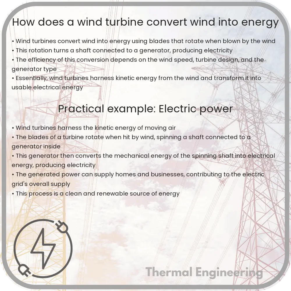
How does a wind turbine convert wind into energy

Learn how wind turbines transform wind into electricity through steps like capturing wind by blades, rotation and torque production, and the role of generators, detailed in accessible language.

How does a wind turbine convert wind into energy

Understanding How Wind Turbines Convert Wind into Energy

Wind turbines are a cornerstone of sustainable energy strategies worldwide, harnessing the natural power of the wind to generate electricity. But how does a seemingly simple breeze transform into energy that powers our homes, businesses, and industries? This article will explain the process in easy-to-understand terms.

The Basics of Wind Energy Conversion

At its core, the operation of a wind turbine involves converting the kinetic energy of wind into mechanical power, which can then be converted into electricity. This process can be broken down into several steps:

  1. Capture of Wind by Blades: As wind strikes the blades of a turbine, they are designed to capture and channel that energy, causing rotation. The blades are shaped and angled like airfoils or wings, which helps them exert a lift force perpendicular to the direction of wind.
  2. Rotation and Torque Production: The rotation of the blades around the rotor generates torque. This mechanical force is the twisting force that we need to generate electricity.
  3. Transmission of Rotational Energy: The rotor’s central shaft is connected to a gearbox within the nacelle (the covering housing at the top of the turbine). This gearbox is designed to increase the rotation speed sufficient for the generator.
  4. Generation of Electricity: This fast rotation is transferred to a generator, where electromagnetic induction occurs. As the shaft rotates, it spins magnets within the generator. The movement of these magnets past coils of wire induces an electrical current, thereby generating electricity.

The Role of the Generator

The generator is the heart of the wind turbine, performing the crucial task of turning mechanical energy into electrical energy. It typically operates on the principle of electromagnetic induction, determined by Faraday’s Law of electromagnetic induction which states that the voltage induced in any circuit is proportional to the rate of change of magnetic flux through the circuit.

In practical terms, this process within the generator translates the mechanical turning motion of the turbine into electrical energy by forcing electrons to move through an external circuit. This flow of electrons is what we use as electricity.

Power Output of Wind Turbines

The amount of electricity a wind turbine can generate depends on several factors:

  • Wind Speed: Higher wind speeds generate more power. The relationship between wind speed and power output is cubic, meaning that even small increases in wind speed result in a significant rise in power output.
  • Turbine Size: Larger turbines with longer blades can catch more wind energy and thus generate more power.
  • Air Density: Denser air contains more air molecules and can transfer more energy than less dense air.

The equation for the power extracted by a wind turbine (P) is expressed as follows:

P = 0.5 * ρ * A * v3

Where:

  • P is the power in watts (W),
  • ρ (rho) is the air density in kilograms per cubic meter (kg/m3),
  • A is the rotor area in square meters (m2), and
  • v is the wind speed in meters per second (m/s).

Conclusion

Wind turbines convert the kinetic energy of wind into usable electrical energy through a sophisticated synergy of aerodynamics, mechanical engineering, and principles of electromagnetic induction. As the world moves toward more sustainable energy systems, understanding and improving the efficiency of technologies like wind turbines is paramount. These marvels of modern engineering not only symbolize human ingenuity but also provide crucial clean energy that helps combat climate change.

By understanding the workflow of wind turbine technology, the potential impact these mechanisms can have on our future energy sustainability becomes vastly transparent, encouraging investment and interest in renewable technologies.

How does a Pelton wheel generate electricity

Learn how the Pelton Wheel turbine, invented by Lester Allan Pelton, efficiently converts water’s kinetic energy into electricity through distinctive design features and operation, ideal for high-head water sources.

How does a Pelton wheel generate electricity

Understanding the Pelton Wheel: Generating Electricity with Water Power

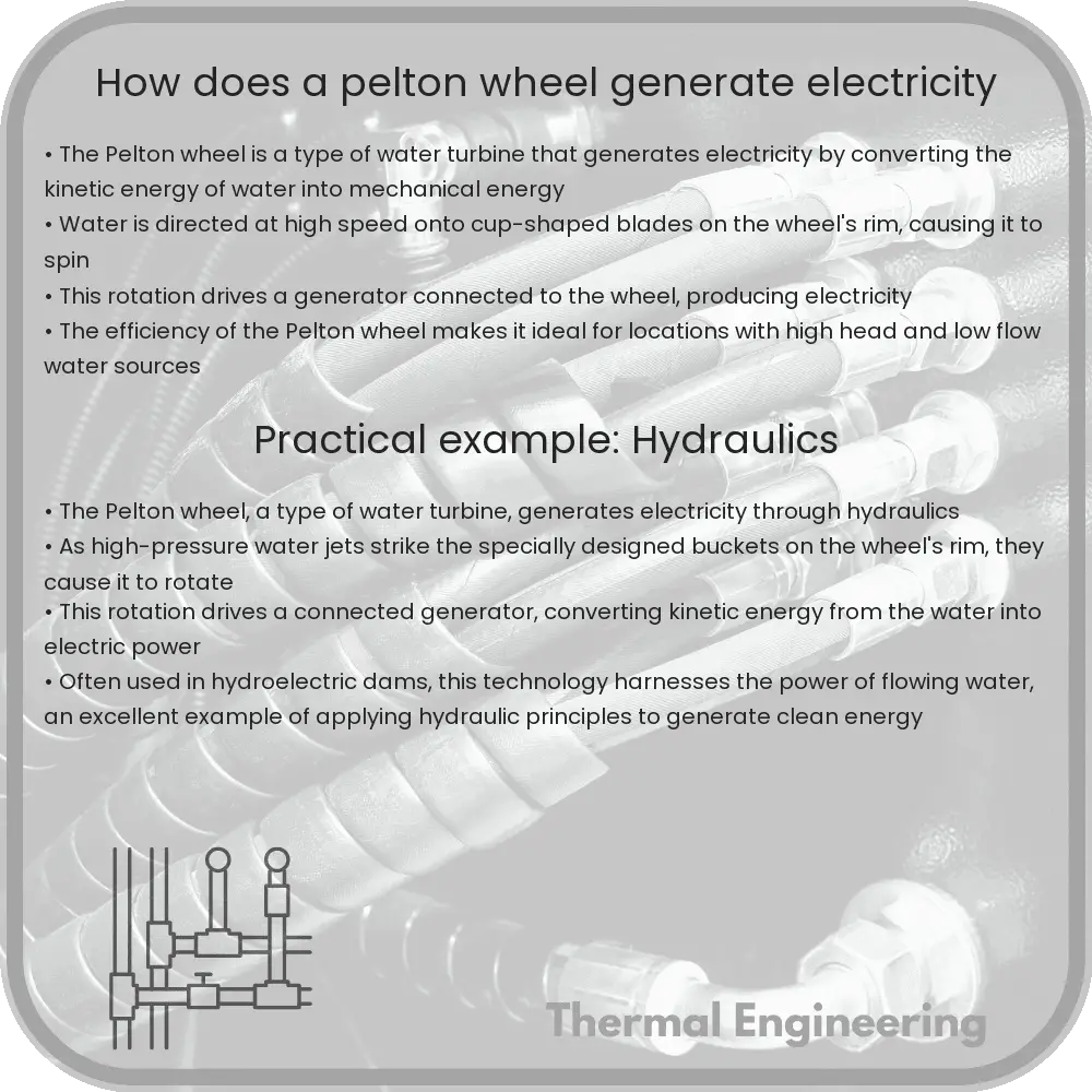
The Pelton wheel is a type of water turbine used to convert the energy of flowing or falling water into mechanical energy, which is then converted into electricity. This conversion is achieved through a highly efficient process that harnesses the kinetic energy of water. The Pelton wheel, named after its inventor Lester Allan Pelton in the 1870s, remains a vital technology in hydroelectric projects, especially suited for high-head water sources.

Design and Function of the Pelton Wheel

The design of the Pelton wheel is characterized by its distinctive bucket-shaped blades, known as buckets, arranged around a circular disc. Each bucket is split down the middle into two symmetrical halves, creating a double-cup shape that captures water jets directed at them. This unique feature allows the Pelton wheel to efficiently manage the water momentum and optimize energy extraction.

How the Pelton Wheel Works

  • Water Supply: Water is led to the turbine through penstocks, which are pipes or channels designed to guide the water from a high elevation reservoir to the turbine. The height from which the water falls, known as the head, is a critical factor in determining the amount of potential energy available in the water.
  • Energy Conversion: As the water reaches the turbine, it passes through a specially designed nozzle that increases its speed and directs the high-speed jets of water at the bucket-shaped blades of the Pelton wheel. When these jets strike the buckets, they impart their kinetic energy to the wheel, causing it to rotate.
  • Power Generation: The rotational movement of the Pelton wheel is transmitted via a connected shaft to an electrical generator. Inside the generator, this mechanical energy is converted into electrical energy through the process of electromagnetic induction.

Mathematical Perspective on Energy Conversion

The efficiency of a Pelton wheel in converting water’s energy into mechanical power can be quantified using basic physical equations:

The kinetic energy of water (KE) that impacts the Pelton wheel can be calculated by the equation:

KE = 0.5 * m * v2

where m is the mass flow rate of the water and v is the velocity of the water jet at the point of impact.

The power (P) generated by the Pelton wheel can be calculated with:

P = KE * η

Here, η (eta) represents the efficiency of the turbine, which can range widely but typically falls between 85% to 90% for well-designed systems.

Advantages of Pelton Wheel Turbines

  • Efficiency: Pelton wheels have the highest efficiency among turbine designs when operating under optimal conditions with high-head and low-flow water sources.
  • Low Maintenance: The simple and robust design of Pelton wheels leads to relatively low maintenance costs and long operational life spans.
  • Flexibility: Pelton wheels can operate effectively across a range of flow conditions, although they are best suited for scenarios involving high head and low volumetric flow rates.

Applications and Importance

Pelton wheel turbines are widely used in small to medium-scale hydroelectric projects around the world. Due to their ability to operate efficiently with high-head conditions and their ease of maintenance, they play a crucial role in sustainable energy generation, particularly in mountainous regions where high-head water sources are abundant.

In summary, the Pelton wheel serves as an important tool in the field of renewable energy, showcasing how simple mechanical principles can harness natural resources like water to produce clean, sustainable power.

How does a thermal camera detect heat

Learn how thermal cameras use infrared technology to visualize heat in various applications like security and medical imaging.

How does a thermal camera detect heat

Understanding How Thermal Cameras Detect Heat

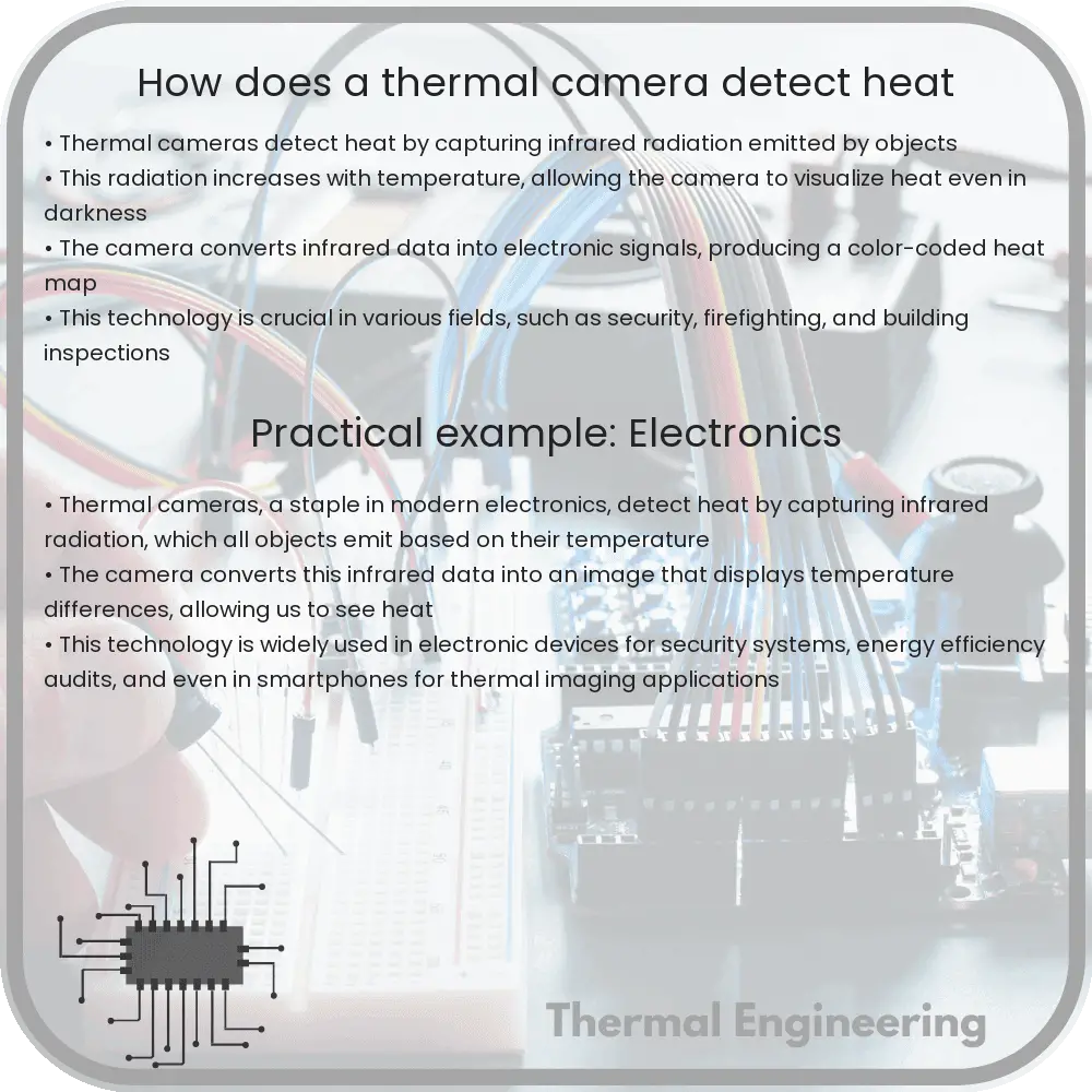
Thermal cameras, also known as infrared cameras, are fascinating devices that allow us to see variations in heat. Unlike standard cameras that capture visible light, thermal cameras are designed to detect and visualize heat emitted by objects. This capability makes them invaluable in numerous applications including security, fire detection, building inspections, and medical imaging. But how do thermal cameras accomplish this?

Basics of Thermal Imaging

Every object emits infrared energy as heat. The amount of this energy depends on its temperature—the warmer an object is, the more infrared energy it emits. Thermal cameras are equipped with a special lens that focuses the infrared light emitted by all of the objects in view. The core of a thermal camera is its infrared detector elements, which are sensitive to different wavelengths of infrared energy.

These detectors are often made from materials such as vanadium oxide or amorphous silicon, which change their electrical resistance when exposed to infrared radiation. When infrared energy from a warm object hits the detector, it changes the temperature of the material. This temperature change alters the material’s resistance, which is then measured and processed to create an electrical signal.

Creating the Thermal Image

The electrical signals from the detector are then sent to the camera’s processor, where they are turned into a digital image. Each pixel in the image corresponds to a point in the detector and represents a temperature value. This temperature data is usually displayed in different colors to indicate different temperatures—cool areas might appear blue, warm areas might be red, and hot areas could be shown in white.

  • Color Palettes: Thermal cameras often have multiple color palettes that can be used to enhance contrast in certain situations, helping the viewer identify temperature differences more easily.
  • Resolution: The resolution of a thermal camera depends on the number of detectors in its array. Higher-resolution cameras can detect smaller temperature variations over longer distances.

Applications of Thermal Cameras

The ability of thermal cameras to see heat makes them incredibly useful in a variety of fields:

  1. Building Inspection: They can reveal heat leaks in buildings and faulty connections in electrical systems.
  2. Medical Diagnostics: Thermal imaging is used in healthcare to monitor blood flow and diagnose inflammation.
  3. Law Enforcement and Security: Thermal cameras improve visibility in dark conditions, providing crucial data not visible to the naked eye.
  4. Firefighting: They can help locate the source of fires and find hotspots that are not visible through smoke.

Conclusion

Thermal cameras are a prime example of how advanced technology can allow us to see beyond the limitations of human vision. By converting infrared radiation into visible images, these cameras provide us with immediate insight into the thermal characteristics of different objects, which can be crucial for both safety and efficiency in many industrial, commercial, and personal applications.

As technology progresses, the applications and capabilities of thermal imaging are likely to expand, opening up even more possibilities for its use in everyday life.