Brayton Cycle – Turbine Engine
In 1872, an American engineer, George Bailey Brayton advanced the study of heat engines by patenting a constant pressure internal combustion engine, initially using vaporized gas but later using liquid fuels such as kerosene. This heat engine is known as “Brayton’s Ready Motor”. It means, the original Brayton engine used a piston compressor and piston expander instead of a gas turbine and gas compressor.
Today, modern gas turbine engines and airbreathing jet engines are also a constant-pressure heat engines, therefore we describe their thermodynamics by the Brayton cycle. In general, the Brayton cycle describes the workings of a constant-pressure heat engine.
It is the one of most common thermodynamic cycles that can be found in gas turbine power plants or in airplanes. In contrast to Carnot cycle, the Brayton cycle does not execute isothermal processes, because these must be performed very slowly. In an ideal Brayton cycle, the system executing the cycle undergoes a series of four processes: two isentropic (reversible adiabatic) processes alternated with two isobaric processes.
Since Carnot’s principle states that no engine can be more efficient than a reversible engine (a Carnot heat engine) operating between the same high temperature and low temperature reservoirs, a gas turbine based on the Brayton cycle must have lower efficiency than the Carnot efficiency.
A large single-cycle gas turbine typically produces for example 300 megawatts of electric power and has 35–40% thermal efficiency. Modern Combined Cycle Gas Turbine (CCGT) plants, in which the thermodynamic cycle of consists of two power plant cycles (e.g. the Brayton cycle and the Rankine cycle), can achieve a thermal efficiency of around 55%.
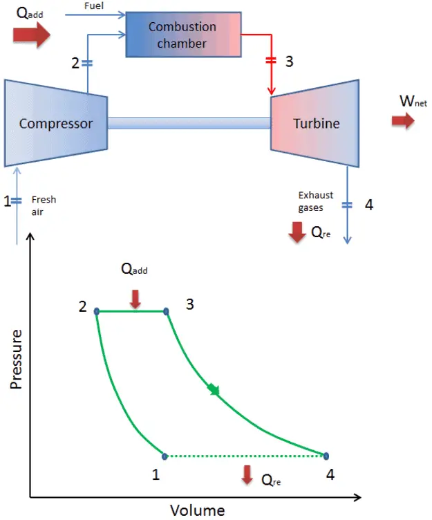
Brayton Cycle – pV, Ts diagram
The Brayton cycle is often plotted on a pressure volume diagram (pV diagram) and on a temperature-entropy diagram (Ts diagram).
When plotted on a pressure volume diagram, the isobaric processes follow the isobaric lines for the gas (the horizontal lines), adiabatic processes move between these horizontal lines and the area bounded by the complete cycle path represents the total work that can be done during one cycle.
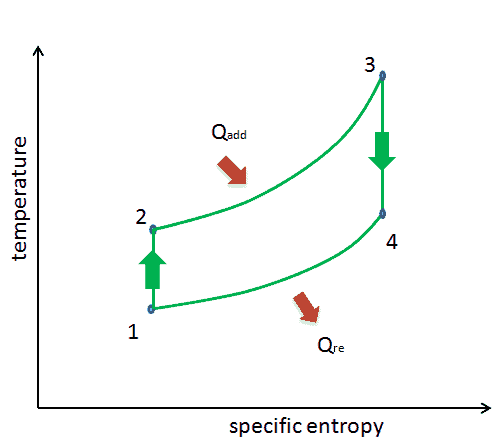
The temperature-entropy diagram (Ts diagram) in which the thermodynamic state is specified by a point on a graph with specific entropy (s) as the horizontal axis and absolute temperature (T) as the vertical axis. Ts diagrams are a useful and common tool, particularly because it helps to visualize the heat transfer during a process. For reversible (ideal) processes, the area under the T-s curve of a process is the heat transferred to the system during that process.
We hope, this article, Brayton Cycle – pV – Ts Diagram, helps you. If so, give us a like in the sidebar. Main purpose of this website is to help the public to learn some interesting and important information about thermal engineering.