How does it work?
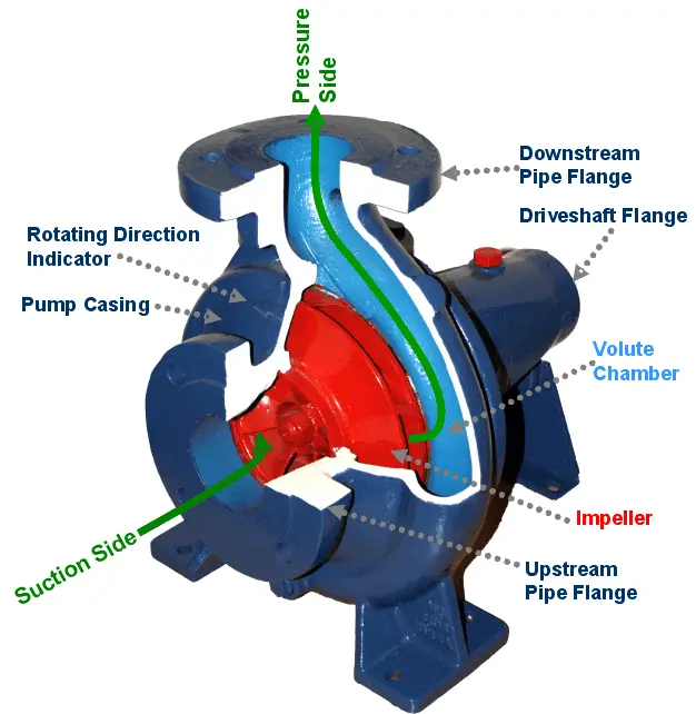
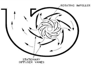
In the volute of the pump fluid enters the pump axially through the eye of the impeller (low pressure area) which rotates at high speed. As the impeller and blades rotate, they transfer momentum to incoming fluid. The fluid accelerates radially outward from the pump chasing and a vacuum is created at the impellers eye that continuously draws more fluid into the pump. As the fluid’s velocity increases its kinetic energy increases. Fluid of high kinetic energy is forced out of the impeller area and enters the volute. In the volute the fluid flows through a continuously increasing cross-sectional area, where the kinetic energy is converted into fluid pressure (according the Bernoulli’s principle).
The impeller blades are usually backward-curved, but there are also radial and forward-curved blade designs. The output pressure slightly changes according to the design used. The blades may be open or closed. Also the diffuser may be fitted with fixed vanes to help guide the flow toward the exit. The energy transferred to the liquid corresponds to the velocity at the edge of the impeller. The faster the impeller revolves or the bigger the impeller is, the higher will the velocity head be.

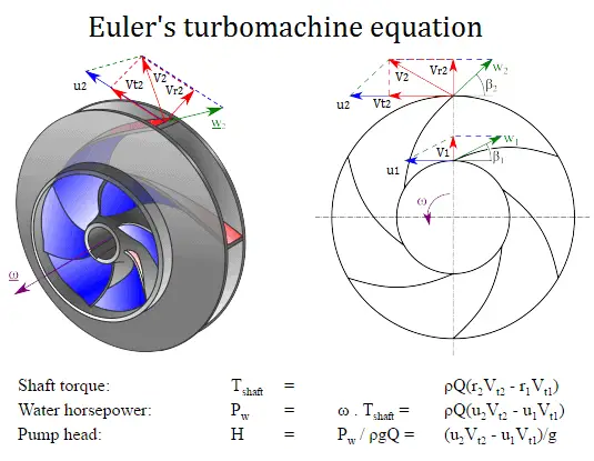
The Euler’s turbomachine equations are:
Shaft torque: Tshaft = ρQ(r2Vt2 – r1Vt1)
Water horsepower: Pw = ω . Tshaft = ρQ(u2Vt2 – u1Vt1)
Pump head: H = Pw / ρgQ = (u2Vt2 – u1Vt1)/g
where
- r1 and r2 are the diameters of the impeller at the inlet and outlet respectively.
- u1 and u2 are the absolute velocities of the impeller (u1 = r1 . ω) at the inlet and outlet respectively.
- Vt1 and Vt2 are the tangential velocities of the flow at the inlet and outlet respectively.
Euler’s turbomachine equations can be used to predict the impact of changing the impeller geometry on the head. It does not matter when we deal with a pump or with a turbine. If torque and angular velocity are of like sign, work is being done on the fluid (a pump or compressor). If torque and angular velocity are of opposite sign work is being extracted from the fluid (a turbine). Thus for the design aspect of turbines and pumps, the Euler equations are extremely useful.
- the design discharge
- water horsepower
- the pump head
of a centrifugal pump. This performance data will be derived from the Euler’s turbomachine equation:
Shaft torque: Tshaft = ρQ(r2Vt2 – r1Vt1)
Water horsepower: Pw = ω . Tshaft = ρQ(u2Vt2 – u1Vt1)
Pump head: H = Pw / ρgQ = (u2Vt2 – u1Vt1)/g
Given are the following data for a centrifugal water pump:
- diameters of the impeller at the inlet and outlet
- r1 = 10 cm
- r2 = 20 cm
- Speed = 1500 rpm (revolutions per minute)
- the blade angle at inlet β1 = 30°
- the blade angle at outlet β2 = 20°
- assume that the blade widths at inlet and outlet are: b1 = b2 = 4 cm.
Solution:
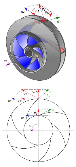
First, we have to calculate the radial velocity of the flow at the outlet. From the velocity diagram the radial velocity is equal to (we assume that the flow enters exactly normal to the impeller, so tangential component of velocity is zero):
Vr1 = u1 tan 30° = ω r1 tan 30° = 2π x (1500/60) x 0.1 x tan 30° = 9.1 m/s
Radial component of flow velocity determines how much the volume flow rate is entering the impeller. So when we know Vr1 at inlet, we can determine the discharge of this pump according to following equation. Here b1 means the blade width of the impeller at inlet.
Q = 2π.r1.b1.Vr1 = 2π x 0.1 x 0.04 x 9.1 = 0.229 m3/s
In order to calculate the water horsepower (Pw) required, we have to determine the outlet tangential flow velocity Vt2, because it has been assumed that the inlet tangential velocity Vt1 is equal to zero.
The outlet radial flow velocity follows from conservation of Q:
Q = 2π.r2.b2.Vr2 ⇒ Vr2 = Q / 2π.r2.b2 = 0.229 / (2π x 0.2 x 0.04) = 4.56 m/s
From the figure (velocity triangle) outlet blade angle, β2, can be easily represented as follows.
cot β2 = (u2 – Vt2) / Vr2
and therefore the outlet tangential flow velocity Vt2 is:
Vt2 = u2 – Vr2 . cot 20° = ω r2 – Vr2 . cot 20° = 2π x 1500/60 x 0.2 – 4.56 x 2.75 = 31.4 – 12.5 = 18.9 m/s.
The water horsepower required is then:
Pw = ρ Q u2 Vt2 = 1000 [kg/m3] x 0.229 [m3/s] x 31.4 [m/s] x 18.9 [m/s] = 135900 W = 135.6 kW
and the pump head is:
H ≈ Pw / (ρ g Q) = 135900 / (1000 x 9.81 x 0.229) = 60.5 m
Main Parts of a Centrifugal Pump
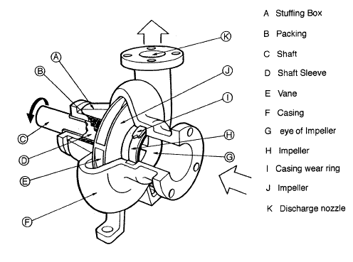
The wet end of the pump includes those parts that determine the hydraulic performance of pump. The two primary wet ends are the impeller and casing. In some cases the first radial bearing can be water lubricated. In this case also bearing can belongs to wet ends.
The mechanical end includes those parts that support the impeller within the casing. The mechanical end of the pump includes the pump shaft, sealing, bearings and shaft sleeve.
These components are designed to perform specific tasks:
 Impeller. Impeller is a rotor used to increase the kinetic energy of the flow.
- Casing (Volute). The casing contains the liquid and acts as a pressure containment vessel that directs the flow of liquid in and out of the centrifugal pump. The volute is a curved funnel that increases in area as it approaches the discharge port. The volute of a centrifugal pump is the casing that receives the fluid being pumped by the impeller, slowing down the fluid’s rate of flow. Therefore, according to Bernoulli’s principle, the volute converts kinetic energy into pressure by reducing speed while increasing pressure. Some centrifugal pumps contain diffusers. A diffuser is a set of stationary vanes that surround the impeller. The diffuser directs the flow, allows a more gradual expansion and therefore increases the efficiency of the centrifugal pump.
- Shaft (Rotor). The impeller is mounted on a shaft. Shaft is a mechanical component for transmitting torque from the motor to the impeller.
- Shaft sealing. Centrifugal pumps are provided with packing rings or mechanical seal which helps prevent the leakage of the pumped liquid.
- Bearings. Bearings constrain relative motion of the shaft (rotor) and reduce friction between the rotating shaft and the stator. There are at least 5 common types of bearing, each of which operates on different principles:
- Plain bearing
- Rolling-element bearing
- Jewel bearing
- Fluid bearing
- Magnetic bearing
We hope, this article, How does centrifugal pump work, helps you. If so, give us a like in the sidebar. Main purpose of this website is to help the public to learn some interesting and important information about thermal engineering.