Types of Steam Turbines
Steam turbines may be classified into different categories depending on their construction, working pressures, size and many other parameters. But there are two basic types of steam turbines:
- impulse turbines
- reaction turbines.
The main distinction is the manner in which the steam is expanded as it passes through the turbine.
Impulse Turbine and Reaction Turbine
Steam turbine types based on blade geometry and energy conversion process are impulse turbine and reaction turbine.
Impulse Turbine
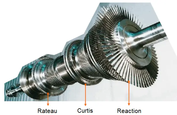
 The impulse turbine is composed of moving blades alternating with fixed nozzles. In the impulse turbine, the steam is expanded in fixed nozzles and remains at constant pressure when passing over the blades. Curtis turbine, Rateau turbine, or Brown-Curtis turbine are impulse type turbines. The original steam turbine, the De Laval, was an impulse turbine having a single-blade wheel.
The entire pressure drop of steam take place in stationary nozzles only. Though the theoretical impulse blades have zero pressure drop in the moving blades, practically, for the flow to take place across the moving blades, there must be a small pressure drop across the moving blades also.
In impulse turbines, the steam expands through the nozzle, where most of the pressure potential energy is converted to kinetic energy. The high-velocity steam from fixed nozzles impacts the blades, changes its direction, which in turn applies a force. The resulting impulse drives the blades forward, causing the rotor to turn. The main feature of these turbines is that the pressure drop per single stage can be quite large, allowing for large blades and a smaller number of stages. Except for low-power applications, turbine blades are arranged in multiple stages in series, called compounding, which greatly improves efficiency at low speeds.
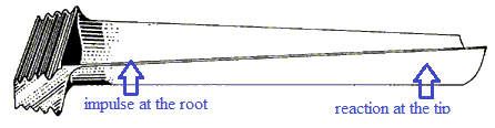
Modern steam turbines frequently employ both reaction and impulse in the same unit, typically varying the degree of reaction and impulse from the blade root to its periphery. The rotor blades are usually designed like an impulse blade at the rot and like a reaction blade at the tip.
Since the Curtis stages reduce significantly the pressure and temperature of the fluid to a moderate level with a high proportion of work per stage. An usual arrangement is to provide on the high pressure side one or more Curtis stages, followed by Rateau or reaction staging. In general, when friction is taken into account reaction stages the reaction stage is found to be the most efficient, followed by Rateau and Curtis in that order. Frictional losses are significant for Curtis stages, since these are proportional to steam velocity squared. The reason that frictional losses are less significant in the reaction stage lies in the fact that the steam expands continuously and therefore flow velocities are lower.
A compounded steam turbine has multiple stages i.e. it has more than one set of nozzles and rotors, in series, keyed to the shaft or fixed to the casing, so that either the steam pressure or the jet velocity is absorbed by the turbine in number of stages. For example, large HP Turbine used in nuclear power plants can be double-flow reaction turbine with about 10 stages with shrouded blades. Large LP turbines used in nuclear power plants are usually double-flow reaction turbines with about 5-8 stages (with shrouded blades and with free-standing blades of last 3 stages).
In an impulse steam turbine compounding can be achieved in the following three ways:
- pressure compounding
- velocity compounding
- pressure-velocity compounding
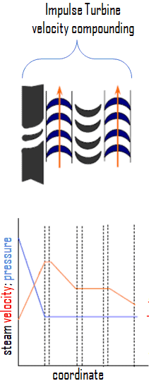
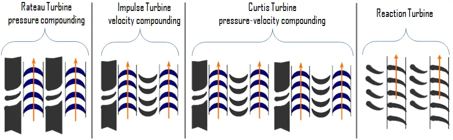
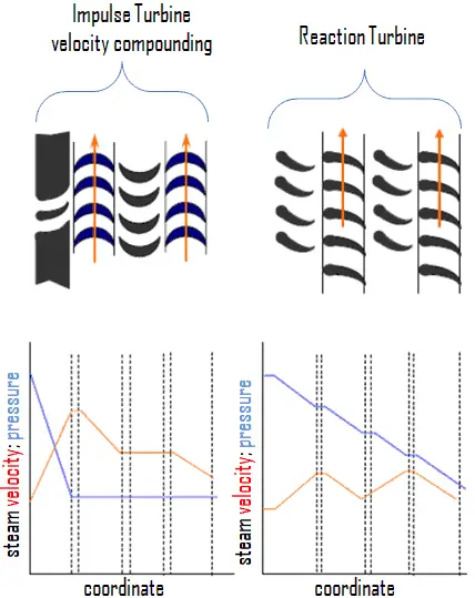
A velocity-compounded impulse stage consist of a row of fixed nozzles followed by two or more rows of moving blades and fixed blades (without expansion). This divides the velocity drop across the stage into several smaller drops. In this type, the total pressure drop (expansion) of the steam take place only in the first nozzle ring. This produces very high velocity steam, which flows through multiple stages of fixed and moving blades. At each stage, only a portion of the high velocity is absorbed, the remainder is exhausted on to the next ring of fixed blades. The function of the fixed blades is to redirect the steam (without appreciably altering the velocity) leaving from the first ring of moving blades to the second ring of moving blades. The jet then passes on to the next ring of moving blades, the process repeating itself until practically all the velocity of the jet has been absorbed.
This method of velocity compounding is used to solve the problem of single stage impulse turbine for use of high pressure steam (i.e. required velocity of the turbine), but they are less efficient due to high friction losses.
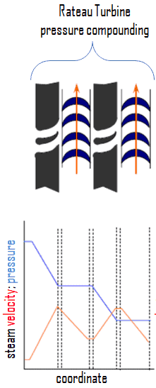
A pressure-compounded impulse stage is a row of fixed nozzles followed by a row of moving blades, with multiple stages for compounding. In this type, the total pressure drop of the steam does not take place in the first nozzle ring, but is divided up between all the nozzle rings. The effect of absorbing the pressure drop in stages is to reduce the velocity of the steam entering the moving blades. The steam from the boiler is passed through the first nozzle ring in which it is only partially expanded. It then passes over the first moving blade ring where nearly all of its velocity (momentum) is absorbed. From this ring it exhausts into the next nozzle ring and is again partially expanded. This method of pressure compounding is used in Rateau and Zoelly turbines, but such turbines are bigger and bulkier in size.
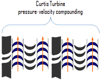
Impulse stages may be either pressure-compounded, velocity-compounded, or pressure-velocity compounded. The pressure-velocity compounding is a combination of the above two types of compounding. In fact, a series of velocity-compounded impulse stages is called a pressure-velocity compounded turbine. Each stage consists of rings of fixed and moving blades. Each set of rings of moving blades is separated by a single ring of fixed nozzles. In each stage there is one ring of fixed nozzles and 3-4 rings of moving blades (with fixed blades between them). Each stage acts as a velocity compounded impulse turbine.
The steam coming from the steam generator is passed to the first ring of fixed nozzles, where it gets partially expanded. The pressure partially decreases and the velocity rises correspondingly. It then passes over the 3-4 rings of moving blades (with fixed blades between them) where nearly all of its velocity is absorbed. From the last ring of the stage it exhausts into the next nozzle ring and is again partially expanded.
This has the advantage of allowing a bigger pressure drop in each stage and, consequently, less stages are necessary, resulting in a shorter turbine for a given pressure drop. It may be seen that the pressure is constant during each stage; the turbine is, therefore, an impulse turbine. The method of pressure-velocity compounding is used in the Curtis turbine.
Reaction Turbine – Parsons Turbine
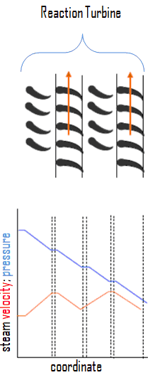
In reaction turbines, the steam expands through the fixed nozzle , where the pressure potential energy is converted to kinetic energy. The high-velocity steam from fixed nozzles impacts the blades (nozzles), changes its direction and undergo further expansion. The change in its direction and the steam acceleration applies a force. The resulting impulse drives the blades forward, causing the rotor to turn. Ther is no net change in steam velocity across the stage but with a decrease in both pressure and temperature, reflecting the work performed in the driving of the rotor. In this type of turbine the pressure drops take place in a number of stages, because the pressure drop in a single stage is limited.
The main feature of this type of turbine is that in contrast to the impulse turbine, the pressure drop per stage is lower, so the blades become smaller and the number of stages increases. On the other hand, reaction turbines are usually more efficient, i.e. they have higher “isentropic turbine efficiency”. The reaction turbine was invented by Sir Charles Parsons and is known as the Parsons turbine.
In the case of steam turbines, such as would be used for electricity generation, a reaction turbine would require approximately double the number of blade rows as an impulse turbine, for the same degree of thermal energy conversion. Whilst this makes the reaction turbine much longer and heavier, the overall efficiency of a reaction turbine is slightly higher than the equivalent impulse turbine for the same thermal energy conversion.
Modern steam turbines frequently employ both reaction and impulse in the same unit, typically varying the degree of reaction and impulse from the blade root to its periphery. The rotor blades are usually designed like an impulse blade at the rot and like a reaction blade at the tip.
Classification of Turbines – steam supply and exhaust conditions
Steam turbines may be classified into different categories depending on their purpose and working pressures. The industrial usage of a turbine influences the initial and final conditions of steam. For any steam turbine to operate, a pressure difference must exist between the steam supply and the exhaust.
This classification includes:
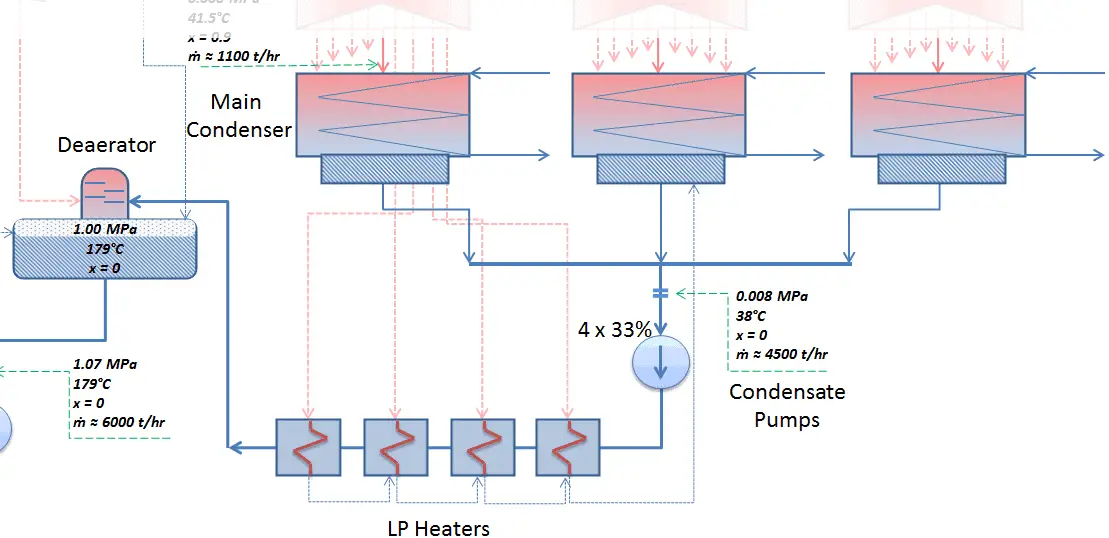
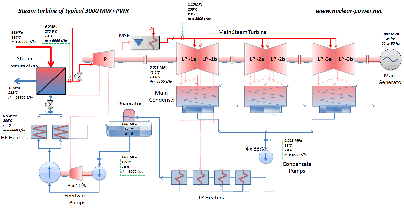
Condensing steam turbines are most commonly found in thermal power plants. In a condensing steam turbine, the maximum amount of energy is extracted from the steam, because there is very high enthalpy difference between the initial (e.g. 6MPa; 275°C; x = 1) and final (e.g. 0.008MPa; 41.5°C; x = 0.9) conditions of steam. This is achieved by passing the exhaust steam into a condenser (called a surface condenser), which condenses the exhaust steam from the low-pressure stages of the main turbine (decreases the temperature and pressure of exhausted steam). The exhausted steam is condensed by passing over tubes containing water from the cooling system.
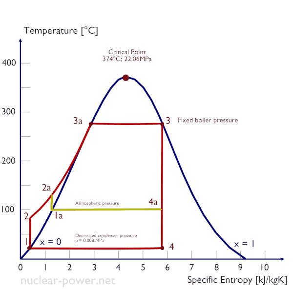
The goal of maintaining the lowest practical turbine exhaust pressure is a primary reason for including the condenser in a thermal power plant. The condenser provides a vacuum that maximizes the energy extracted from the steam, resulting in a significant increase in net work and thermal efficiency. But also this parameter (condenser pressure) has its engineering limits:
- Decreasing the turbine exhaust pressure decreases the vapor quality (or dryness fraction). At some point the expansion must be ended to avoid damages that could be caused to blades of steam turbine by low quality steam.
- Decreasing the turbine exhaust pressure significantly increases the specific volume of exhausted steam, which requires huge blades in last rows of low-pressure stage of the steam turbine.
In a typical condensing steam turbine, the exhausted steam condenses in the condenser and it is at a pressure well below atmospheric (absolute pressure of 0.008 MPa, which corresponds to 41.5°C). This steam is in a partially condensed state (point F), typically of a quality near 90%. Note that, the pressure inside the condenser is also dependent on the ambient atmospheric conditions:
- air temperature, pressure and humidity in case of cooling into the atmosphere
- water temperature and the flow rate in case of cooling into a river or sea
An increase in the ambient temperature causes a proportional increase in pressure of exhausted steam (ΔT = 14°C is usually a constant) hence the thermal efficiency of the power conversion system decreases. In other words, the electrical output of a power plant may vary with ambient conditions, while the thermal power remains constant.
The pressure inside condenser is given by the ambient air temperature (i.e. temperature of water in the cooling system) and by steam ejectors or vacuum pumps, which pull the gases (non-condensibles) from the surface condenser and eject them to the atmosphere.
The lowest feasible condenser pressure is the saturation pressure corresponding to the ambient temperature (e.g. absolute pressure of 0.008 MPa, which corresponds to 41.5°C). Note that, there is always a temperature difference between (around ΔT = 14°C) the condenser temperature and the ambient temperature, which originates from finite size and efficiency of condensers.
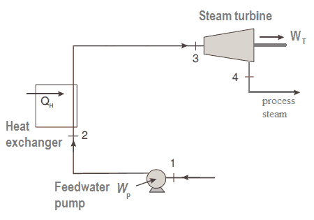
Back-pressure steam turbines or non-condensing turbines are most widely used for process steam applications. Steam is a principle energy source for many industrial processes. The popularity of process steam as an energy source stems from its many advantages, which include:
- high heat capacity,
- transportability
- low toxicity
The process steam can be produced by back-pressure steam turbines, which also generates mechanical work (or electrical energy). Back-pressure turbines expand the live steam supplied by the boiler to the pressure at which the steam is required for the process. The exhaust pressure is controlled by a regulating valve to suit the needs of the process steam pressure. Back-pressure turbines are commonly found at refineries, district heating units, pulp and paper plants, and desalination facilities where large amounts of low pressure process steam are needed. The electric power generated by the back-pressure turbine is directly proportional to the amount of process steam required.

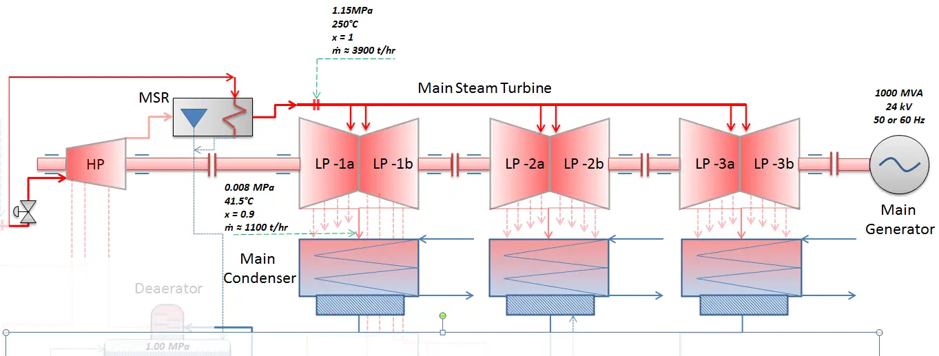
Reheat turbines are also used almost exclusively in thermal power plants. All turbines, that have high-pressure turbine and low-pressure turbines use a steam reheat between these stages. Reheat allows to deliver more of the heat at a temperature close to the peak of the cycle (i.e. thermal efficiency increases). This requires the addition of another type of heat exchanger called a reheater. The use of the reheater involves splitting the turbine, i.e. use of a multistage turbine with a reheater. It was observed that more than two stages of reheating are unnecessary, since the next stage increases the cycle efficiency only half as much as the preceding stage.
High pressure and low pressure stages of the turbine are usually on the same shaft to drive a common generator, but they have separate cases. With a reheater, the flow is extracted after a partial expansion (point D), run back through the heat exchanger to heat it back up to the peak temperature (point E), and then passed to the low-pressure turbine. The expansion is then completed in the low-pressure turbine from point E to point F.
The steam must be reheated or superheated in order to avoid damages that could be caused to blades of steam turbine by low quality steam. High content of water droplets can cause the rapid impingement and erosion of the blades which occurs when condensed water is blasted onto the blades. To prevent this, condensate drains are installed in the steam piping leading to the turbine. The reheater heats the steam (point D) and then the steam is directed to the low-pressure stage of steam turbine, where expands (point E to F). The exhausted steam is at a pressure well below atmospheric, and, as can be seen from the picture, the steam is in a partially condensed state (point F), typically of a quality near 90%, but it is much higher vapor quality, than that it would be without reheat. Accordingly, superheating also tends to alleviate the problem of low vapor quality at the turbine exhaust.
Almost all large steam turbines use the heat regeneration (i.e. they are extraction turbines), since it reduces the amount of fuel that must be added in the boiler. The reduction in the heat added can be done by transferring heat (partially expanded steam) from certain sections of the steam turbine, which is normally well above the ambient temperature, to the feedwater. Note that, most of energy contained in the steam is in the form of latent heat of vaporization. Extraction flows may be controlled with a valve, or left uncontrolled.
For example, most of nuclear power plants operates a single-shaft turbine-generator that consists of one multi-stage HP turbine with 3 or 4 self-regulating extraction lines and three parallel multi-stage LP turbines with 3 or 4 self-regulating extraction lines.
The high pressure feedwater heaters are usually heated by extraction steam from the high pressure turbine, HP, whereas the low-pressure feedwater heaters are usually heated by extraction steam from the low pressure turbine, LP. Both are usually self-regulating. It means that the greater the flow of feedwater the greater the rate of heat absorption from the steam and the greater the flow of extraction steam.
We hope, this article, Type of Steam Turbines, helps you. If so, give us a like in the sidebar. Main purpose of this website is to help the public to learn some interesting and important information about thermal engineering.