Vapor-compression Cycle – Refrigeration Cycle
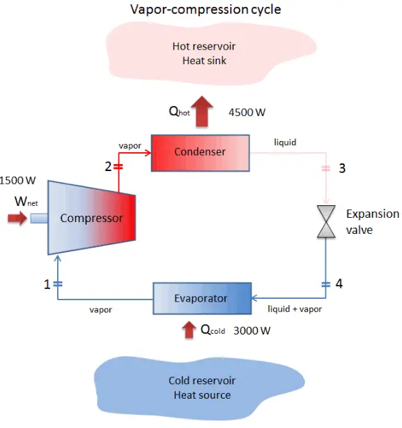
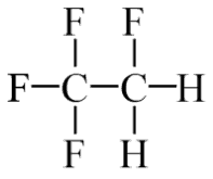
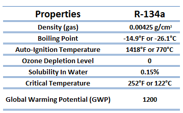
The vapor-compression uses a circulating liquid refrigerant as the medium (usually R134a) which absorbs and removes heat from the space to be cooled and subsequently rejects that heat elsewhere. The figure depicts a typical, single-stage vapor-compression system. The typical vapor-compression system consist of four components:
- Compressor
- Condenser
- Expansion valve (also called a throttle valve)
- Evaporator
In an ideal vapor-compression cycle, the system executing the cycle undergoes a series of four processes: one isentropic (reversible adiabatic) process, one throttling process alternated with two isobaric processes:
- Isentropic compression (compression in the piston compressor) – A circulating refrigerant such as R134a enters a compressor as low-pressure vapor at or slightly below the temperature of the refrigerator interior. The gaseous medium is compressed adiabatically from state 1 to state 2 by piston compressor (or by centrifugal pumps) to a relatively high pressure and temperature. The surroundings do work on the gas, increasing its internal energy (temperature) and compressing it (increasing its pressure). On the other hand the entropy remains unchanged. The work required for the compressor is given by WC = H2 – H1.
- Isobaric heat rejection (in a condenser) – The superheated vapor travels under pressure through coils or tubes that make up the condenser. In this phase the refrigerant passes through the condenser, where the refrigerant condenses and there is heat transfer from the refrigerant to the cooler surroundings. The net heat rejected is given by Qre = H3 – H2. As the refrigerant leaves the condenser, it is still under pressure but is now only slightly above room temperature.
- Isenthalpic process (expansion in an expansion valve) – The refrigerant at state 3 enters the expansion valve and expands to the evaporator pressure. This process is usually modeled as a throttling process for which enthalpy remains constant. H4 = H3. The sudden decrease in pressure results in explosive-like flash evaporation of a portion (typically about half) of the liquid. The latent heat absorbed by this flash evaporation is drawn mostly from adjacent still-liquid refrigerant, a phenomenon known as auto-refrigeration.
- Isobaric heat addition (in an evaporator) – The cold and partially vaporized refrigerant continues through the coils or tubes of the evaporator unit. In this phase (between state 4 and state 1) there is a constant-pressure heat transfer to the liquid medium from an external source, since the chamber is open to flow in and out. As the refrigerant passes through the evaporator, heat transfer from the refrigerated space results in the vaporization of the refrigerant. The net heat added is given by Qadd = H1 – H4
During a vapor-compression cycle, work is done on the fluid by the pumps between states 1 and 2 (isentropic compression). There is no work is done by the fluid since between stages 3 and 4 the process is isenthalpic. The working fluid in a vapor-compression cycle follows a closed loop and is reused constantly.
Coefficient of Performance – Heat Pump, Refrigerator, Air Conditioner
In general, the thermal efficiency, ηth, of any heat engine as the ratio of the work it does, W, to the heat input at the high temperature, QH.
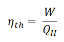
The thermal efficiency, ηth, represents the fraction of heat, QH, that is converted to work.
But in heat pumps and refrigerators, the work is not an output. For a refrigeration or heat pumps, thermal efficiency indicates the extent to which the energy added by work is converted to net heat output. From an economic point of view, the best refrigeration cycle is one that removes the greatest amount of heat from the inside of the refrigerator (cold reservoir) for the least expenditure of mechanical work or electric energy. The relevant ratio is therefore the larger this ratio, the better the refrigerator. We call this ratio the coefficient of performance, denoted by COP.
The coefficient of performance, COP, is defined also for heat pumps, but at this point we follow the net heat added to the hot reservoir. The COP usually exceeds 1, especially in heat pumps, because, instead of just converting work to heat, it pumps additional heat from a heat source to where the heat is required.
In general, COP is highly dependent on operating conditions, especially absolute temperature and relative temperature between heat sink and system.
Coefficient of Performance – Refrigerator, Air Conditioner
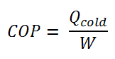
The coefficient of performance, COP, of a refrigerator is defined as the heat removed from the cold reservoir Qcold, (i.e. inside a refrigerator) divided by the work W done to remove the heat (i.e. the work done by the compressor).
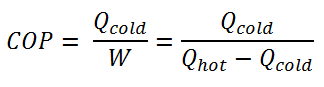
As can be seen, the better (more efficient) the refrigerator is when more heat Qcold can be removed from the inside of the refrigerator for a given amount of work. Since the first law of thermodynamics must be valid also in this case (Qcold + W = Qhot), we can rewrite the above equation:
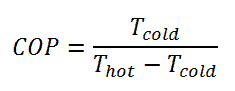
For an ideal refrigerator (without losses and irreversibilities) can be derived that:
These formulas are applied also for an air conditioner, which works very much like a refrigerator.
On the other hand, the COP for heating and cooling are different.
Coefficient of Performance – Heat Pump
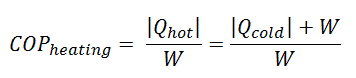
For heating, the COP is the ratio of the heat added to the system (hot reservoir). Using the first law of thermodynamics define COP also as the heat removed from the cold reservoir plus the input work to the input work.
For an ideal heat pump (without losses and irreversibilities) can be derived that:
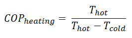
Note that, these equations must use an absolute temperature scale (Tcold, Thot) and it is only a theoretical maximum efficiency. According to the above formula, the maximum achievable COP for Thot = 35 °C (308 K) and Tcold = 0 °C (273 K) would be 8.8. But in reality the best systems are around 4.5.
As can be seen, the COP of a heat pump system can be improved by reducing the temperature difference (Thot – Tcold). Therefore, reducing the output temperature (Thot) is very efficient, but requires very efficient heat transfer from heat pump system to surroundings (i.e. use of piped floor). An increase in the input temperature (Tcold) means, for example, an oversized ground source of heat.
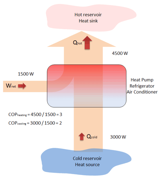
Example – Heat Pump – Heating and Air Conditioning
A reversible heat pump has a coefficient of performance, COP = 3.0, when operated in the heating mode. Its compressor consumes 1500 W of electric energy.
- Calculate the amount of heat (Qhot) the heat pump can add to a room?
- If the heat pump were turned to the cooling mode (i.e. to act as an air conditioner in the summer), what would you expect its coefficient of performance to be? Assume all else stays the same and neglect all other losses.
Solution:
From the COP, which is defined as:
the amount of heat the heat pump can add to a room is equal to:
Qhot = COPheating x W = 3 x 1500 = 4500 W or 4500 J/s
In case of the cooling mode, the heat pump (air conditioner) with 1500 W motor can take heat Qcold from inside the house and then dump Qhot = 4500 W to the hot outside. Using the first law of thermodynamics, which states:
Qcold + W = Qhot,
we obtain the heat, Qcold = 3000 W. From the definition: COPcooling = 3000/1500 = 2.
Note that, in this example we have many assumptions. For example, we assumed that the temperature difference (Thot – Tcold) is the same for both modes. But we have swapped reservoirs, without any impact on COP. It is only an illustrative example.
We hope, this article, Vapor-compression Cycle – Refrigeration Cycle, helps you. If so, give us a like in the sidebar. Main purpose of this website is to help the public to learn some interesting and important information about thermal engineering.