Facebook Instagram Youtube Twitter

Basics of Thermal Radiation in Heat Transfer

Learn about thermal radiation, a key mode of heat transfer that involves energy emitted by bodies due to their temperature and travels as electromagnetic waves.

Basics of Thermal Radiation in Heat Transfer

Understanding Thermal Radiation in Heat Transfer

Heat transfer is a fundamental concept in both engineering and physics, describing the process by which thermal energy is exchanged between physical systems. One of the three primary modes of heat transfer is thermal radiation, which unlike conduction and convection, does not require a medium to propagate. This article explores the basics of thermal radiation, explaining its principles, characteristics, and real-world applications.

What is Thermal Radiation?

Thermal radiation is energy emitted by a body due to its temperature. It is a form of electromagnetic radiation, which means it can travel through the vacuum of space. The intensity and wavelength of the radiation depend on the temperature of the emitting body. All objects above absolute zero (0 K) emit thermal radiation, making this a ubiquitous phenomenon in both nature and engineered systems.

The Laws Governing Thermal Radiation

  • Planck’s Law: This law describes the spectrum of radiation emitted by a body at a definite temperature. Planck’s Law helps in determining the distribution of electromagnetic radiation at different wavelengths.
  • Stefan-Boltzmann Law: It states that the total energy radiated per unit surface area of a black body in unit time (j*) is directly proportional to the fourth power of the black body’s temperature (T). Mathematically, it is expressed as:

    j* = σT4

    where σ (sigma) is the Stefan-Boltzmann constant, approximately equal to 5.67 x 10⁻⁸ W/m2K4.

  • Wien’s Displacement Law: This law indicates that the wavelength at which the intensity of radiation is maximum decreases as the temperature increases. It is useful for determining the peak wavelength of emitted radiation, giving an insight into the energy characteristics of the radiation.

Factors Affecting Thermal Radiation

  • Temperature: Higher temperatures result in increased radiation intensity. As per the Stefan-Boltzmann Law, a small increase in the body’s temperature will produce a disproportionately large increase in the radiation it emits.
  • Surface properties: Surfaces with different emissivities emit radiation differently. A perfect black body, which has an emissivity of 1, emits the maximum amount of radiation possible at a given temperature and is purely theoretical. Real-world materials have emissivities less than 1, affecting their thermal radiation properties.

Applications of Thermal Radiation

Thermal radiation principles find applications across various fields, including:

  1. Astronomy: Scientists study the thermal radiation emitted by celestial bodies to determine their temperature and composition.
  2. Thermal imaging: This technology uses cameras that detect radiation in the infrared range of the electromagnetic spectrum, making it possible to see areas of heat whether in darkness or obscured by smoke.
  3. Building design: Understanding thermal radiation helps in designing buildings that optimize energy usage for heating and cooling. Materials are chosen based on how well they absorb or emit radiation.
  4. Solar panels: Solar technology uses radiation from the sun to generate electricity, efficiently converting solar radiation into usable energy.

Conclusion

Thermal radiation plays an essential role in the study and application of heat transfer processes in various engineering and scientific contexts. By understanding the fundamental principles that govern this form of radiation, professionals can design more efficient systems and improve existing technologies. With its wide range of applications, from industrial manufacturing to environmental control, thermal radiation remains a critical area of study within both engineering and physics.


What Is Specific Heat Capacity?

Learn the definition and applications of specific heat capacity, a key concept in thermodynamics that measures how different substances react to heat.

What Is Specific Heat Capacity?

What Is Specific Heat Capacity?

Specific heat capacity, often simply called specific heat, is a fundamental physical property of any substance. It represents the amount of heat energy required to raise the temperature of a unit mass of a substance by one degree Celsius (or one Kelvin). Specific heat capacity is a crucial concept in both thermodynamics and engineering, influencing how materials respond to thermal energy in processes ranging from industrial manufacturing to climate science.

Understanding the Basics

The specific heat capacity of a material can be thought of as a measure of its thermal inertia. A material with a high specific heat capacity can absorb a lot of heat without experiencing a significant increase in temperature. This property affects everything from the cooling of electronic components to the heating of buildings.

The formula used to calculate the amount of heat absorbed or released by a substance as its temperature changes is given by:

Q = mcΔT

where:

  • Q is the heat added (in joules, J)
  • m is the mass of the substance (in kilograms, kg)
  • c is the specific heat capacity (in joules per kilogram per degree Celsius, J/kg°C)
  • ΔT is the change in temperature (in degrees Celsius, °C)

Variations Among Different Substances

Different materials have different specific heat capacities, which can vary significantly. For instance, water has a remarkably high specific heat capacity of approximately 4182 J/kg°C, making it excellent for applications where heat absorption or dissipation is needed, such as in cooling systems or climate control systems.

Metals typically have lower specific heat capacities, which means they heat up and cool down more quickly than water. For example, the specific heat capacity of copper is around 385 J/kg°C, whereas aluminum is approximately 900 J/kg°C.

Practical Applications

The concept of specific heat capacity finds utility in a wide range of engineering applications:

  • Climate Engineering: Understanding and modeling the specific heat capacities of different components of the Earth’s system (like oceans and atmosphere) is essential for predicting and managing climate change.
  • Mechanical Engineering: In designing engines and other mechanical systems, engineers must take into account the specific heat capacities of materials to ensure proper thermal management.
  • Culinary Technology: Specific heat capacity is key in food science, affecting how different foods are cooked and how they respond to temperature changes.

Conclusion

The specific heat capacity is an invaluable property that helps define how substances interact with heat. Its impact on various engineering and scientific disciplines cannot be overstated, influencing everything from the design of small appliances to large-scale environmental systems. By better understanding specific heat capacity, engineers and scientists can develop more efficient, effective, and sustainable technologies and solutions.

In everyday terms, the specific heat capacity is why certain materials feel cooler to the touch than others at the same temperature, and it plays a critical role in our understanding of not just engineering systems but also natural phenomena.

Thermal energy conversion systems

Comprehensive guide on thermal energy conversion systems, covering key types, components, and applications for efficient power generation.

Thermal energy conversion systems

Understanding Thermal Energy Conversion Systems

Thermal energy conversion systems are crucial for harnessing energy from heat sources and converting it into usable power, typically electricity. This concept is pivotal in various applications, ranging from large-scale power generation to small-scale applications like automotive engines. This article will explore the basic principles of thermal energy conversion systems, including their types, components, and applications.

Types of Thermal Energy Conversion Systems

There are several types of thermal energy conversion systems, each differing by the source of heat and the method of conversion:

  • Steam Turbines: Widely used in power generation, steam turbines convert high-pressure steam, produced from boilers or heat recovery steam generators, into mechanical energy that drives generators to produce electricity.
  • Internal Combustion Engines: Common in automotive applications, these engines burn fuel to create high-temperature gas that expands and pushes against the engine’s pistons, producing mechanical power.
  • Thermoelectric Generators: These devices directly convert heat into electricity using the Seebeck effect, where a temperature difference between two dissimilar electrical conductors or semiconductors produces a voltage difference.
  • Stirling Engines: These operate by cyclic compression and expansion of air or other gas at different temperatures, resulting in a net conversion of heat energy to mechanical work.

Key Components of Thermal Energy Conversion Systems

Although varying significantly in design, most thermal energy conversion systems share common key components:

  • Heat Source: Provides the essential high-temperature energy needed for the process. This could be from burning fuels, nuclear reactions, solar heat, or residual heat from industrial processes.
  • Converter: The mechanism that actually converts the heat energy into mechanical or electrical energy. For instance, turbines, engines, or thermoelectric modules.
  • Cooling System: Essential for condensing steam in turbines or cooling other components, maintaining operational efficiency and safety.
  • Generator: In systems producing electricity, the generator converts mechanical energy into electrical energy.

Application of Thermal Energy Conversion Systems

The applications of thermal energy conversion systems are vast and varied:

  • Power Plants: The most common application, where large steam turbines are used to generate electricity from nuclear, coal-fired, or gas-fired power plants.
  • Automobiles: Internal combustion engines power most vehicles by converting the chemical energy of fuel into mechanical energy.
  • Remote Power Supply: Thermoelectric generators are often used in remote or small-scale applications where traditional power grids are unavailable.
  • Waste Heat Recovery: Systems that capture and convert waste heat from industrial processes can significantly increase efficiency and reduce energy consumption.

Improving Efficiency and Sustainability

Efficiency improvements and sustainability are critical challenges in the design and operation of thermal energy conversion systems. Techniques such as combined heat and power (CHP), which utilizes both the mechanical and thermal energy produced by these systems, are becoming increasingly important. Reducing environmental impact, optimizing fuel use, and integrating renewable energy sources are ongoing areas of research and development in this field.

In conclusion, thermal energy conversion systems play a pivotal role in modern energy landscapes. Understanding the fundamental principles, components, and applications of these systems provides a foundation for appreciating how essential they are to our daily lives and future energy sustainability.

Explaining Thermal Resistance in Materials

Learn about thermal resistance, its measurement, and its importance in engineering and material science applications.

Explaining Thermal Resistance in Materials

Understanding Thermal Resistance in Materials

Thermal resistance is a crucial concept in both materials science and engineering, referring to a material’s ability to resist the flow of heat. Recognizing how thermal resistance works is fundamental for applications ranging from building insulation to enhancing electronic device performance.

This article will demystify what thermal resistance is, how it is measured, and its importance in various engineering applications.

What is Thermal Resistance?

Thermal resistance is an indicator of a material’s insulating properties; it quantifies how effectively a material can prevent the transfer of heat. The higher the thermal resistance, the better the material is at insulating. This property is particularly significant in materials used for thermal insulation in buildings, protective clothing, and electronic devices.

How is Thermal Resistance Measured?

The thermal resistance of a material can be calculated by the equation:

R = L / (k * A)

  • R is the thermal resistance [(K*m2)/W].
  • L is the thickness of the material [m].
  • k is the thermal conductivity of the material [W/(m*K)].
  • A is the cross-sectional area through which heat is transferred [m2].

This equation implies that the thermal resistance increases with increasing thickness of the material and decreases with higher thermal conductivity.

Factors Influencing Thermal Resistance

  1. Material Composition: Different materials have inherent properties that affect their ability to conduct heat. Metals, for example, usually have low thermal resistance due to high thermal conductivity, while materials like fiberglass and foam are better insulators.
  2. Thickness: Increasing the thickness of an insulating layer generally increases the thermal resistance, thereby improving the insulation’s effectiveness.
  3. Temperature Gradient: The difference in temperature across a material (temperature gradient) can influence the effective thermal resistance, especially in materials that undergo phase changes or chemical decomposition at certain temperatures.
  4. Environmental Factors: Humidity, pressure, and other environmental factors can affect the thermal resistance of materials, especially those that are porous or fibrous, as these can absorb moisture which can increase thermal conductivity.

Applications of Thermal Resistance

Understanding and managing thermal resistance is essential in numerous fields:

  • Building Construction: In construction, effective thermal insulation is crucial for energy efficiency. Materials with high thermal resistance help in maintaining comfortable indoor temperatures and reducing energy consumption.
  • Electronics: In electronics, preventing overheating is vital. Materials with high thermal resistance can help insulate components and slow down heat buildup.
  • Clothing Design: In textile engineering, thermal resistance plays a key role in creating garments that maintain body temperature effectively under various environmental conditions.

In conclusion, thermal resistance is a vital property of materials that plays an intrinsic role in numerous applications across engineering and science fields. By choosing the right materials with appropriate thermal resistance properties, engineers and designers can create more efficient, durable, and safe products and structures.

Whether dealing with the cozy interior of a snowy cabin or the intricate workings of a smartphone, the principles of thermal resistance provide the guideline for innovation and comfort.

How Does a Thermos Prevent Heat Transfer?

Learn how a thermos, or vacuum flask, ingeniously maintains temperature through minimized heat transfer via conduction, convection, and radiation.

How Does a Thermos Prevent Heat Transfer?

Understanding How a Thermos Works

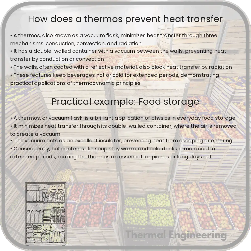
A thermos, also known as a vacuum flask, is an ingeniously designed container that keeps its contents hotter or colder than its surroundings, effectively slowing down the rate of heat transfer. This article will explore the science behind how a thermos can maintain the temperature of liquids stored inside it, focusing on the engineering principles that prevent heat transfer.

Principles of Heat Transfer

Heat can be transferred in three primary ways: conduction, convection, and radiation. Understanding these mechanisms is essential to appreciating how a thermos works:

  • Conduction is the transfer of heat through a material by direct contact.
  • Convection involves the transfer of heat by the movement of fluids (liquids or gases).
  • Radiation is the transfer of heat in the form of electromagnetic waves, such as visible light or infrared radiation.

The Design of a Thermos

The effectiveness of a thermos in maintaining the temperature of its contents comes from its specialized design that minimizes heat loss or gain by conduction, convection, and radiation. Here are the key components:

  1. Double-Walled Container: A thermos consists of two walls, typically made of glass or stainless steel, separated by a vacuum.
  2. Vacuum: The space between the two walls is evacuated of air, creating a vacuum. A vacuum is an excellent insulator because it lacks matter and therefore significantly reduces heat transfer by conduction or convection.
  3. Reflective Coating: The surfaces facing the vacuum are often coated with a reflective material, such as a thin layer of silver. This coating reflects heat radiation back towards its source, helping to prevent heat loss or gain through radiation.
  4. Sealed Lid: The lid of the thermos is tightly sealed to prevent the escape of heat by convection. It also minimizes the exchange of air between the inside of the thermos and the outside environment, further reducing heat transfer.

Overall Effectiveness

The combination of these design elements allows a thermos to effectively limit the three mechanisms of heat transfer. By reducing conduction through the use of a vacuum, limiting convection by sealing the lid tightly, and reflecting radiation with a metallic coating, a thermos can maintain the temperature of its contents far longer than a normal container could.

Applications

Thanks to their ability to control heat transfer efficiently, thermoses are widely used in everyday contexts where maintaining temperature is important. They are ideal for keeping hot drinks hot and cold drinks cold over extended periods, thus enhancing convenience and enjoyment. Furthermore, thermoses have scientific and medical applications where precise temperature control is crucial, such as transporting biological samples or pharmaceuticals.

In conclusion, the thermos is a masterful application of basic physical principles, specifically engineered to minimize heat transfer. This capability not only makes it invaluable in daily life but also in various industrial and scientific fields.

Principles of Fluid Statics Explained

Learn about fluid statics, the study of fluids at rest, covering pressure, buoyancy, and Pascal’s Law, key in engineering and physics.

Principles of Fluid Statics Explained

Understanding the Basics of Fluid Statics

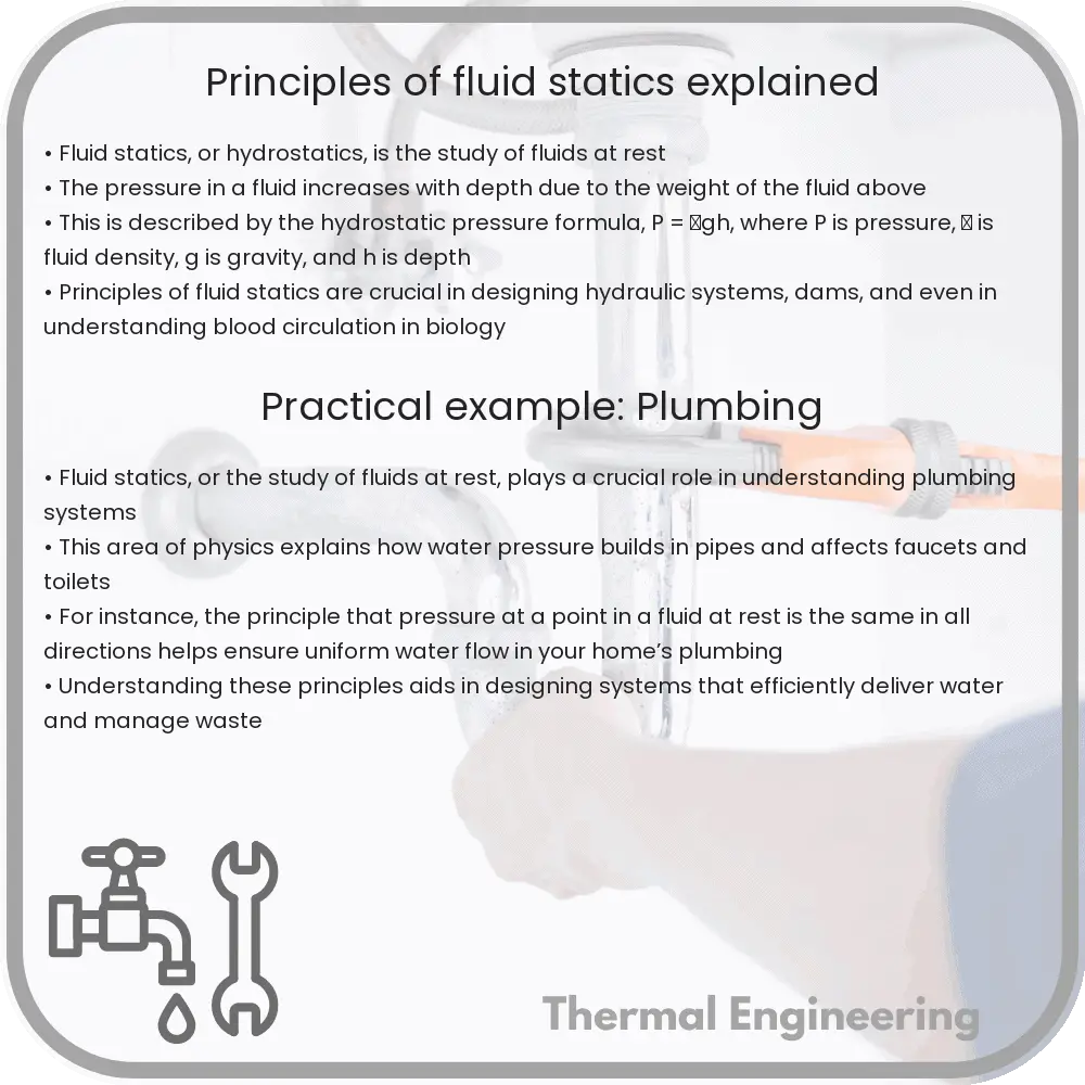
Fluid statics, often referred to as hydrostatics, is the branch of fluid mechanics that studies fluids at rest. It primarily deals with the consequences and implications of pressure in a fluid and how it varies in different conditions. This field is pivotal in engineering applications such as the design of dams, submarines, and hydraulic presses. In this article, we’ll explore the fundamental principles of fluid statics including pressure, buoyancy, and the application of Pascal’s Law.

Pressure in Fluids

Pressure is a significant concept in fluid statics and is defined as the force exerted per unit area. In fluids, pressure is exerted uniformly in all directions. The formula to calculate pressure (P) is:

P = F / A

Where F is the force applied and A is the area over which the force is distributed. Fluid pressure can also be described as hydrostatic pressure when dealing with liquids, expressed by the equation:

P = ρgh

Here, ρ (rho) is the fluid density, g is the acceleration due to gravity, and h is the height of the fluid column above the point in question. This equation highlights how pressure in a fluid increases with depth.

Buoyancy

Buoyancy, also known as the buoyant force, is the force that causes objects to float. When an object is submerged in a fluid, it experiences an upward force that opposes the weight of the object. This is due to the pressure difference at different depths. Archimedes’ Principle states that the buoyant force on a submerged object is equal to the weight of the fluid that the object displaces. Mathematically, it is expressed as:

Fb = ρf * Vdisp * g

Where Fb is the buoyant force, ρf is the density of the fluid, Vdisp is the volume of the fluid displaced by the object, and g is the acceleration due to gravity.

Pascal’s Law

Pascal’s Law states that a change in pressure applied to an enclosed fluid is transmitted undiminished to every point of the fluid and to the walls of its container. This principle is fundamental in hydraulic systems, which use fluid power to perform work. Hydraulic systems can be seen in various applications such as automotive brakes, aircraft hydraulics, and industrial machinery. The law is mathematically expressed as:

ΔP = ρgΔh

Where ΔP is the change in pressure, ρ is the density of the fluid, g is acceleration due to gravity, and Δh is the change in height.

Applications of Fluid Statics

The principles of fluid statics are extensively applied across various engineering fields. Some common applications include:

  • Hydraulic Lifts: Use Pascal’s Law to lift heavy loads in automotive and industrial applications.
  • Submarines: Use the principles of buoyancy to submerge and surface by controlling the volume of water in ballast tanks.
  • Water Supply Systems: Utilize hydrostatic pressure to supply water to different elevations in residential and commercial buildings.

Understanding the principles of fluid statics is essential for engineers and professionals in the field as it lays the foundation for analyzing and designing various fluid-based systems.

Conclusion

Fluid statics is a critical area of study in physics and engineering, providing insights into how fluids behave when at rest. Mastering the principles of pressure, buoyancy, and Pascal’s Law enables engineers to design more efficient systems and solve complex challenges in fluid mechanics. With its widespread applications ranging from simple mechanisms to complex industrial systems, fluid statics remains a fundamental topic for aspiring engineers.

How Do Siphons Work with Fluids?

Learn how siphons use atmospheric pressure and gravity to transfer liquids between containers, defying gravity by moving liquid uphill before descending.

How Do Siphons Work with Fluids?

Understanding the Mechanics of Siphons

A siphon is a simple yet fascinating device used to transfer liquids from one container to a lower container, using a tube that passes over an intermediate elevation without mechanical pumps. The mystique of siphons lies in their ability to move water, or any liquid, uphill before allowing it to continue its journey downward, seemingly defying gravity. To understand how siphons work, it’s crucial to explore the physics underlying this process.

The Basic Principle of a Siphon

At the core of a siphon’s operation is atmospheric pressure – the same force that makes drinking through a straw possible. A siphon works under the principle that the gravitational pull on the column of liquid on the longer side of the siphon tube, exiting the container, is greater than the pull on the shorter side entering the container. This imbalance in forces causes the liquid to move from the higher reservoir over the top of the siphon to the lower one.

How a Siphon Starts

To initiate a siphon, the entire tube must first be filled with the liquid. This can often be accomplished by submerging the siphon in the liquid until it is completely filled, with both ends temporarily sealed to contain the liquid. Once placed with one end in the donor container and the other in the receiver container, and assuming the end point is lower than the starting point, releasing the seal allows the siphon to begin operating. The atmospheric pressure outside the tube pushes liquid up from the donor container, while gravity pulls the rest of the liquid down to the receiver container, thereby maintaining the flow.

Crucial Factors Affecting Siphon Operation

  • Height of the Crest: The peak point, or crest, of the siphon should not exceed approximately 10 meters for water siphons. Beyond this height, the pressure inside the siphon drops below the vapor pressure of water, causing the formation of air bubbles and breaking the column of water.
  • Difference in Height: The exit point of the siphon tube must be lower than the liquid level in the source container for gravity to facilitate the siphoning effect effectively.
  • Tube Diameter: The flow rate of the liquid depends on the diameter of the tube; a wider tube allows for a higher flow rate.

Examples and Applications

Siphons find applications in various fields, demonstrating their versatility and efficiency:

  1. Aquarium Maintenance: Siphons are commonly used to remove old water from aquariums without disturbing the fish or the setup.
  2. Fuel Transfer: In situations where fuel needs to be transferred from a larger container to a vehicle or storage facility, siphons provide a simple and efficient solution.
  3. Agricultural Irrigation: Large scale siphons can help divert water from reservoirs to agricultural fields, aiding in irrigation.
  4. Chemical Processes: In chemical plants, siphons help transfer volatile or corrosive liquids from one container to another, minimizing human contact with the chemicals.

Overall, the operation of a siphon is a beautiful demonstration of atmospheric pressure and gravity at work. By harnessing these natural forces, siphons perform the seemingly magical feat of moving liquids up and over obstacles, proving essential in both household and industrial applications.

What Is Darcy’s Law in Fluid Flow?

Darcy’s Law is a key principle in fluid mechanics, crucial for analyzing fluid flow through porous media in fields like hydrogeology and civil engineering.

What Is Darcy's Law in Fluid Flow?

Understanding Darcy’s Law in Fluid Flow

Darcy’s Law is a fundamental principle in hydrogeology and civil engineering that describes the flow of fluid through a porous medium. This law is particularly crucial in applications involving groundwater flow, oil recovery, and filtration processes. This article explains the basics of Darcy’s Law, how it is applied, and why it is a cornerstone in the study of fluid flow through porous materials.

The Basics of Darcy’s Law

Darcy’s Law was formulated by Henry Darcy in 1856 through a series of experiments dealing with the flow of water through beds of sand. The law provides a quantitative description of the flow of fluids (typically liquids) through a porous medium. It defines the flow rate dependent on the properties of the fluid and the medium.

The Equation

The mathematical expression of Darcy’s Law can be written as:

Q = -KA(dh/dl)

Where:

  • Q is the volumetric flow rate of the fluid (how much fluid flows per unit time), typically measured in cubic meters per second (m³/s).
  • K is the hydraulic conductivity of the medium (a measure of how easily a fluid can move through the porous medium), measured in meters per second (m/s).
  • A is the cross-sectional area through which the fluid flows, measured in square meters (m²).
  • dh/dl is the hydraulic gradient, a dimensionless quantity representing the rate at which hydraulic head decreases over a given length of the medium.

The negative sign in the equation indicates that fluid flows from a region of higher hydraulic head to a region of lower hydraulic head, adhering to the principle that fluid moves due to a difference in pressure or gravitational potential.

Applications of Darcy’s Law

Darcy’s Law is widely used in various engineering and scientific fields, including:

  • Hydrogeology: For predicting the movement of groundwater, especially in aquifer recharge and the contamination studies.
  • Petroleum Engineering: In estimating the flow of oil and natural gasses through porous rock formations.
  • Environmental Engineering: For designing systems that control the movement and treatment of pollutants in soil and groundwater.
  • Agricultural Engineering: In managing irrigation and drainage systems to optimize water use efficiency.
  • Civil Engineering: Used in the design of filtration systems and the management of urban runoff and sewage.

Limitations of Darcy’s Law

While Darcy’s Law is a powerful tool in fluid mechanics, it has certain limitations:

  • It is generally applicable only for laminar flow conditions and may not predict accurate results under turbulent flow conditions.
  • It assumes the porous medium is homogenous and isotropic, which is not always the case in natural formations.
  • The hydraulic conductivity can vary with the saturation of the medium, a factor not directly accounted for in the basic form of Darcy’s Law.

In conclusion, Darcy’s Law provides a fundamental and practical approach to understanding and calculating the flow of fluids through porous media. Although it has limitations, the law is integral to many scientific and engineering applications related to fluid flow in natural and artificial systems.

Basics of Computational Fluid Dynamics

Learn about Computational Fluid Dynamics (CFD), a method using numerical analysis to solve fluid flow problems across diverse industries.

Basics of Computational Fluid Dynamics

Introduction to Computational Fluid Dynamics

Computational Fluid Dynamics (CFD) is a branch of fluid mechanics that uses numerical analysis and algorithms to solve problems involving fluid flows. Computers are used to perform the calculations necessary to simulate the interaction of liquids and gases with surfaces defined by boundary conditions. With high-speed supercomputers, CFD enables the analysis of complex problems involving fluid-fluid, fluid-solid, or fluid-gas interactions.

Basic Principles of CFD

At its core, CFD solves the Navier-Stokes equations, which describe the motion of fluid substances. These equations are a set of nonlinear partial differential equations derived from the conservation laws of physics: the conservation of mass, momentum, and energy. CFD analysis typically involves three major steps:

  • Pre-processing: This step involves the creation of a geometric model of the problem domain and the establishment of boundary conditions, material properties, and the aspects of the fluid flow (temperature, velocity, pressure, etc.).
  • Solving: During this step, the solver uses numerical methods to convert the partial differential equations into algebraic equations which can be solved using computational algorithms. Methods such as Finite Volume, Finite Element, and Finite Difference are typically used.
  • Post-processing: The final step involves the visual analysis of the results. Engineers use various visualization tools to interpret the behavior of the fluid dynamics within the modeled scenario.

Key Numerical Methods in CFD

CFD utilizes several numerical methods to solve the equations that describe fluid flow. The most commonly used methods include:

  • Finite Difference Method (FDM): This method involves approximating the differential equations by finite difference equations on a grid.
  • Finite Volume Method (FVM): Widely used due to its conservation properties, FVM calculates fluxes through the finite volume cell boundaries to ensure conservation laws are satisfied.
  • Finite Element Method (FEM): FEM subdivides the problem domain into smaller parts (‘elements’). It is particularly well-suited for complex geometries.

Applications of Computational Fluid Dynamics

CFD is a versatile tool that is used in a wide range of applications across various industries, including:

  • Aerospace: For designing aircraft components, studying aerodynamic forces, and optimizing flight conditions.
  • Automotive: Used in designing more aerodynamically efficient vehicles, and in the study of fuel air mixing in combustion engines.
  • Energy: In the design and optimization of systems like turbines, boilers, and heat exchangers.
  • Environmental Engineering: For studying pollution dispersion, wind environment around buildings, and river flows.
  • Biomedical Engineering: Used to model blood flow in the human cardiovascular system, airflow in the respiratory system, etc.

Challenges in CFD

Despite its extensive applications, CFD faces several challenges that researchers and engineers are continually trying to overcome. These include:

  • High Computational Cost: Simulating complex phenomena often requires substantial computational power and time, especially for turbulent flows and three-dimensional geometries.
  • Accuracy and Validity: The accuracy of a CFD simulation depends on the fidelity of the physical models and the fineness of the computational mesh. Ensuring accurate and validated results can be difficult and requires competent handling.

Conclusion

Computational Fluid Dynamics stands as a crucial tool in the analysis of fluid flows in various engineering fields. By understanding and applying CFD, engineers can simulate and predict fluid behavior in real-world applications, leading to more efficient and innovative designs. As computational power increases and algorithms become more refined, the scope and capability of CFD are expected to expand, offering even more possibilities in engineering solutions.

How Do Fluids Affect Aerodynamic Shapes?

Learn how fluid dynamics impacts aerodynamic shapes in vehicles and technology, enhancing efficiency and performance.

How Do Fluids Affect Aerodynamic Shapes?

Understanding the Impact of Fluids on Aerodynamic Shapes

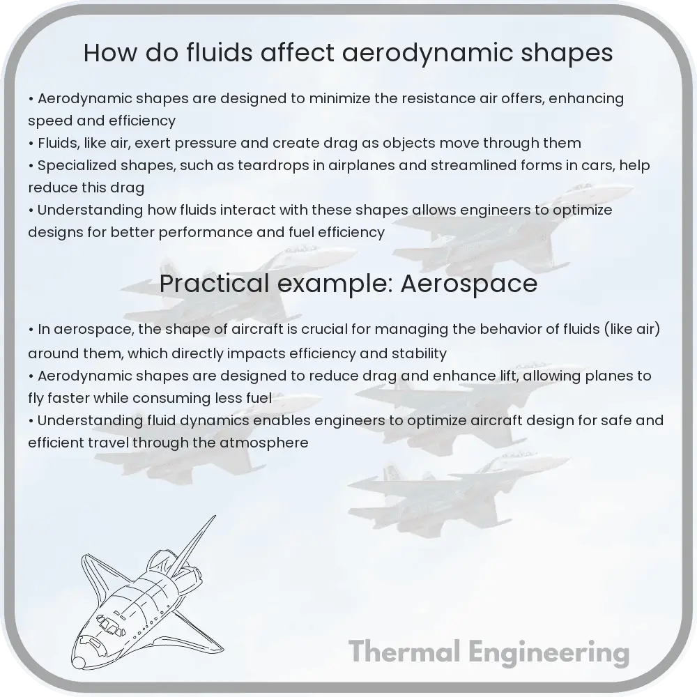
Aerodynamics is a fascinating branch of physics and engineering that explores how gases interact with moving objects. When it comes to understanding how fluids affect aerodynamic shapes, such as those of airplanes, cars, and trains, it’s essential to grasp some basic principles of fluid dynamics—the study of fluids (liquids and gases) in motion.

Basics of Fluid Dynamics

Fluid dynamics examines the behaviors of liquids and gases in motion. The fundamental equations governing these behaviors are the Navier-Stokes equations, which account for changes in velocity, pressure, temperature, and density of the fluid. These properties play a critical role in shaping the interactions between the fluid and objects of various shapes.

Pressure Differences and Boundary Layers

When a fluid such as air flows over the surface of an aerodynamic shape, it creates variations in pressure on the surface of the object. High-speed flows tend to lower pressure, while slower flows increase it. This variation in pressure around different parts of an object helps generate lift in aerodynamic shapes like airplane wings.

Accompanying the pressure changes, boundary layers form near the surface. These are thin layers of fluid where viscous forces are significant, affecting the overall aerodynamic performance. Engineers design surfaces to influence the behavior of these boundary layers to minimize drag (resistance offered by the air) and optimize lift.

Streamlining Aerodynamic Shapes

The design of aerodynamic shapes is often streamlined to reduce the drag. Streamlining shapes allow the fluid to flow smoothly over the object, diminishing the size and effects of wake—the region of recirculating flow immediately behind the moving object. Reduced wake leads to lower drag. Understanding the characteristics of fluid flow and the Reynolds number (a dimensionless quantity that helps predict flow patterns in different fluid flow situations) assists engineers in enhancing efficiencies for various transportation modes.

Effects of Turbulence

Turbulence refers to complex, irregular fluid movements that can dramatically influence the efficiency of aerodynamic shapes. It increases drag but can sometimes contribute to stabilizing the flow and increasing lift. Turbulent flow is characterized by chaotic changes in pressure and flow velocity. Engineers and scientists use various devices like spoilers on cars or vortex generators on airplane wings to manage and manipulate turbulence to achieve desired aerodynamic qualities.

Application in Design

Every aspect of an aerodynamic object’s design, from its overall shape to the texture of its surface, teems with considerations about how fluids interact with these features. Whether it’s the sleek design of a sports car or the wing configuration on an aircraft, fluid dynamics influence crucial design decisions. These decisions can affect speed, fuel efficiency, stability, and the ability to control the vehicle effectively in air or on the road.

Understanding how fluids interact with different shapes not only helps in designing efficient vehicles and other systems but also enhances our grasp of natural phenomena such as wind flow patterns and weather formations. This knowledge is invaluable in diverse fields from climatology to urban planning, showcasing the vast applicability of fluid dynamics in real-world situations.

In conclusion, the study of how fluids affect aerodynamic shapes is a cornerstone of aerodynamics and fluid dynamics and is essential for the advancement of technology in fields such as aviation, automotive industry, and even environmental science. By mastering the fundamentals of this interaction, engineers can continue to innovate and improve the performance and efficiency of various technologies in our everyday lives.