Facebook Instagram Youtube Twitter

Understanding Buoyancy in Fluids

Explore the concept of buoyancy, its fundamental principles, applications across engineering fields, and factors influencing an object’s ability to float.
Understanding Buoyancy in Fluids

Understanding Buoyancy in Fluids

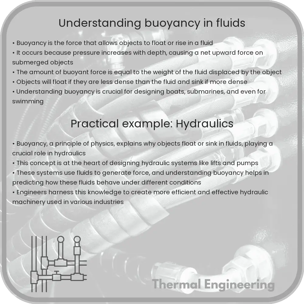
Buoyancy is a fundamental concept in fluid mechanics, which describes the ability of a fluid to exert an upward force on a body placed in it. This force enables objects, ranging from boats to balloons, to float or rise depending on their relative densities to the fluid. The principle of buoyancy is essential for applications in engineering, including ship design, underwater exploration, and fluid transport systems.

The Principle of Buoyancy

The principle of buoyancy, also known as Archimedes’ principle, states that the buoyant force (upward force) exerted on a body immersed in a fluid is equal to the weight of the fluid that the body displaces. This principle can be formally expressed with the equation:

Fb = ρ * V * g

  • Fb is the buoyant force
  • ρ (rho) is the density of the fluid
  • V is the volume of fluid displaced by the object
  • g is the acceleration due to gravity

The density of the object relative to the density of the fluid determines whether it will float or sink. If the object’s density is less than the fluid’s density, it will float; if it’s greater, it will sink.

Applications of Buoyancy

Buoyancy has a wide range of practical applications across different fields of engineering:

  1. Naval Engineering: The design and construction of ships and submarines heavily rely on understanding buoyancy. Engineers must calculate the buoyant force to design vessels that can float stably and carry loads efficiently.
  2. Civil Engineering: In projects involving water supply and sewage systems, engineers use principles of buoyancy to design pipelines and systems that maintain proper flow rates and direction.
  3. Aerospace Engineering: For aircraft and spacecraft, buoyancy is considered in contexts such as the design of airships and balloons which use lighter-than-air gases to lift off from the ground.
  4. Environmental Engineering: Remediation techniques such as air sparging (injecting air into groundwater to remove contaminants) are based on buoyancy effects.

Factors Influencing Buoyancy

Several factors can influence buoyancy and the ability of an object to float:

  • Density of the Fluid: The denser the fluid, the greater the buoyant force. For instance, objects are more buoyant in saltwater than in freshwater.
  • Temperature: The temperature can affect the density of a fluid. Generally, as the temperature increases, the density of a fluid decreases, slightly altering the buoyant force.
  • Salinity: In bodies of water, the level of salinity can impact bouyancy. Higher salinity increases water density, and hence, the buoyant force.
  • Volume of the Object: Increasing an object’s volume without changing its mass will decrease its density, leading to greater buoyancy.

Conclusion

Understanding buoyancy is crucial not only in engineering but also in everyday life, explaining phenomena from why ice floats in your drink to how enormous ships cruise across oceans. Whether you are an engineering student, a professional in the field, or simply a curious mind, grasping the basics of buoyancy can provide deeper insights into how the physical world operates and how human innovation continues to interact with it.


Fluid Mechanics: Understanding Drag Forces

Learn about drag forces in fluid mechanics, crucial for designing vehicles, aircraft, and more, focusing on pressure and skin friction drag.

Fluid Mechanics: Understanding Drag Forces

Fluid Mechanics: Understanding Drag Forces

Drag forces are a fundamental concept in fluid mechanics, which is the study of how fluids (liquids and gases) behave when they are in motion, and when they interact with solid objects. In practical terms, the understanding of drag forces is crucial in designing vehicles, aircraft, and maritime vessels, as well as in many sports and engineering applications.

What is Drag?

Drag is a force that opposes the motion of an object through a fluid. This resistance is caused by the interaction between the fluid and the surface of the moving object. When an object moves through a fluid, it has to push the fluid particles out of the way, which takes energy and results in a force that slows the motion of the object. This slowing force is what we call drag.

Types of Drag

There are mainly two types of drag: pressure drag and skin friction drag:

  • Pressure Drag: It arises due to the pressure differential between the front and the back of the object moving through the fluid. It is highly influenced by the shape of the object. Blunt or non-streamlined objects typically face higher pressure drag.
  • Skin Friction Drag: It is caused by the viscosity of the fluid. The fluid “sticks” to the surface of the object and creates a layer where the fluid velocity changes from zero at the object’s surface to the free stream velocity of the fluid. This layer is known as the boundary layer. The shear forces within this layer contribute to the skin friction drag.

Calculating Drag Force

The drag force (FD) can be calculated using the drag equation:

FD = (1/2) * ρ * v2 * CD * A

  1. ρ (Rho): The fluid density
  2. v: The velocity of the object relative to the fluid
  3. CD (Drag Coefficient): A dimensionless number that depends on the shape of the object and the flow conditions of the fluid
  4. A: The reference area (this is typically the frontal area of the object)

Factors Affecting Drag Coefficient

The drag coefficient, CD, is not a constant and varies according to several factors:

  • Shape of the Object: Streamlined objects typically have lower drag coefficients compared to blunt objects.
  • Surface Roughness: Smoother surfaces generally produce less skin friction drag compared to rough surfaces.
  • Reynolds Number: This non-dimensional number characterizes the flow of the fluid around the object and is defined as the ratio of inertial forces to viscous forces within the flow. It depends on the velocity of the fluid, the characteristic length/diameter of the object, and the kinematic viscosity of the fluid.

Real-World Applications

Understanding drag forces allows engineers to design more efficient vehicles by reducing energy consumption and increasing performance. For example, the aerodynamics of cars and aircraft are optimized to minimize drag, thereby improving fuel efficiency. In sports, athletes wear streamlined clothing to reduce resistance and enhance performance. In maritime engineering, ship hulls are designed to reduce drag, promoting speed and reducing fuel consumption.

In summary, drag forces play a crucial role in various engineering disciplines by influencing design and efficiency. Mastery of fluid mechanics and understanding of drag can lead to innovations that significantly impact our daily interactions with technology and the environment.

How Do Propellers Generate Thrust?

Learn how propellers use fluid dynamics and pressure principles to generate thrust in various transport modes.

How Do Propellers Generate Thrust?

How Do Propellers Generate Thrust? Understanding Fluid Pressure and Its Effects

Propellers are a common sight in various modes of transport, from boats to airplanes. These devices play a crucial role in motion by converting rotational power into thrust. But how exactly does this process work? The secret lies in understanding fluid dynamics and the principles of pressure and force.

The Basics of Propeller Design

At its core, a propeller is a type of fan that transmits power by converting rotational motion into thrust. This is done through its blades which are shaped to push air or water backwards. The shape and twist of the blades are critical and are designed to maximize efficiency while minimizing drag.

The Role of Fluid Pressure

The principle behind a propeller’s function involves fluid pressure and the movement of the fluid, whether air or water. When a propeller rotates, its blades push against the fluid, causing the fluid to accelerate backwards. According to Newton’s Third Law, every action has an equal and opposite reaction. As the blades push the fluid backwards, the fluid similarly exerts an equal and opposite force on the propeller blades, propelling the vehicle forward.

Dynamic Lift Created by Propeller Blades

Each blade of a propeller has an airfoil shape, similar to an airplane wing. This design allows each blade to create lift as it moves through the fluid. Lift in the context of propellers is the force that moves the vehicle forward. The lift generated by each blade can be described by Bernoulli’s principle, which states that an increase in the speed of the fluid occurs simultaneously with a decrease in pressure.

As the propeller rotates, the angle (also known as pitch) of the blades and their speed cause the fluid to accelerate over the blade creating a difference in pressure across the surfaces of the blade. The higher pressure on the bottom and lower pressure on the top push the blade upward and forward, thereby generating thrust. The equation for lift (L) can be expressed as:

L = (1/2) * ρ * v² * A * Cl

  • ρ (rho): Density of the fluid
  • v: Velocity of the fluid relative to the propeller
  • A: Area of the propeller blade
  • Cl: Lift coefficient, which depends on the blade shape and angle of attack

Thrust Equation in Propellers

The thrust (T) created by a propeller can again be approximated by a variation of Bernoulli’s principle and can be thought of in terms of changes in the momentum of the fluid. The thrust generated by the propeller can be calculated using the following equation:

T = ṁ * (Vout – Vin)

  • ṁ (m dot): Mass flow rate of the fluid through the propeller
  • Vout: Velocity of the fluid leaving the propeller zone
  • Vin: Velocity of the fluid entering the propeller zone

This equation essentially says that the thrust generated is the product of the mass flow rate and the change in velocity of the fluid passing through the propeller. As the propeller imparts more speed to the fluid, more thrust is generated.

Conclusion

Understanding how propellers generate thrust is a classic example of fluid dynamics in action, involving concepts of pressure, fluid velocity, and aerodynamics. Engineers design propellers by carefully considering the shape, size, and pitch of the blades to optimize the interaction with the fluid, maximizing thrust while minimizing energy loss. Learning about these principles not only reveals the mechanics behind everyday technology but also provides insights into sophisticated engineering design strategies.

This fundamental understanding allows engineers and designers to innovate and improve upon existing technologies, crafting more efficient and powerful propelling systems for everything from personal drones to large maritime vessels.

What Is Laminar vs. Turbulent Flow?

Explore the differences between laminar flow and turbulent flow in fluid dynamics, focusing on their characteristics, mathematical descriptions, and engineering applications.

What Is Laminar vs. Turbulent Flow?

Understanding Laminar vs. Turbulent Flow in Fluid Dynamics

In the field of fluid dynamics, the behavior of liquids and gases in motion is a fundamental area of study. A significant aspect of this study is understanding the difference between laminar and turbulent flow. These two types of flow are characterized by their different patterns and behaviors, which have important implications in engineering and scientific applications.

What is Laminar Flow?

Laminar flow, often referred to as streamline flow, occurs when a fluid flows in smooth, parallel layers, with minimal mixing between them. The fluid moves along well-defined paths or streamlines, and there is no lateral mixing across the layers. This type of flow is typically characterized by a lower flow velocity and higher viscosity.

Mathematically, laminar flow can be described by the Reynolds number (Re), which is a dimensionless quantity used to predict flow patterns in different fluid flow situations. For flow in a pipe, laminar flow generally occurs at a Reynolds number less than 2000:

Re = (ρ * v * D) / μ

where ρ is the density of the fluid, v is the flow velocity, D is the diameter of the pipe, and μ is the dynamic viscosity of the fluid.

What is Turbulent Flow?

Contrasting sharply with laminar flow, turbulent flow is characterized by chaotic, irregular fluid motion. In turbulent flow, eddies, swirls, and other disturbances are generated, leading to a high degree of mixing of the fluid. This type of flow typically occurs at higher velocities and with fluids of lower viscosity.

Turbulent flow is also described by the Reynolds number, generally occurring when the Reynolds number is greater than 4000. In turbulent flow, the fluid no longer moves in layers, but instead mixes laterally and vertically.

Comparison Between Laminar and Turbulent Flow

  • Smooth vs. Chaotic: Laminar flow is smooth and orderly while turbulent flow is chaotic and irregular.
  • Reynolds Number: Laminar flow occurs at lower Reynolds numbers (<2000), while turbulent flow occurs at higher Reynolds numbers (>4000).
  • Fluid Viscosity: Higher viscosity favors laminar flow, whereas lower viscosity is more conducive to turbulent flow.
  • Efficiency: Laminar flow is generally more energy-efficient due to less frictional energy loss compared to turbulent flow.

Applications of Laminar and Turbulent Flow

Both laminar and turbulent flows have their specific applications in engineering and technology:

  • Laminar Flow: Used in applications where it is essential to control the flow precisely, such as in the aeronautical and biomedical engineering fields. For example, the design of blood flow devices, including stents and catheters.
  • Turbulent Flow: Although more challenging to predict and control, turbulent flow enhances mixing and heat transfer. It is beneficial in combustion engines and in heat exchangers in power plants and chemical processing equipment.

Understanding these two types of flow is crucial for the design and operation of various systems in engineering. Knowledge about whether a flow will be laminar or turbulent helps engineers predict how fluids will behave in different situations, leading to more efficient and effective designs.

Principles of Thermal Insulation Materials

Learn about thermal insulation materials, their types, functionalities, and the principles influencing their effectiveness in various industries.

Principles of Thermal Insulation Materials

Understanding the Principles of Thermal Insulation Materials

Thermal insulation materials play a critical role in reducing the heat transfer between objects in thermal contact or in range of radiative influence. They can be used in a variety of applications, from building insulation and refrigeration to automotive and aerospace industries. This article explores how these materials function, their types, and what physical principles govern their effectiveness.

How Thermal Insulation Works

Thermal insulation works based on the principle of minimizing heat flow. Heat can be transferred in three ways: conduction, convection, and radiation. Effective insulation materials essentially slow down the flow of heat, and they are evaluated based on their thermal conductivity or R-values (the higher the R-value, the better the insulation).

  • Conduction: This is the heat transfer via direct molecular collision. An insulating material with low thermal conductivity hinders the movement of heat energy from one molecule to another.
  • Convection: This involves the heat transfer through fluids (liquids or gases). Insulation materials minimize convective currents by trapping air or other gases.
  • Radiation: Radiative heat transfer occurs via electromagnetic waves. Insulative materials with reflective surfaces such as foils can reflect radiant heat, while dense materials absorb and re-radiate heat slowly.

Types of Thermal Insulation Materials

There are several types of thermal insulation materials, each with unique properties and suited to specific applications:

  1. Fibrous Insulators: Materials such as fiberglass, rock wool, and slag wool. These insulators contain small diameter fibers that trap air, reducing convection and conduction.
  2. Cellular Insulators: Materials like polystyrene, polyurethane, and polyisocyanurate. These are composed of small individual cells that trap gases to impede convective heat transfer.
  3. Granular Insulators: Consist of small nodules which contain air pockets. Examples include perlite and vermiculite.
  4. Reflective Systems: Often used alongside other insulation types, reflective systems such as aluminum foils are designed to block radiant heat.

Key Properties of Insulation Materials

The effectiveness of insulation is determined by several key properties:

  • Thermal Conductivity (λ): Indicates the material’s inherent ability to conduct heat. Lower thermal conductivity values represent better insulation properties.
  • Density: Denser materials can store more heat, but this could also aid in heat transfer through conduction.
  • Specific Heat Capacity: This is the amount of heat per unit mass required to raise the temperature by one degree Celsius. Materials with a high specific heat capacity can absorb more heat before they become warmer.
  • Moisture Resistance: Moisture can drastically affect the performance of insulation materials. Some materials are more resistant to moisture than others, thus maintaining their insulative properties under damp conditions.
  • Fire Resistance: In some applications, it is crucial for the insulation to be fire-resistant. Materials that do not burn readily and have slow flame spread rates are preferred in these cases.

The Future of Thermal Insulation

Advancements in material science continue to improve the properties of thermal insulation materials. Innovations such as aerogels and vacuum insulation panels represent the next generation of insulators that offer higher thermal resistance with thinner profiles and lighter weight. Understanding and choosing the right kind of thermal insulation depends on a thorough grasp of the basic principles and the specific requirements of the application.

The ongoing research and development in this field are aimed at creating more efficient, sustainable, and cost-effective insulation solutions that meet the increasing demands of modern energy conservation standards and help mitigate the environmental impacts of energy use.

Heat transfer enhancement in solar collectors

Enhancing heat transfer in solar collectors improves efficiency and sustainability of solar energy systems.

Heat transfer enhancement in solar collectors

Heat Transfer Enhancement in Solar Collectors

One of the critical components in the efficiency of solar collectors, such as solar water heaters and photovoltaic panels, is the effectiveness of heat transfer. Enhancing heat transfer allows for improved performance, which can significantly affect the overall energy efficiency and cost-effectiveness of solar energy systems. This article explores the various methods and technologies used to enhance heat transfer in solar collectors.

Understanding Heat Transfer Mechanisms

Heat transfer in solar collectors primarily occurs through convection, conduction, and radiation. The sun radiates energy onto the collector surface, which absorbs this energy and transfers it to a heat transfer fluid (HTF) via conduction. The warm HTF then circulates through the system by convection, transferring the heat for practical use or storage.

Techniques to Enhance Heat Transfer

  • Nano-fluids: Adding nanoparticles to the heat transfer fluid is a modern technique to enhance the thermal conductivity of the fluid. Nano-fluids can significantly increase heat absorption and thermal conductivity compared to conventional fluids, resulting in higher efficiency.
  • Selective Coatings: Applying selective coatings on the collector surface can enhance its heat absorption abilities while reducing radiative losses. These coatings are designed to be highly absorptive to solar radiation and low emittive in the infrared spectrum.
  • Improved Geometries: Modifying the shape and design of the heat collector elements can optimize the surface area and the flow pattern across it. For instance, corrugated or finned tubes can increase the surface area, thus enhancing the heat transfer rate.

Passive and Active Techniques

Heat transfer in solar collectors can be enhanced using either passive or active methods:

  • Passive techniques involve structural or material changes that naturally improve performance without consuming additional energy. Examples are integrating phase change materials (PCMs), using microchannels, or improving the thermo-physical properties of the collector materials.
  • Active techniques involve external energy inputs, such as using pumps to improve the HTF flow or employing external magnetic fields when using ferrofluids. While these methods can significantly enhance heat transfer, they also increase the system’s complexity and energy consumption.

Recent Advances and Research

Recent research in heat transfer enhancement in solar collectors is focused on optimizing materials and designs to achieve maximum efficiency. For example, the development of translucent insulation materials (TIMs) allows for better trapping of solar radiation with minimal thermal losses. Another promising area is the use of biologically inspired designs, like biomimetic surfaces, to reduce flow resistance and enhance convective heat transfer.

In conclusion, enhancing heat transfer in solar collectors involves a combination of advanced materials, innovative designs, and sometimes, active intervention systems. These enhancements not only improve the efficiency of solar collectors but also contribute to the broader adoption of solar energy technologies by making them more cost-effective and efficient.

Implications for Energy Sustainability

Improvements in heat transfer technology for solar collectors hold significant potential for reducing global dependency on fossil fuels and enhancing energy sustainability. By increasing the efficiency of solar systems, more locales can feasibly adopt solar power as a substantial part of their energy mix, thereby contributing to environmental conservation and sustainability.

How Does Underfloor Heating Spread Heat?

Learn how underfloor heating systems distribute heat efficiently and offer benefits over traditional heating methods.

How Does Underfloor Heating Spread Heat?

Understanding How Underfloor Heating Spreads Heat

Underfloor heating is a sophisticated and efficient method for heating homes and buildings. This system uses either electrical coils or water-filled pipes, laid beneath the floor, to provide warmth directly from the ground up. Understanding the heat distribution mechanism of underfloor heating helps in appreciating its efficiency and comfort compared to traditional heating systems like radiators.

Types of Underfloor Heating Systems

There are two main types of underfloor heating systems:

  • Electric Underfloor Heating: This system uses electric wires or mats that generate heat when electricity passes through them.
  • Hydronic (Water) Underfloor Heating: This type uses a network of pipes laid under the floor through which heated water is circulated.

How Heat is Spread Through Underfloor Heating

The key to the efficiency of underfloor heating lies in the way it distributes heat. Unlike traditional radiators that heat the air around them, underfloor heating warms the lower part of the room and the surfaces with which it comes into contact directly. Here’s a step-by-step explanation:

  1. Conduction: Heat transfer occurs initially via conduction, where heat travels from the hot surface of the floor directly to any colder surface it touches.
  2. Radiation: As the floor itself gets warm, it also begins to radiate heat upwards into the room. This radiant heat provides a uniform warmth that rises evenly across the entire space.
  3. Convection: Finally, the warm air naturally rises through the process of convection, further helping to circulate warmth throughout the room.

The design of underfloor heating closely adheres to the principles of thermal comfort and energy efficiency. It uniformly heats a room and maintains consistent temperature distribution from the floor up, contrasting sharply with traditional systems where heat accumulates at the ceiling or near the heating source.

Factors Affecting the Efficiency of Underfloor Heating

Several factors influence how effectively an underfloor heating system spreads heat throughout a space:

  • Flooring Materials: Different materials have varying thermal conductivities. Tile and stone have high conductivity, making them excellent for heat transfer, while wood and carpet have lower conductivity rates.
  • Installation: Proper installation is crucial. Insulating layers beneath the heating elements can prevent heat loss to the subfloor, ensuring more heat is directed upwards into the living space.
  • Temperature Settings: Efficient underfloor heating should not require extremely high temperatures. It operates best at a consistent, moderate temperature, utilizing the thermal mass of the flooring material to store and gradually release heat.

Benefits of Underfloor Heating

Underfloor heating systems offer multiple benefits over traditional heating methods:

  • Energy Efficiency: They can be more energy-efficient by operating at lower temperatures while delivering the same level of comfort as higher-temperature conventional heaters.
  • Space Saving: As the heating components are hidden underneath the floor, they save space that would otherwise be occupied by radiators.
  • Improved Comfort: Heat is distributed evenly, eliminating hot spots and cold drafts typically associated with conventional heating methods.

In conclusion, the method by which underfloor heating spreads heat not only makes it an effective and comfortable heating solution but also a preferable choice for new construction and renovations. By understanding the core principles behind its operation, homeowners can make informed decisions about their heating needs and maximize the system’s efficiency and benefits.

What Is a Heat Sink and How Does It Work?

Learn how heat sinks effectively manage and disperse heat in electronic devices to prevent overheating and enhance device longevity.

What Is a Heat Sink and How Does It Work?

What Is a Heat Sink and How Does It Work?

A heat sink is an essential component in electronic systems and computers, designed to manage and disperse the heat generated by electronic devices such as CPUs, GPUs, and power transistors. By effectively dissipating the excess heat, heat sinks prevent overheating, enhancing the overall efficiency and longevity of devices. Understanding the structure, types, and function of heat sinks is key to appreciating their role in modern technology.

Structure of a Heat Sink

Typically, a heat sink is made from metals with high thermal conductivity, such as aluminum or copper, to facilitate quick heat transfer. The basic structure includes a base that contacts the heat source and an array of extended surfaces—or fins—that increase the heat sink’s surface area, thus improving its ability to dissipate heat to the surrounding environment.

How Heat Sinks Work

The operation of a heat sink revolves around the principles of thermal management through conduction and convection:

  • Conduction: Heat is initially transferred from the hot device to the cooler heat sink through conduction. This happens when heat moves from a high-temperature area (the device) to a lower temperature area (the base of the heat sink).
  • Convection: Once the heat is conducted to the heat sink, it needs to be dissipated effectively into the surrounding environment. This is accomplished by the fins of the heat sink, where heat is transferred to the air through convection. In simpler terms, the heat is carried away by air molecules that come into contact with the heated fins.

In many cases, a fan is used in conjunction with a heat sink to enhance the convection process. This is known as forced convection and is particularly effective in rapidly moving heat away from the heat sink, which is beneficial in tightly-packed electronic environments like computers or servers.

Types of Heat Sinks

Heat sinks can be categorized based on their manufacturing methods, materials used, and whether they are used with a fan (active) or without a fan (passive):

  1. Stamped Heat Sinks: These are made by stamping sheets of metal into the desired shape. They are generally used in applications where the heat load is lower.
  2. Extruded Heat Sinks: This type involves extruding metal, typically aluminum, through a die. Extruded heat sinks are common due to their cost-effectiveness and good thermal performance.
  3. Forged Heat Sinks: Forging can produce heat sinks with improved mechanical and thermal properties. They are used in more demanding situations where better heat dissipation is needed.
  4. Machined Heat Sinks: These are typically used for complex or custom shapes where precision is crucial. They can be made from either aluminum or copper and allow for optimized thermal performance.

Understanding the specific types and functions of heat sinks helps in selecting the right one for the application, ensuring efficient heat management in electronic devices.

Conclusion

Heat sinks are critical for preventing overheating in electronic devices, ensuring they operate within safe temperature limits. By effectively managing heat through conduction and convection, heat sinks maintain the performance and reliability of electronic systems. Whether in everyday computing devices or in large industrial applications, heat sinks play an indispensable role in technology.

How Do Thermocouples Measure Temperature?

Explore how thermocouples function as reliable temperature sensors across diverse applications, utilizing the Seebeck effect to measure thermal variations.

How Do Thermocouples Measure Temperature?

Understanding Thermocouples and Temperature Measurement

Thermocouples are a widely used type of temperature sensor for measurement and control and can also be used to convert thermal potential difference into electrical potential difference. They are inexpensive, interchangeable, and have standard connectors, and can measure a wide range of temperatures. Unlike most other methods of temperature measurement, thermocouples are self-powered and require no external form of excitation.

What is a Thermocouple?

A thermocouple consists of two wire legs made from different metals. The wires legs are welded together at one end, creating a junction. This junction is where the temperature is measured. When the junction experiences a change in temperature, a voltage (known as thermoelectric voltage) is created. The other end of these wire legs is connected to a measurement system. The difference in voltage between the two ends of the wires can then be interpreted as a temperature measurement.

How Does a Thermocouple Work?

The functionality of a thermocouple relies on the Seebeck effect, discovered in 1821 by Thomas Johann Seebeck. Essentially, when two different or dissimilar metals or alloys are joined together at one end, and there is a temperature difference between the joined end and the other ends, a voltage is generated that can be correlated directly to the temperature.

Mathematically, the voltage (V) generated by the thermocouple is directly proportional to the difference in temperature (\(\Delta T\)) between the hot junction and the reference (cold) junction:

\[ V \propto \Delta T \]

This effect is used to measure the temperature difference from the reference point to the point of interest.

Types of Thermocouples

Thermocouples come in various types, each made with specific metals that provide reliable measurements within certain temperature ranges and environments. The most common types are:

  • Type K (Nickel-Chromium / Nickel-Alumel): Versatile and cost-effective, suitable for a wide temperature range from -200°C to 1350°C.
  • Type J (Iron / Constantan): Affordable but with a smaller temperature range (-40°C to 750°C), and is susceptible to oxidation at higher temperatures.
  • Type T (Copper / Constantan): Good for measurements in moist environments and lower temperature ranges from -200°C to 350°C.
  • Type E (Nickel-Chromium / Constantan): Features a higher output than type K, making it suitable for lower temperature applications.
  • Type N (Nicrosil / Nisil): High stability and resistance to high-temperature oxidation, suitable for temperatures up to 1250°C.

Applications of Thermocouples

Given their versatility and range, thermocouples are used across various sectors. Some typical applications include:

  • Industrial sectors for monitoring process temperatures.
  • Consumer electronics for temperature control systems.
  • Automotive industries for checking engine and exhaust temperatures.
  • Aerospace for monitoring air and gas temperatures within engines.

Advantages and Limitations

Thermocouples offer several advantages such as simple design, low cost, wide temperature ranges, and quick response time. However, they do have limitations; they are less accurate than other temperature measurement devices like RTDs (Resistance Temperature Detectors) and can drift over time. Moreover, careful calibration is necessary to maintain accuracy, especially when used in critical applications.

In summary, thermocouples provide an essential tool for temperature measurement in many engineering and industrial applications. Their ability to measure a wide range of temperatures quickly and at relatively low cost makes them a go-to choice for many thermal monitoring tasks.

Understanding Radiative Heat Transfer

Learn about radiative heat transfer, a key concept in physics and engineering that involves the transmission of heat via electromagnetic waves.

Understanding Radiative Heat Transfer

Understanding Radiative Heat Transfer

Radiative heat transfer is a fundamental concept within the realm of engineering and physics, dealing with the transfer of heat in the form of electromagnetic radiation. This process does not require any medium, making it unique compared to conduction and convection, which necessitate material interaction.

Basics of Radiation

At its core, radiation emanates from the thermal vibration of charged particles within matter. All bodies emit radiative energy, which is directly related to their temperature. The higher the temperature of a body, the greater the intensity of radiation it emits. This form of energy transfer is distinct because it can occur through vacuum, like the heat from the Sun reaching the Earth.

Laws Governing Radiative Heat Transfer

  • Planck’s Law: Describes the spectrum of radiation emitted by a body at a definite temperature.
  • Stefan-Boltzmann Law: Indicates that the total energy radiated per unit surface area of a black body is proportional to the fourth power of the black body’s temperature:

    E = σT4

    Here, E is the emissive power, T is the absolute temperature, and σ (sigma) is the Stefan-Boltzmann constant, approximately equal to \(5.67 \times 10^{-8} \text{Wm}^{-2}\text{K}^{-4}\).

  • Wien’s Displacement Law: Shows that the wavelength at which the radiation emitted by a black body peaks is inversely proportional to the temperature.
  • Kirchhoff’s Law of Thermal Radiation: Asserts that for an object in thermal equilibrium, the emissivity is equal to the absorptivity.

Types of Surfaces

Understanding different types of radiative surfaces is crucial in engineering applications:

  • Black bodies: Idealized surfaces that absorb all incoming radiation, without reflecting any.
  • Gray bodies: Real-world surfaces that absorb a constant fraction of radiative energy at all wavelengths.
  • White bodies: Theoretical surfaces that perfectly reflect all incoming radiation and emit none.

Most practical surfaces fall somewhere between these extremes, having properties that vary with temperature and surface characteristics.

Applications in Engineering

Radiative heat transfer principles find applications across various fields:

  • Building Design: Involves calculating heat transfer for HVAC efficiency and comfort.
  • Solar Energy: Designs require understanding of radiative properties to optimize energy absorption and photovoltaic efficiency.
  • Thermal Insulation: Materials need to be assessed based on their ability to minimize energy loss or gain through radiation.
  • Aerospace Engineering: This field must consider radiative heat transfer for thermal control of spacecraft and satellites in the harsh environment of space.

The study and management of radiative heat transfer are integral to optimizing many aspects of modern engineering designs, making it a crucial subject in the field.

Conclusion

Radiative heat transfer, while less tangible than conduction or convection, plays a vital role in engineering and everyday life. Understanding its laws and behaviors facilitates better design and efficient usage of energy in numerous applications, highlighting its importance in contemporary science and engineering pursuits.