Facebook Instagram Youtube Twitter

Thermal transients in electrical systems

Learn about thermal transients in electrical systems, examining their causes, effects, and management for optimized system performance.

Thermal transients in electrical systems

Understanding Thermal Transients in Electrical Systems

Thermal transients in electrical systems are temporary changes in temperature caused by variations in operational load or environmental conditions. These changes can have significant effects on the performance and longevity of electrical components. Understanding these thermal dynamics is crucial for designing reliable and efficient electrical systems.

What Are Thermal Transients?

Thermal transients occur when the heat generated in an electrical system changes rapidly due to shifts in power usage, startup or shutdown cycles, or environmental influences. This phenomenon affects materials and components at different rates due to their specific heat capacities and thermal conductivities, leading to temperature gradients within the system.

Causes of Thermal Transients

  • Power Variations: Any change in the electrical load, such as the switching on/off of a circuit or changes in the current draw, can lead to sudden heat generation that causes a thermal transient.
  • Environmental Changes: External temperature fluctuations or alterations in cooling conditions (like changes in air flow or coolant temperature) can induce thermal transients.
  • System Design: The layout and material choice in an electrical system can affect how it responds to the heat generated by electrical currents and the surrounding environment.

Effects of Thermal Transients

Thermal transients can have a range of effects on electrical systems, primarily concerning the durability and function of components:

  • Thermal Stress: Rapid temperature changes can induce mechanical stress due to thermal expansion and contraction, potentially leading to material fatigue and failure.
  • Component Lifetime: Components that frequently undergo large temperature swings may have reduced reliability and a shorter operational life.
  • System Efficiency: Varied component temperatures can affect the overall efficiency of an electrical system, as some components operate optimally at specific temperatures.

Predicting and Managing Thermal Transients

To minimize the adverse effects of thermal transients, it is essential to predict their occurrence and impact. This can typically be achieved through:

  1. Thermal Analysis: Computational tools like finite element analysis (FEA) programs can simulate temperature distributions and changes within the electrical system under different operating conditions.
  2. Design Optimization: Improving the physical layout of components to enhance heat dissipation and reduce thermal resistance helps in managing transient temperatures.
  3. Control Systems: Implementing thermal management strategies, such as dynamic cooling systems or heat sinks, can actively control the temperature of sensitive components.

Sample Calculation of a Thermal Transient

Consider an electrical resistor that experiences a sudden increase in power dissipation. The temperature change, ΔT, can be estimated using the equation:

ΔT = (P * R th) / C

Where:

  • P is the change in power dissipation,
  • Rth is the thermal resistance, and
  • C is the heat capacity of the resistor.

This simplistic model assumes that the only mode of heat transfer is through conduction, and it helps in visualizing how changes in power or component characteristics might affect transient temperatures.

Conclusion

Thermal transients are a critical aspect of electrical system design, affecting everything from individual component performance to overall system reliability. By understanding their causes, effects, and management techniques, engineers can optimize electrical systems to operate safely and efficiently under a wide range of conditions. Continuing advancements in simulation tools and thermal management technologies also play a vital role in addressing these challenges.
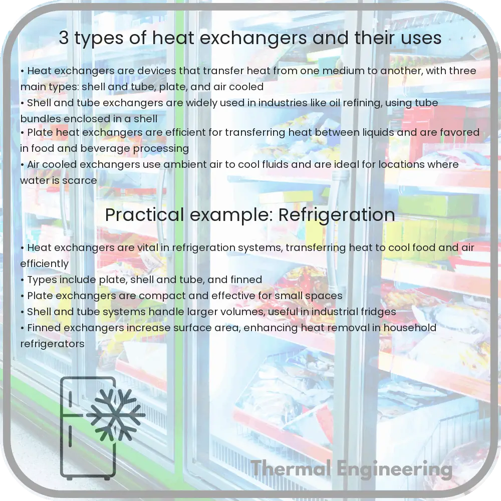
3 Types of Heat Exchangers and Their Uses

Learn about heat exchangers, essential devices for transferring heat in systems like ACs and power plants, enhancing energy efficiency and performance.

3 Types of Heat Exchangers and Their Uses

Introduction to Heat Exchangers

Heat exchangers are devices designed to transfer heat between two or more fluids—be it liquids, gases, or vapors—either by direct contact or through a separating wall. Commonly used in refrigeration, air conditioning systems, power stations, and chemical plants, these devices play a crucial role in energy efficiency and system effectiveness.

Different Types of Heat Exchangers and Their Uses

There are various types of heat exchangers designed for specific applications, efficiencies, and flow arrangements. Here, we’ll explore three fundamental types:

1. Shell and Tube Heat Exchanger

The shell and tube heat exchanger consists of a series of tubes, each of which is surrounded by a larger cylindrical shell. One fluid flows through the tubes while the second fluid flows over the tubes within the shell. This design offers high efficiency and is particularly adept at handling high-pressure applications.

  • Applications: Shell and tube heat exchangers are commonly used in oil refineries and large chemical processes where robustness and high-temperature tolerance are required.

2. Plate Heat Exchanger

Plate heat exchangers utilize thin, slightly separated plates that have very large surface areas and fluid flow passages for heat transfer. This stacked-plate arrangement can be more efficient in transferring heat than the shell and tube heat exchanger, primarily due to the larger surface area in contact with the fluid.

  • Applications: Due to their efficiency and compact size, plate heat exchangers are often used in domestic heating, solar heating applications, and in the cooling of milk and other dairy products in food processing plants.

3. Air Cooled Heat Exchanger

Also known as finned tube heat exchangers, air-cooled heat exchangers are commonly used where there is no immediate access to cooling water. They use ambient air to cool the fluid by passing it through a coil with extended outer surface area (fins).

  • Applications: These exchangers are typically used in vehicle radiators, air conditioning systems, power plants, and in process cooling under harsh environmental conditions such as in oil refineries in desert areas.

Conclusion

The choice of heat exchanger depends on a variety of factors including temperature levels, pressure, fluid states, and environmental conditions. By understanding the different types of heat exchangers and their uses, engineering solutions can be optimized for efficiency and performance in various industrial applications. While the technologies behind these devices are complex, their contribution to industrial efficiency and environmental management is invaluable, making them a critical component of modern engineering systems.

4 Types of Thermal Insulation Materials Explained

An in-depth analysis of various thermal insulation materials, their properties, applications, and factors influencing selection for energy efficiency.

4 Types of Thermal Insulation Materials Explained

Understanding Thermal Insulation Materials

Thermal insulation plays a pivotal role in reducing heat transfer between objects in thermal contact or in the range of radiative influence. It can increase energy efficiency, maintain temperature consistency, and enhance comfort in buildings and machinery. There are various types of insulation materials each suited for specific conditions and applications. Here we explore four common types of thermal insulation materials and their unique properties.

Fiberglass

Fiberglass is one of the most ubiquitous insulation materials and is composed of finely woven silicon glass fibers. This material is prized for its ability to minimize heat exchange due to its poor conductivity and the air pockets trapped between the fibers.

  • Pros: Non-flammable, lightweight, and relatively inexpensive. It also has good sound insulating properties.
  • Cons: Can irritate the skin and respiratory system during installation; hence protective gear is necessary. It can also lose effectiveness if it becomes wet.

Polystyrene

Polystyrene is a synthetic aromatic hydrocarbon polymer made from the monomer styrene. It comes in two types: expanded polystyrene (EPS), and extruded polystyrene (XPS).

  • EPS: Lighter and less expensive but has a lower R-value per inch (a measure of thermal resistance).
  • XPS: Higher density and R-value but more costly.

Both types offer excellent resistance to moisture and do not promote mold growth.

Mineral Wool

Mineral wool can refer to glass wool, which is fiberglass made from recycled glass; rock wool, made from basalt; or slag wool, made from slag from steel mills. Mineral wool is known for its superior fire resistance and sound insulation capabilities.

  • Pros: Highly fire-resistant, effective insulator and does not require additional fire retardants.
  • Cons: Can be more expensive than fiberglass and may contain higher amounts of embodied energy.

Cellulose

Cellulose insulation is derived from recycled paper products, primarily newsprint, and treated with fire retardants. It is an eco-friendly option that boasts a high R-value.

  • Pros: Excellent thermal properties and reduces air leaks more effectively than fiberglass.
  • Cons: Can settle over time, reducing its effectiveness, and may be susceptible to mold and pest infestation if not properly treated.

Choosing the Right Insulation

Selecting the right thermal insulation material depends on several factors including climate, building design, environmental impact, and budget. Energy conservation regulations and goals can also influence this choice. When installed correctly, all of these materials can significantly reduce energy bills and enhance comfort by maintaining a constant indoor temperature and minimizing the environmental footprint of heating and cooling systems.

Whether building new structures or upgrading existing ones, considering the thermal insulation material is key to achieving efficiency and effectiveness in energy use, thus contributing to overall sustainable development.

7 Types of Fluid Flow in Fluid Dynamics

An essential guide on the seven key types of fluid flow in fluid dynamics, explaining how each affects fluid behavior in engineering and physics.

7 Types of Fluid Flow in Fluid Dynamics

Introduction to Fluid Flow in Fluid Dynamics

Fluid dynamics is an essential field within physics and engineering that describes the behavior of liquids and gases in motion. Understanding how fluids flow is critical for applications ranging from designing hydraulic systems and improving the aerodynamics of vehicles to predicting weather patterns and studying blood circulation. This article outlines seven key types of fluid flow often analysed in fluid dynamics.

1. Laminar Flow

Laminar flow, often referred to as streamline flow, occurs when a fluid flows in parallel layers, with no disruption between the layers. This type of flow is characterized by smooth, constant fluid motion and typically happens at lower velocities and with higher viscosity fluids. The Reynolds number for laminar flow is typically less than 2000, providing a measure of whether flow conditions lead to laminar or turbulent flow.

2. Turbulent Flow

Unlike laminar flow, turbulent flow features chaotic changes in pressure and flow velocity. It is characterized by swirls or eddies. Turbulent flow generally occurs at higher velocities or lower viscosities and in larger pipes, with a Reynolds number greater than 4000. Predicting and managing turbulence is crucial in engineering systems such as aircraft design and pipeline transport.

3. Steady and Unsteady Flow

In steady flow, the velocity of the fluid at a given point does not change over time. Contrastingly, unsteady flow describes a situation in which the fluid’s velocity at a particular point varies with time. Most real-world situations involve unsteady flow, which requires time-dependent equations for analysis.

4. Compressible and Incompressible Flow

Fluid flow can also be classified based on the compressibility of the fluid. Incompressible flow assumes that the density of the fluid remains constant throughout its flow. This assumption simplifies analysis and is applicable in many situations dealing with liquids. Compressible flow, on the other hand, factors in variations in fluid density, which is particularly pertinent when dealing with gases at high speeds or under significant changes in pressure.

5. Uniform and Non-uniform Flow

Uniform flow occurs when the velocity of the fluid remains constant along the direction of the flow. In non-uniform flow, the velocity of the fluid changes along the flow direction. For instance, the flow velocity is usually different at different points across a river’s cross-section due to varying riverbed elevations and obstacles.

6. Viscous and Inviscid Flow

The impact of a fluid’s viscosity on its flow behavior distinguishes viscous from inviscid flow. Viscous flow accounts for the internal friction within the fluid due to its viscosity, affecting velocity profiles especially near solid boundaries. Inviscid flow, often used as an idealization, neglects viscosity for simplifying calculations. This can be practical for computations involving high-speed flows where viscosity effects are negligible in the bulk of the fluid.

7. Rotational and Irrotational Flow

In rotational flow, the fluid elements move along curved paths, with angular velocity component present. This is common in whirlpools and tornadoes. Conversely, irrotational flow pertains to situations where the fluid particles move in such a way that their rotation about their center of mass is zero. This concept is often used in potential flow theory where the viscous effects are neglected.

In summary, these seven types of fluid flow each present unique characteristics that influence the behavior of fluids under various conditions. Engineers and physicists use this knowledge to design systems and predict fluid behavior more accurately, enhancing efficiency and performance across many applications.

10 Types of Boilers in Thermal Power Plants

Learn about the various types of boilers used in thermal power plants and their impact on plant efficiency and longevity.

10 Types of Boilers in Thermal Power Plants

Overview of Boilers in Thermal Power Plants

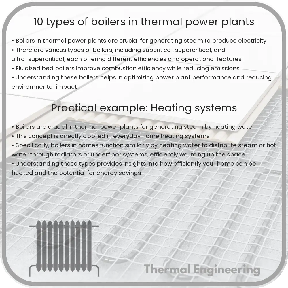
Boilers are critical components in thermal power plants that generate steam by heating water. This steam is then used to drive steam turbines which produce electricity. The efficiency, capability, and longevity of a power plant are significantly influenced by the type of boiler it employs. This article explores ten common types of boilers used in various thermal power plants around the world.

Types of Boilers Used in Thermal Power Plants

Each type of boiler has distinct characteristics and is suited to specific applications and conditions. Here, we delve into the most widely used boilers in the setting of thermal power generation.

  • Fire Tube Boiler: In fire tube boilers, the combustion gases pass inside boiler tubes, and water is circulated outside these tubes. This type is typically used in smaller plants, where space and initial costs are more critical factors.
  • Water Tube Boiler: Unlike fire tube boilers, water tube boilers circulate water inside the tubes with the hot flue gases enveloping the outside of the tubes. They can generate steam at higher pressures and are effectively used in large power plants.
  • Packaged Boiler: These boilers are usually small in size and compact, making them easy to transport and install. They are mostly used in locations where space is limited, and small capacity steam requirements.
  • Stoker Fired Boiler: These use mechanical means to feed solid fuels into the furnace and to manage the combustion process. They’re suitable for biofuels, coal, and other solid materials.
  • Pulverized Fuel Boiler: Most commonly used in large thermal power stations. These boilers burn powdered coal, achieving a higher efficiency due to the fine particle size and higher surface area for combustion.
  • Fluidized Bed Boiler: In these systems, fuel is burnt in a bed of hot, inert particles significantly enhancing the combustion efficiency. This type of boiler is effective for burning low quality fuels with high moisture content.
  • Oil and Gas Fired Boilers: These boilers are predominantly used where oil and gas are available readily and in plants where biomass and coal facilities are not viable.
  • Waste Heat Recovery Boiler: These boilers recover heat from the exhaust of turbines, industrial processes, or sometimes from the combustion of fuels. This type is particularly important in improving energy efficiency and reducing carbon footprints.
  • Circulating Fluidized Bed (CFB) Boiler: An advanced type of fluidized bed boiler, CFB boilers allow for the uniform distribution of fuel and limestone during combustion, reducing emissions of nitrogen oxides and sulfur dioxide.
  • Electric Boiler: These generate heat using electricity instead of the combustion of fuels. They are commonly used in areas with shortages of fuels and stringent emission regulations.

Choosing the Right Boiler

Choosing the appropriate boiler type for a thermal power plant depends on several factors including, but not limited to, the fuel type, the plant’s capacity, emission regulations in the area, and the available space. Engineers must evaluate both the upfront costs and the operational efficiencies when selecting a boiler for a power plant. With advancements in technology, newer types of boilers with enhanced efficiencies and lower emissions are continually being developed.

Conclusion

Understanding the different types of boilers used in thermal power plants helps in appreciating the complexity and the ingenuity of the power generation industry. It is fascinating how engineering solutions like these have evolved and adapted to meet the growing demands for energy while also considering environmental impacts.

With ongoing advancements in boiler technology, future thermal power plants are set to be more efficient, more reliable, and more environmentally friendly. The choice of boiler is pivotal in this regard, underlining the crucial role of engineering expertise in the quest for sustainable energy solutions.

Electrical Thermal Analysis

Learn how Electrical Thermal Analysis helps engineers enhance the design, efficiency, and longevity of electronic devices by managing heat generation.

Electrical Thermal Analysis

Understanding Electrical Thermal Analysis in Engineering

Electrical Thermal Analysis is a crucial aspect of engineering concerned with studying and managing the temperatures generated by electronic devices and systems. This analysis helps engineers design safer, more efficient, and longer-lasting electronic equipment by understanding how heat is produced, transferred, and dissipated within electrical systems.

Why is Electrical Thermal Analysis Important?

Every electronic component generates heat during operation. Excessive heat can lead to thermal stress, reduced reliability, and failure of electronic devices. By performing thermal analysis, engineers aim to predict and mitigate these risks, ultimately enhancing device performance and safety. This practice is particularly important in densely packed electronic devices like CPUs, GPUs, power converters, and LED lights.

The Basics of Heat Generation in Electronic Components

Heat generation in electronic devices occurs primarily due to electrical resistance and inefficiency. The power loss, which predominantly turns into heat, can be calculated using the formula:

P = I2R

Where:

  • P is the power loss (heat generation, in watts),
  • I is the current flowing through the component (in amperes),
  • R is the electrical resistance of the component (in ohms).

Other mechanisms of heat generation may include magnetic hysteresis and dielectric losses, depending on the nature of the electronic component or system.

Heat Transfer Mechanisms

In electrical thermal analysis, it is essential to understand how heat transfers from the electronic components to their environment. The three primary mechanisms of heat transfer are:

  • Conduction: Heat is transferred through materials by direct contact. This method is essential in heat sinks and thermal pads.
  • Convection: Heat is transferred through fluids (liquids or gases) that are in contact with the component. Forced air cooling with fans and liquid cooling systems are examples of convective heat transfer in electronics.
  • Radiation: Heat is transferred through electromagnetic waves and does not require any medium. It is usually less significant in standard electronic applications except at very high temperatures.

Thermal Analysis Tools and Techniques

Engineers use various tools to perform thermal analysis, including computational methods and experimental techniques. Some of the common tools and techniques include:

  • Finite Element Analysis (FEA): A numerical method that creates a detailed simulation of the physical phenomena in electronic components. It helps in understanding temperature distribution and identifying hot spots within electronic assemblies.
  • Computational Fluid Dynamics (CFD): This technique is used to analyze the flow and heat transfer in the air or cooling fluids around electronic components.
  • Infrared Thermography: A non-contact method that uses infrared cameras to visualize and measure thermal patterns and spots on the surface of electronic components.

Application of Electrical Thermal Analysis

Effective thermal management is vital across various applications—from consumer electronics like smartphones and laptops to high-power electronic systems in automotive, aerospace, and industrial equipment. By ensuring components operate within their thermal limits, electrical thermal analysis not only prolongs the life of the electronic products but also enhances their performance and reliability.

Conclusion

Electrical thermal analysis plays a fundamental role in the design and development of electronic systems. It enables engineers to evaluate how different components will respond to thermal stresses and to devise methods to control the dissipation of unwanted heat. As electronics become smaller and power densities increase, effective thermal management through comprehensive thermal analysis becomes even more essential in achieving optimal performance and longevity of electronic devices.

Whether you’re an engineer or a tech enthusiast, understanding the basics of electrical thermal analysis can provide valuable insights into the thermal considerations that go into designing and maintaining efficient electronic systems.

5 Types of Heat Transfer Methods in Thermal Engineering

Learn about the five primary methods of heat transfer in thermal engineering: conduction, convection, radiation, advection, and phase change.

5 Types of Heat Transfer Methods in Thermal Engineering

Understanding Heat Transfer: 5 Methods in Thermal Engineering

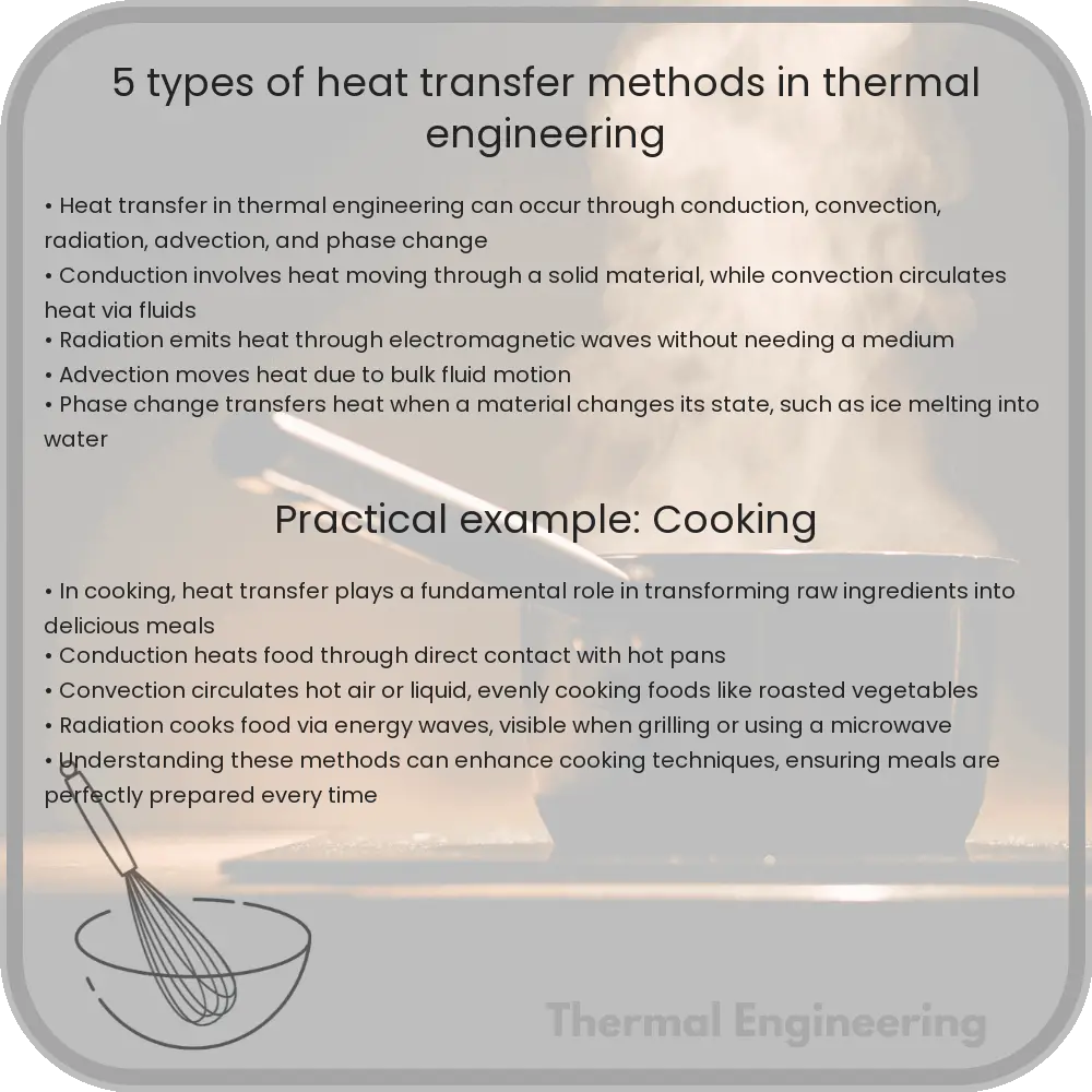
Heat transfer is a fundamental aspect of thermal engineering, playing a crucial role in various applications, from industrial manufacturing to HVAC systems in buildings. Essentially, it involves the movement of heat from one place to another, which can occur in several ways. This article delves into five primary methods of heat transfer: conduction, convection, radiation, advection, and phase change.

1. Conduction

Conduction is the process of heat transfer through a solid material from one molecule to another without any movement of the material as a whole. It occurs when a temperature gradient exists within a solid, prompting heat to flow from the warmer to the cooler regions. The rate of heat transfer by conduction can be described using Fourier’s law of heat conduction:

Q = -k * A * (dT/dx)

  • Q is the heat transfer rate (in watts, W)
  • k is the thermal conductivity of the material (in watts per meter-Kelvin, W/m∙K)
  • A is the cross-sectional area through which heat is being transferred (in square meters, m2)
  • dx is the thickness of the material (in meters, m)
  • dT is the temperature difference across the material (in Kelvin, K)

2. Convection

Convection is the transfer of heat within a fluid (gas or liquid) through the motion of the fluid itself. This motion arises from differences in fluid density, affected by temperature variations within the fluid. Convection can be categorized as either natural or forced. Natural convection results from buoyancy-driven flow; heated fluid expands, becomes less dense, and rises, whereas cooler fluid contracts and sinks. Forced convection, on the other hand, involves external forces such as fans or pumps to circulate the fluid. Convection can be quantitatively described by Newton’s law of cooling:

Q = h * A * (Ts – Tf)

  • Q is the rate of heat transfer (in watts, W)
  • h is the convective heat transfer coefficient (in watts per square meter-Kelvin, W/m2∙K)
  • A is the area through which heat is being transferred (in square meters, m2)
  • Ts is the surface temperature
  • Tf is the fluid temperature

3. Radiation

Radiation is the process by which heat is transferred in the form of electromagnetic waves. Unlike conduction and convection, radiation does not require any medium to occur. It can occur in a vacuum, as demonstrated by solar radiation reaching Earth. The amount of radiant energy emitted by a surface is given by the Stefan-Boltzmann law:

Q = ε * σ * A * T4

  • Q is the rate of heat transfer (in watts, W)
  • ε is the emissivity of the surface (dimensionless)
  • σ is the Stefan-Boltzmann constant (5.67 x 10⁻⁸ W/m2∙K4)
  • A is the area of the surface (in square meters, m2)
  • T is the absolute temperature of the surface (in Kelvin, K)

4. Advection

Advection is a type of heat transfer that often gets confused with convection. However, advection refers specifically to the transfer of heat by the large-scale movement of groups of molecules in liquids and gases. It is usually seen in meteorology, oceanography, and environmental engineering, where it plays a significant role in the distribution of heat across the earth’s surface and atmosphere.

5. Phase Change

Heat transfer during phase change is a critical aspect of thermal systems, particularly in applications involving the boiling or condensing of fluids. During a phase change, heat transfer is primarily due to the energy absorbed or released when a substance changes its state (e.g., solid to liquid, liquid to gas). This type of heat transfer is crucial in refrigeration, air conditioning systems, and boilers.

Each of these heat transfer methods has unique characteristics and is important in specific applications. Understanding how they work helps in designing efficient thermal systems for everyday applications and industrial processes.

8 Types of Fluid Dynamics Models for Engineers

Learn about essential fluid dynamics models used in engineering, including Bernoulli’s Equation, Navier-Stokes Equations, and more for effective system design.

8 Types of Fluid Dynamics Models for Engineers

Understanding Fluid Dynamics: 8 Essential Models for Engineers

Fluid dynamics is a fundamental branch of physics within the field of engineering that involves the study of fluids (liquids, gases, and plasmas) and the forces on them. It plays a crucial role in designing and optimizing various systems and devices, such as aircraft, automobiles, and HVAC systems. Here are eight key types of fluid dynamics models that engineers use to analyze fluid behavior and predict the performance of engineering systems.

1. Bernoulli’s Equation

Bernoulli’s equation is a principle of fluid dynamics that describes the conservation of energy in a flowing fluid. It states that for an incompressible, frictionless fluid, the total mechanical energy of the fluid remains constant. The equation is typically represented as:

P + 0.5 * ρ * v2 + ρgh = constant,

where P is the fluid pressure, ρ is the fluid density, v is the fluid velocity, g is the acceleration due to gravity, and h is the height above a reference point.

2. Navier-Stokes Equations

The Navier-Stokes equations, named after Claude-Louis Navier and George Gabriel Stokes, describe the motion of viscous fluid substances. These equations establish that changes in momentum in fluid particles are primarily due to viscosity, pressure, gravity, and external forces. The equations are used in complex flow modeling and are fundamental in computational fluid dynamics (CFD).

3. Euler’s Equations

Euler’s equations of fluid dynamics are a simplified version of the Navier-Stokes equations, applicable for inviscid (zero viscosity) flow. They omit the viscosity term and are useful in situations where the fluid movement is dominated by pressure and external forces rather than viscous effects.

4. Reynolds Transport Theorem (RTT)

The Reynolds transport theorem is a mathematical model used to describe the rate of change of extensive properties within a fluid system as it moves through a control volume. RTT is critical for deriving conservation equations in fluid mechanics which include conservation of mass, momentum, and energy.

5. Boundary Layer Theory

Boundary layer theory, developed by Ludwig Prandtl in the early 20th century, examines the flow behavior in the region close to a boundary, where the fluid experiences viscous forces from the surface. Understanding boundary layers is vital for predicting drag forces and designing more efficient aircraft and marine vessels.

6. Computational Fluid Dynamics (CFD)

CFD is a sophisticated approach to fluid analysis that uses numerical analysis and data structures to solve and analyze problems involving fluid flows. Engineers use CFD to simulate the interaction of liquids and gases with various surfaces. Modern CFD software includes highly detailed modeling capabilities, such as turbulence modeling, multiphase flow, heat transfer, and reactive flows.

7. Laminar and Turbulent Flow Models

Fluid flow can be classified as laminar or turbulent. Laminar flow features orderly flow layers that do not mix, while turbulent flow is characterized by chaotic, eddy-dominated movement. Engineers need to understand the nature of the flow to make predictions about flow behavior, pressure drops, and mixing efficiency.

8. Potential Flow Theory

Potential flow theory simplifies the equations of fluid dynamics and assumes an ideal, incompressible fluid with no viscosity. Although real fluids do have viscosity, potential flow theory provides valuable insights for inviscid, external flows around objects, such as the flow over aircraft wings or ship hulls.

These models are the backbone of fluid dynamics and are critical in a wide range of engineering applications. By mastering these models, engineers can better predict how fluids will behave under different conditions, leading to more innovative and effective designs.

Microcalorimetry

Learn about microcalorimetry, a technique measuring small heat amounts in physical, chemical, and biological processes, essential in scientific research and industry.

Microcalorimetry

Introduction to Microcalorimetry

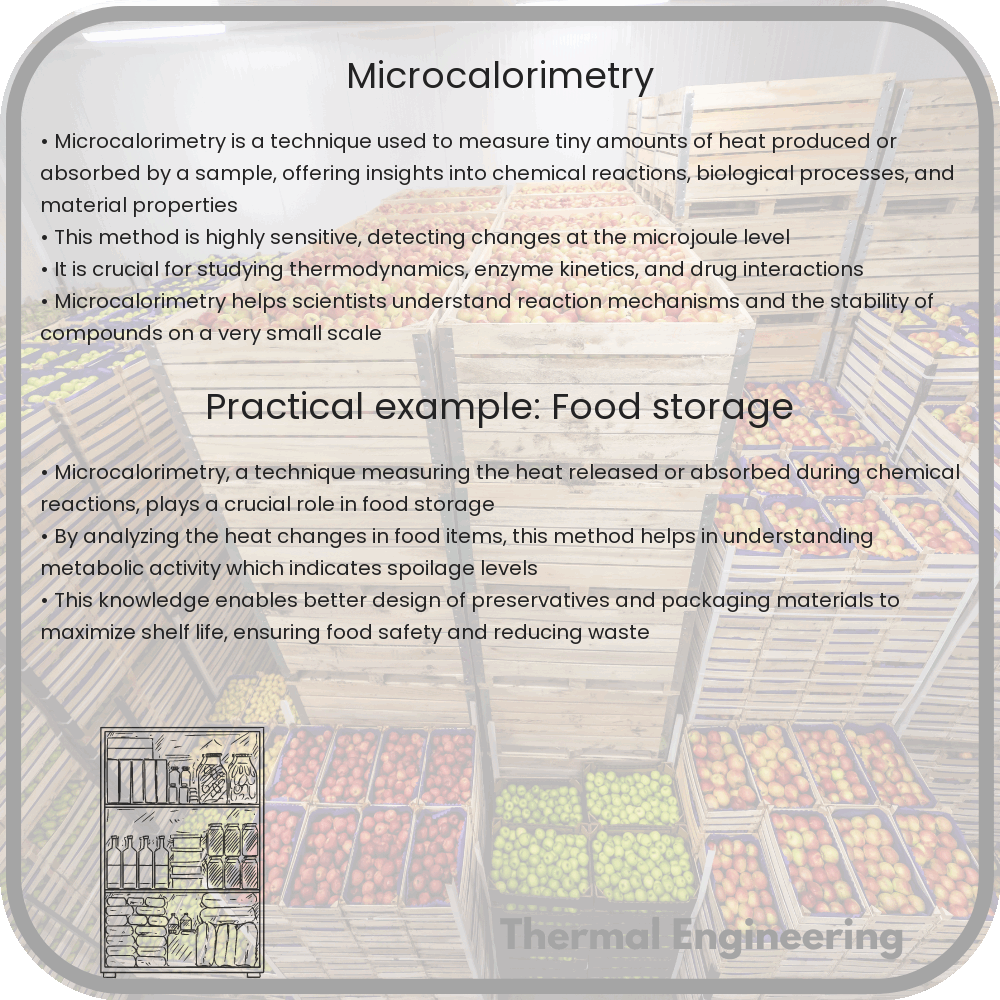
Microcalorimetry is a specialized branch of calorimetry that focuses on measuring very small amounts of heat produced or absorbed during physical processes, chemical reactions, or biological activities. This technique is pivotal in various scientific fields, including biochemistry, pharmacology, and material science, due to its sensitivity and accuracy in measuring the heat changes associated with minute samples.

Basic Principles of Microcalorimetry

At its core, microcalorimetry operates on the principle that any change in energy within a system—be it chemical, physical, or biological—can be determined by measuring heat exchange with the surroundings. In general, the relationship between heat (q) and the change in enthalpy (ΔH) can be expressed as:

\( q = \Delta H \) (at constant pressure)

This principle helps scientists understand thermodynamic properties like enthalpy changes, which are crucial for reaction feasibility and stability studies.

Types of Microcalorimeters

  • Differential Scanning Calorimeters (DSC): These devices measure how much energy is used to heat a sample versus a reference under controlled temperature conditions. DSC can analyze physical and chemical transitions, such as melting points and crystallization.
  • Isothermal Titration Calorimeters (ITC): ITC is widely used in biochemistry for studying binding interactions. It measures the heat released or absorbed when a small quantity of a reactant is titrated into a solution containing a potential binding partner.

Applications of Microcalorimetry

Microcalorimetry has a diverse range of applications across many scientific disciplines:

  • Drug Design: In pharmaceuticals, determining the binding affinity and the thermodynamics of drug interactions with targets is crucial for developing effective drugs.
  • Material Science: The technique helps in studying phase transitions, such as the crystallization and melting of polymers and other materials.
  • Environmental Science: It is used to analyze soil and sediment reactions to pollutants and the effect of microorganisms on degradation processes.

Advantages of Microcalorimetry

Microcalorimetry offers several advantages which make it an indispensable method in research:

  • Sensitivity: Capable of detecting heat changes on the order of microwatts, making it suitable for studying very small samples or weak interactions.
  • Non-destructiveness: Samples undergo minimal to no alteration during analysis, preserving them for further testing or use.
  • Versatility: Applicable to a wide range of temperatures and experimental conditions, accommodating diverse scientific inquiries.

Conclusion

Microcalorimetry is a powerful analytical tool in both research and industry, providing detailed insights into the thermodynamic characteristics of various substances and reactions. Its ability to measure minute heat changes opens up possibilities for advancements in numerous fields, contributing greatly to the development of new materials, drugs, and technologies.

Laser Flash Analysis (LFA)

Learn about Laser Flash Analysis (LFA), a technique for measuring material thermal properties essential in science and engineering.

Laser Flash Analysis (LFA)

Understanding Laser Flash Analysis (LFA)

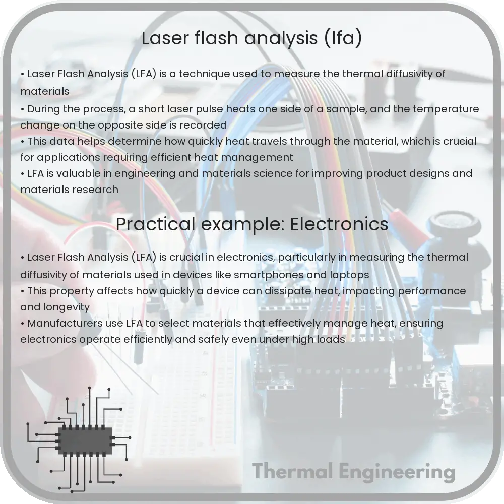
Laser Flash Analysis (LFA) is a sophisticated technique used primarily to measure the thermal diffusivity, and, with additional data, the specific heat capacity and thermal conductivity of materials. LFA plays a crucial role in the fields of material science, engineering, and thermal analysis, providing essential data for research and development, quality control, and safety testing.

How Laser Flash Analysis Works

LFA involves subjecting a small, disk-shaped sample of material to a short pulse of laser energy on one surface. The resulting temperature rise on the opposite surface of the material is then monitored using an infrared detector. The time it takes for the heat to travel through the material, known as the ‘time lag’, is precisely measured.

The fundamental relation used in LFA to determine thermal diffusivity (\(\alpha\)) is given by the formula:

\[ \alpha = \frac{{d^2}}{{\pi^2 \cdot t_{1/2}}} \]

Where:

  • \(d\) is the thickness of the sample,
  • \(t_{1/2}\) represents the time taken for the rear face temperature to reach half of its maximum value after the laser pulse.

Applications of Laser Flash Analysis

The ability of LFA to characterize thermal properties quickly and with small sample sizes makes it invaluable in several areas:

  1. Material Development: Engineers and material scientists use LFA to evaluate and compare the thermal characteristics of new materials, including metals, polymers, and ceramics.
  2. Electronic Industry: As electronics continue to shrink in size, managing heat becomes increasingly critical. LFA helps in designing materials that efficiently dissipate heat in electronic components.
  3. Aerospace and Automotive Industries: High-performance materials used in aerospace and automotive sectors are often subjected to extreme temperatures. LFA assists in understanding the thermal properties that are critical for ensuring durability and safety.

Advantages of Using Laser Flash Analysis

LFA comes with several benefits that make it a preferred method in thermal analysis:

  • Non-destructive: Being a non-contact and non-destructive testing method, LFA maintains the integrity of the sample throughout the analysis.
  • High Speed: Each measurement typically takes only a few seconds, allowing for rapid analysis and high throughput in testing.
  • Precision and Accuracy: LFA offers high precision and accuracy in measuring thermal properties, even at very high temperatures.
  • Versatility: It can be applied to a wide range of materials and temperatures, making it extremely versatile.

Limitations and Considerations

While LFA is a powerful tool, there are certain considerations and limitations that must be understood:

  • Sample Preparation: Accurate results depend heavily on the quality of sample preparation, including thickness, surface finish, and parallelism.
  • Thermal Contact Resistance: Poor contact between the sample and the temperature sensor can affect the accuracy of the data and needs to be minimized.
  • Limited to Planar Samples: LFA typically requires samples to be flat and of uniform thickness, which may not always be practical for all material types or applications.

Conclusion

Laser Flash Analysis is a critical tool in the field of thermal analysis, offering depth and precision in understanding the thermal characteristics of various materials. By enabling engineers and scientists to accurately measure thermal properties, LFA contributes significantly to material innovation and safety in numerous applications. As technology evolves, the importance of reliable and efficient thermal management is set to grow, further elevating the role of Laser Flash Analysis in modern engineering and materials science.