Facebook Instagram Youtube Twitter

Thermal Wheel | HVAC Efficiency & Heat Recovery

Learn how a thermal wheel enhances HVAC system efficiency by recovering heat and controlling humidity in buildings.
Thermal Wheel | HVAC Efficiency & Heat Recovery

Understanding the Thermal Wheel in HVAC Systems

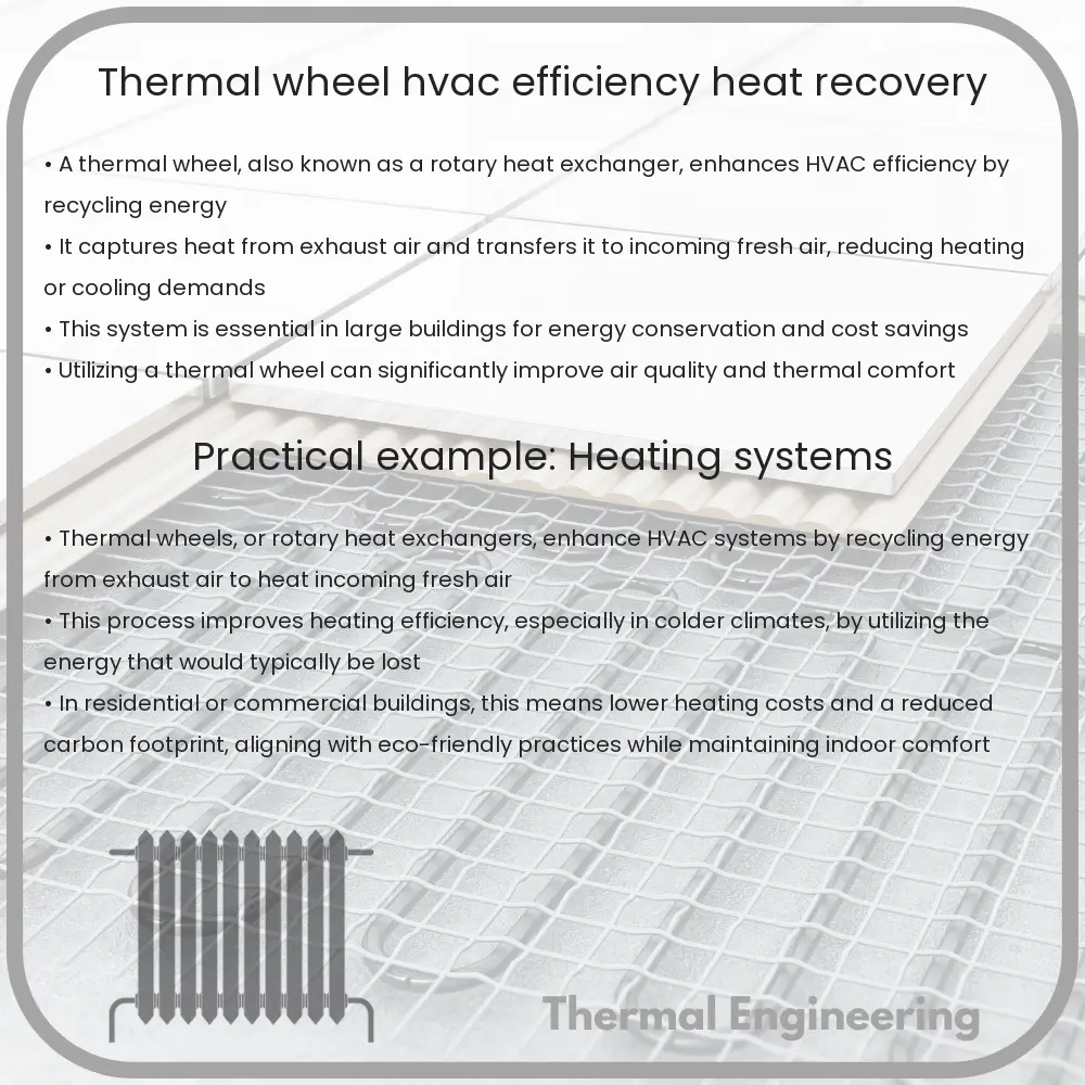
Heating, Ventilation, and Air Conditioning (HVAC) systems play a crucial role in maintaining indoor comfort in residential and commercial buildings. One of the key components that enhance HVAC efficiency is the thermal wheel, also known as a rotary heat exchanger or energy recovery wheel. This device significantly improves energy efficiency by recovering heat from exhaust air and using it to pre-condition incoming fresh air. Let’s explore how a thermal wheel works, its benefits, and its applications in HVAC systems.

How Does a Thermal Wheel Work?

A thermal wheel consists of a large, circular matrix that rotates slowly between the incoming and outgoing air streams in an HVAC system. As the wheel rotates, it absorbs heat and moisture from one air stream and transfers it to the other. This process predominantly relies on two primary physical phenomena: heat conduction and latent heat transfer.

  • Heat Conduction: As the warmer air passes by one half of the rotating wheel, the heat is conducted through the wheel material (usually metal or synthetic fiber) and is stored temporarily.
  • Latent Heat Transfer: If the air has moisture, the wheel can also absorb or desorb moisture, helping in maintaining optimal humidity levels in the conditioned space.

The effectiveness of a thermal wheel depends on several factors, including the rotational speed of the wheel, the properties of the matrix material, and the surface area available for heat exchange.

Benefits of Using a Thermal Wheel

Integrating a thermal wheel into an HVAC system brings numerous benefits:

  1. Energy Savings: By recovering heat from the exhaust air, thermal wheels reduce the demand on heating and cooling systems, leading to significant energy savings.
  2. Improved Indoor Air Quality: Since thermal wheels enable the exchange of fresh outdoor air with indoor air, they help in maintaining better air quality inside buildings.
  3. Humidity Control: The ability to transfer moisture along with heat helps in controlling the humidity levels, creating a more comfortable indoor environment.
  4. Reduced Carbon Footprint: By optimizing energy use, thermal wheels contribute to lower carbon emissions associated with heating and cooling processes.

Applications of Thermal Wheels in HVAC Systems

Thermal wheels are used in various applications across multiple industries where ventilation and air conditioning are crucial:

  • Commercial Buildings: Offices, shopping centers, and other large buildings utilize thermal wheels to enhance HVAC efficiency and comfort for occupants.
  • Industrial Facilities: Factories and warehouses with high thermal loads benefit from the heat recovery capabilities of thermal wheels, maintaining better control over temperature and air quality.
  • Residential Complexes: Multi-unit residential buildings also use thermal wheels to improve energy efficiency while ensuring sufficient ventilation.

Challenges and Considerations

Despite their benefits, thermal wheels do have some challenges that need careful consideration:

  • Cross-contamination: If not properly maintained, there is a risk of contaminant transfer between the exhaust and intake air streams.
  • Maintenance Requirements: Regular cleaning and maintenance are necessary to preserve the efficiency and longevity of the wheel.
  • Initial Cost: The upfront cost for integrating a thermal wheel into an existing system can be significant, though it is often offset by the operational savings.

In conclusion, the thermal wheel is a pivotal component in modern HVAC systems, providing substantial energy savings and comfort enhancements. As technology progresses, further improvements in material science and control strategies are expected to increase the effectiveness and applications of thermal wheels in energy recovery and HVAC efficiency.
Variable Frequency Drive | Motor Speed & Energy Savings

Learn how Variable Frequency Drives (VFDs) optimize motor control by adjusting frequency and voltage, leading to significant energy savings and enhanced operational efficiency in industrial settings.

Variable Frequency Drive | Motor Speed & Energy Savings

Understanding Variable Frequency Drives

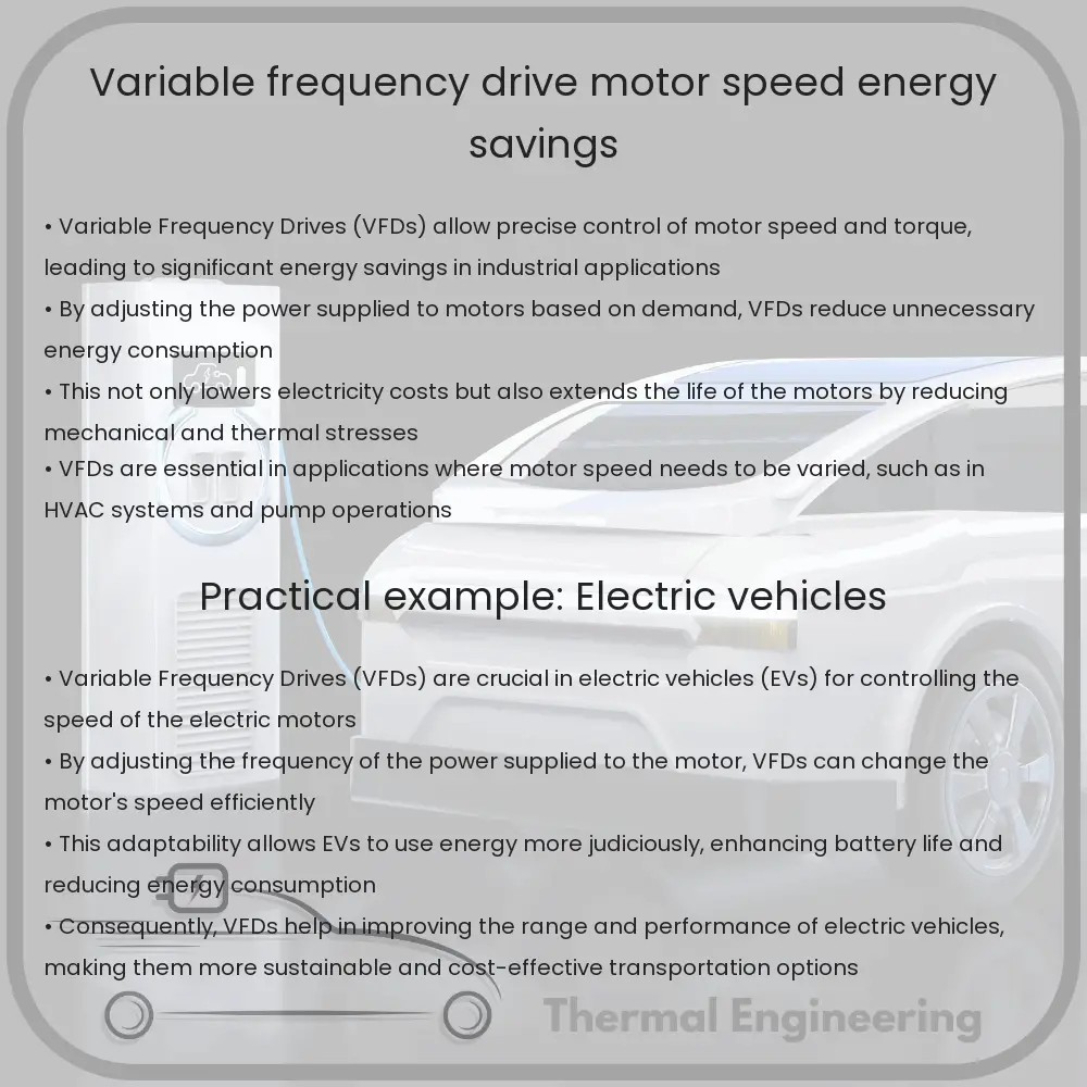
A Variable Frequency Drive (VFD) is a type of motor controller that drives an electric motor by varying the frequency and voltage supplied to the electric motor. This ability to control the power input to the motor allows for significant energy savings as well as better control of motor operation. VFDs are widely used in industrial applications to enhance system efficiency and extend the life of mechanical components.

How Variable Frequency Drives Work

VFDs mainly include three components: the rectifier, which converts the incoming alternating current (AC) to direct current (DC); the DC bus, which stores the DC power; and the inverter, which converts the DC back into AC with the desired frequency. By adjusting the frequency of the AC power output, the drive can control the motor speed, since the speed of AC motors is primarily determined by the frequency of the AC supply.

Motor Speed Control

The primary function of a VFD is to control the speed of an electric motor. The speed of an AC motor is given by the equation:

Speed (RPM) = (120 * Frequency) / Number of Poles

Where “Frequency” is the frequency of the AC power supplied (in Hertz), and “Number of Poles” is the number of poles the motor is constructed with. By changing the frequency, the VFD can increase or decrease the motor speed, which is essential for applications requiring different speeds for various processes.

Energy Savings

One of the significant advantages of using a VFD is the potential for energy savings. In many applications, machinery does not need to operate at full speed at all times. By using a VFD to slow down the motor during lower demand periods, energy consumption is reduced. The power required to run a motor decreases as the cube of the motor’s speed; this relationship is modeled by the equation:

Power = Torque * (Speed3)

Therefore, small reductions in speed can lead to significant reductions in energy usage, highlighting the efficiency benefit of using VFDs.

Other Benefits of Variable Frequency Drives

  • Extended Equipment Life: By controlling the acceleration and deceleration of electric motors, VFDs reduce the mechanical stress on motors and connected equipment, resulting in extended operational life.
  • Reduced Motor Maintenance: Slower operating speeds can lead to longer intervals between maintenance, reduced wear and tear, and lower repair costs.
  • Improved Process Control: VFDs offer precise speed control which is crucial for many manufacturing processes where precision and repeatability are key.

Conclusion

The utilization of Variable Frequency Drives in modern engineering is a testament to how advances in technology can be employed to create more efficient and effective operating environments. By controlling motor speed and reducing energy consumption, VFDs not only offer cost savings but also contribute to the sustainability and operational efficiency of industrial applications.

Gate Valve | Pipeline Isolation & Low Friction

Learn about gate valves, essential for efficient fluid control and pipeline isolation in various industrial applications.

Gate Valve | Pipeline Isolation & Low Friction

Understanding Gate Valves: Ensuring Efficient Pipeline Isolation with Low Friction

Gate valves are a crucial component in pipeline systems, used widely to control the flow of various types of fluids in industrial, commercial, and residential applications. These valves function primarily as isolation devices, designed to either completely stop or allow fluid flow. Their ability to minimize friction loss when fully open makes them particularly beneficial in systems requiring unobstructed flow.

Functionality and Design

A gate valve operates using a simple mechanism: a flat closure element known as a “gate” moves up and down to control the fluid flow. The gate is usually a rectangular or wedge-shaped disc which, when lifted, aligns with the direction of the flow, allowing fluid to pass. When the gate is lowered, it seats tightly within a valve body, blocking the flow path and creating a seal.

  • Open Position: In the open position, the gate is completely retracted into the valve bonnet, offering minimal resistance to flow. This position is ideal for applications where full flow efficiency is necessary.
  • Closed Position: In the closed position, the gate fully obstructs the flow path. The valve design ensures that there is a tight seal, preventing any leakage across the valve.

Advantages of Gate Valves

  1. Minimal Pressure Drop: When fully open, gate valves exhibit no obstruction in the flow path, resulting in a very low friction loss and thus maintaining the system’s pressure integrity.
  2. Better Sealing: The design of gate valves allows for a tight seal, making them effective for use in applications requiring a reliable isolation method.
  3. Durability: Due to their simple design and few moving parts, gate valves are generally more durable and have a longer service life compared to other types of valves.

Applications

Gate valves are extensively used across various sectors due to their effective isolation capabilities and efficiency in maintaining full flow conditions:

  • Water and Wastewater Management: They are commonly used in large scale water distribution systems, such as water treatment plants and irrigation systems.
  • Oil and Gas Industries: Gate valves are suited for high-pressure environments and are used in both upstream and downstream activities.
  • Manufacturing: These valves are used in manufacturing processes that involve large volumes of liquids, including chemicals, where precise flow control is not a priority but isolation is crucial.

Maintenance and Limitations

While gate valves are advantageous in many scenarios, they require regular maintenance to perform optimally, and they have certain limitations:

  • Maintenance: The simplicity of gate valves can be a drawback if sediment builds up within the valve, potentially causing the gate to stick. Regular maintenance and occasional cleaning are necessary to ensure smooth operation.
  • Not for Throttling: Gate valves are not designed to regulate flow gradually. Frequent operation between the open and closed positions can cause damage to the gate and valve seats, leading to leaks.

Understanding the operation and characteristics of gate valves can help in selecting the right type of valve for specific applications, ensuring both efficiency and longevity of the pipeline system.

Submersible Pump | Efficiency in Water Extraction

Learn about submersible pumps, their design, efficiency factors, and advantages in water extraction technology.

Submersible Pump | Efficiency in Water Extraction

Understanding Submersible Pumps: Enhancing Efficiency in Water Extraction

Submersible pumps are highly efficient tools used for extracting water from deep underground sources. These pumps, which are completely submerged in liquid, are crucial in various applications such as irrigation, water supply for residential and industrial sectors, and dewatering. The unique design and operation of submersible pumps provide significant advantages in terms of efficiency and functionality.

The Design of Submersible Pumps

A submersible pump typically consists of a tightly sealed motor close-coupled to the pump body. The entire assembly is submerged in the fluid to be pumped, which prevents pump cavitation, an issue associated with a high elevation difference between pump and the fluid surface. Submersible pumps push water to the surface, unlike jet pumps which create a vacuum and rely on atmospheric pressure. This design attribute leads to a more efficient pumping process with reduced energy consumption.

Factors Influencing the Efficiency of Submersible Pumps

  • Motor Efficiency: The motor’s efficiency plays a critical role in the overall energy consumption of submersible pumps. Advances in motor technology and materials have led to higher efficiency rates, which in turn reduce operational costs.
  • Impeller Design: The impeller, often a critical component of submersible pumps, directly impacts their performance. Improved impeller designs enhance the flow mechanics and minimize hydraulic losses, thereby improving the efficiency.
  • Hydraulic Efficiency: This is determined by the pump’s ability to convert mechanical energy into hydraulic energy without excessive friction or turbulence. Pumps designed with optimal hydraulic pathways and minimal internal resistance yield higher efficiencies.

Advantages of Using Submersible Pumps

  • Reduced Energy Consumption: By being placed within the fluid, submersible pumps require less energy to pump water, unlike external pumps which need additional energy to draw water into the pump system.
  • Low Maintenance: The sealed unit design prevents pump leakage and minimizes maintenance requirements. This makes submersible pumps a cost-effective solution in the long term.
  • Quiet Operation: As the pumps are submerged, they operate more quietly than surface pumps, reducing noise pollution.

Efficiency Metrics and Performance Evaluation

To evaluate the efficiency of a submersible pump, several performance metrics can be assessed:

  1. Total Dynamic Head (TDH): It measures the total equivalent height that a fluid is to be pumped, considering friction losses in the pipe.
  2. Flow Rate: The volume of fluid that can be pumped per unit of time, typically measured in gallons per minute (GPM) or cubic meters per hour.
  3. Energy Efficiency Ratio (EER): It evaluates the amount of work the pump can perform for each unit of power consumed, analogous to the efficiency ratings used for electrical appliances.

To maximize efficiency, it’s essential to choose the right pump size and specifications based on the application’s specific needs and the nature of the liquid being pumped. Regular maintenance and checks are imperative to sustain high operational efficiency and prolong the lifespan of submersible pumps.

Conclusion

Submersible pumps are a steadfast technology that offers both reliable and efficient solutions for water extraction. Their design and operational mechanics cater to a plethora of needs while also respecting energy conservation. With continuous advancements in this technology, the future for efficient water management through submersible pumps looks promising.

Air Separator | Efficiency in Hydronic Systems

Learn how air separators in hydronic systems enhance efficiency by eliminating air, reducing noise, and preventing corrosion.

Air Separator | Efficiency in Hydronic Systems

Understanding Air Separators in Hydronic Systems

Air separators are crucial components in hydronic heating and cooling systems, which use water to transfer heat. Understanding how air separators enhance system efficiency is vital for optimizing performance and longevity of these systems. This article explores the role of air separators, how they function, and their impact on the efficiency of hydronic systems.

Role of Air Separators

The primary role of an air separator is to remove air and gases from the heating or cooling fluid. Air can enter a hydronic system during filling or through micro-leaks when the system is operational. Air presence in a hydronic system can lead to several issues including:

  • Corrosion of metal components due to oxygen dissolution.
  • Reduced heat transfer efficiency as air acts as an insulator.
  • Noise generation, commonly known as ‘knocking’, in the pipeline.
  • Flow blockages and system malfunction.

By effectively removing air, air separators help in maintaining the integrity and efficiency of the system.

Types of Air Separators

There are primarily two types of air separators used in hydronic systems:

  1. Centrifugal Air Separators: These utilize the centrifugal force generated by the moving fluid to separate air from the water. The air collects at the center and is purged from the system.
  2. Coalescing Air Separators: These are designed to force small air bubbles to join together into larger bubbles, which rise to the top of the separator and are then vented out.

Choosing the appropriate type depends on factors like system size, flow rate, and specific system requirements.

How Air Separators Enhance System Efficiency

Efficiency in hydronic systems is broadly governed by how effectively they can transfer heat and how smoothly fluid flows through the system. Air separators improve efficiency in several ways:

  • Preventing Heat Transfer Loss: By removing air from the system, air separators prevent the formation of air pockets that can significantly reduce heat transfer capabilities of the heat emitter.
  • Reducing Energy Consumption: Eliminating air reduces the risk of clogging and flow resistance. This means pumps can operate at lower pressures, reducing the power consumption.
  • Enhancing Component Lifespan: Since air can cause corrosion and wear, removing air helps in prolonging the lifespan of system components.

Measuring Efficiency of Air Separators

The efficiency of an air separator in a hydronic system can be measured by its ability to maintain an air-free system. The performance is often indicated by the reduction in maintenance calls, increased system reliability, and lower operational costs. Monitoring tools and system feedback can aid in assessing the effectiveness of an air separator.

In conclusion, air separators are an indispensable component in hydronic systems. Their ability to efficiently remove air not only enhances the system’s operational efficiency but also contributes to the longevity and reliability of the system. Proper selection, installation, and maintenance of air separators are crucial to fully realize these benefits.

Condenser | HVAC Efficiency & Steam Condensation

Explore the vital role of condensers in HVAC systems and steam power plants, focusing on their types, operation, and impact on system efficiency.

Condenser | HVAC Efficiency & Steam Condensation

Understanding the Role of Condensers in HVAC Efficiency and Steam Condensation

A condenser is a critical component in various engineering systems, notably in heating, ventilation, and air conditioning (HVAC) systems as well as in steam power plants. Despite their widespread use, the principles behind condensers and their impact on system efficiency often go unnoticed. This article delves into the operation of condensers, their types, and their pivotal role in enhancing the efficiency of systems.

What is a Condenser?

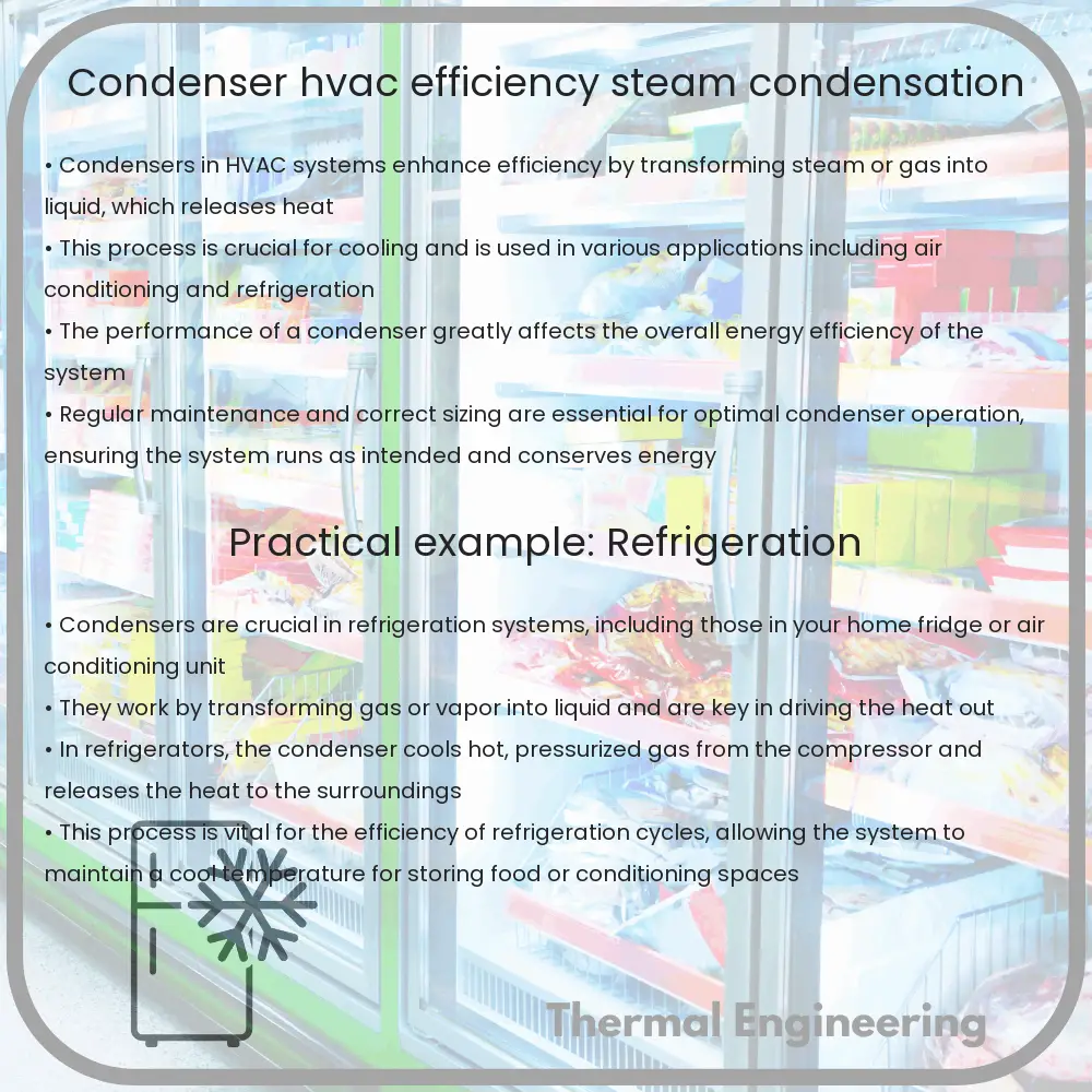
In the most general sense, a condenser is a device or unit used to condense a substance from its gaseous to its liquid state, typically by cooling it. In doing so, the latent heat is released by the substance and transferred to the surrounding environment.

Types of Condensers

  • Air-Cooled Condensers: These condensers expel heat into the atmosphere directly using fans or natural convection.
  • Water-Cooled Condensers: These systems use water to remove the latent heat from the condenser coils and are typically more efficient than air-cooled versions.
  • Evaporative Condensers: These combine wet and dry cooling by allowing some of the fluid to evaporate into the atmosphere, aiding in the heat removal process.

Condensers in HVAC Systems

In HVAC systems, condensers are used in the heat rejection process. For air conditioners, the condenser is part of the outdoor unit where refrigerant gas is compressed and forced through condenser coils, where it is cooled and turned back into a liquid. The efficiency of an air conditioner or heat pump is significantly dependent on the performance of the condenser. Factors influencing the efficiency include the type and size of the condenser, ambient temperature, and maintenance level.

Condensers in Steam Power Plants

Steam power plants use condensers to condense exhaust steam from steam turbines. The process is crucial for improving the efficiency of turbines by maintaining a low backpressure on the exhaust side. Commonly, water-cooled condensers are used in this setting to handle large volumes of steam.

The thermal efficiency of steam power plants is significantly impacted by the performance of these condensers. The general formula for calculating the efficiency (\(\eta\)) is given by:

\(\eta = 1 – \frac{T_c}{T_h}\)

Here, \(T_c\) represents the cool reservoir temperature (condenser temperature), and \(T_h\) is the hot reservoir temperature (boiler temperature).

Improving HVAC and Plant Efficiency Through Effective Condensation

Maintaining an effective condenser is key to optimizing the efficiency in both HVAC systems and steam power plants. This is achieved through:

  • Regular cleaning of condenser coils to ensure unimpeded heat transfer.
  • Ensuring adequate air flow around the condenser unit to avoid recirculation of hot air.
  • Using water treatment in water-cooled condensers to prevent scaling and corrosion, which impair heat transfer efficiency.

Ultimately, condensers play a fundamental role in the process of heat exchange necessary for efficient system operations across different applications. By understanding their function and maintaining them properly, significant improvements in system efficiency can be achieved, leading to cost savings and reduced environmental impact.

Fluid Coupling | Smooth Automotive Starts

Learn how fluid coupling facilitates smooth automotive starts, reduces wear, and enhances vehicle efficiency.

Fluid Coupling | Smooth Automotive Starts

Understanding Fluid Coupling for Smooth Automotive Starts

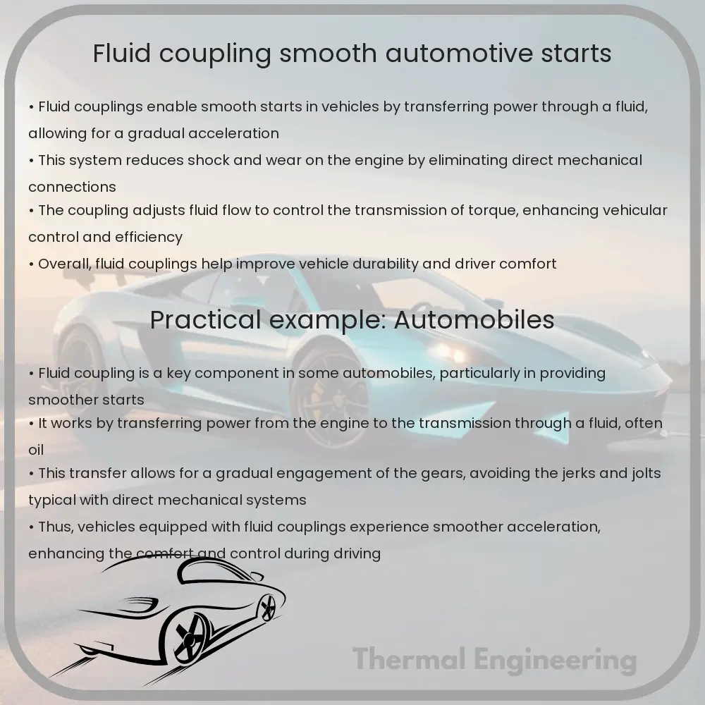
Fluid coupling is an integral component used in automotive powertrains to facilitate smooth and controlled transfer of power from the engine to the transmission system. Unlike hard couplings, fluid couplings allow for a slip between the input and output connections, which provides a range of benefits including reduced wear on components and smoother vehicle starts.

How Fluid Couplings Work

At its core, a fluid coupling consists of two primary parts: the pump (or impeller) and the turbine. Both components are shaped like shells and are filled with hydraulic fluid. The impeller is connected to the engine (input) and as it rotates, it propels the hydraulic fluid centrifugally. This accelerated fluid impacts the blades of the turbine (output), which is connected to the transmission. The motion and energy of the fluid are thus converted back into rotational motion by the turbine, completing the power transmission process.

  • Slip Characteristic: One of the defining features of a fluid coupling is its ability to ‘slip’. Unlike a mechanical clutch, there is always a certain amount of RPM difference between the impeller and the turbine, which can be advantageous during gradual start or variable load conditions.
  • Smooth Acceleration: The slip also allows for smoother acceleration, as it absorbs shocks and vibrations between the moving parts. This is especially beneficial in preventing jerks and enhancing ride comfort during the initial acceleration from a standstill.
  • Torque Conversion: Fluid couplings can also adapt to varying torque demands, which aids in efficient vehicle performance across different speeds and load conditions. The fluid dynamics within the coupling adjust naturally, offering greater control over the torque output.

Advantages of Using Fluid Coupling in Vehicles

  1. Protective to Drive System: By mitigating mechanical shocks during torque transfer, the fluid coupling extends the lifespan of gearbox and other drivetrain components.
  2. Reduction in Maintenance Costs: The wear and tear on parts are reduced, leading to lower maintenance and repair costs.
  3. Increased Fuel Efficiency: Through more efficient power transfer and the ability to adapt to varying load conditions, fluid couplings can contribute to better fuel economy in some cases.
  4. Enhanced Driver Comfort: The smoothing effect on power transmission greatly enhances driving comfort, a crucial factor in commercial and public transportation vehicles.

Applications Beyond Automotive

While prevalent in the automotive industry, fluid couplings are also widely used in other areas such as marine, industrial, and railway engines. Their ability to handle high inertial loads and provide controlled start-up without shock loading makes them ideal for heavy machinery and applications requiring precise speed control and load management.

Fluid couplings depict a fascinating application of fluid dynamics in power transmission. By enabling smoother starts and offering protection against mechanical wear, these devices play a crucial role in enhancing vehicle performance and lifespan.

In conclusion, the integration of fluid couplings in automotive engineering not only aids in smooth vehicular starts but also contributes to overall system durability and efficiency. As vehicle technology evolves, the role of components like fluid couplings remains pivotal in meeting the increasingly stringent performance and efficiency standards.

Thermal analysis software tools

Explore the essential roles and capabilities of thermal analysis software tools in engineering for optimizing design and performance efficiency.

Thermal analysis software tools

Introduction to Thermal Analysis Software Tools

Thermal analysis software tools are essential in the field of engineering for evaluating and predicting the thermal performance of materials and systems. These tools use numerical methods to simulate heat transfer processes including conduction, convection, and radiation within and between objects. Engineers use these tools across various industries including aerospace, automotive, electronics, and construction to optimize design, enhance safety, and improve efficiency.

Key Functions of Thermal Analysis Software

Thermal analysis software performs a variety of functions that help engineers in understanding how objects will perform under different thermal conditions:

  • Temperature Distribution: Calculate the temperature distribution within a component or assembly over time.
  • Thermal Stresses: Predict thermal stresses that occur due to temperature gradients, phase changes, or thermal expansion.
  • Heat Transfer Analysis: Analyze various modes of heat transfer such as conduction, convection, and radiation.
  • Transient Analysis: Study how thermal responses change over time as conditions change.
  • Optimization: Help in the optimization of thermal characteristics to improve design and performance.

Popular Thermal Analysis Software Tools

There are several leading software tools specifically tailored for thermal analysis, notable among them are:

  • ANSYS Fluent: Widely used for its robust capabilities in modeling fluid dynamics and thermal analysis, including detailed heat transfer mechanisms.
  • SolidWorks Simulation: Offers a user-friendly interface with powerful tools for conducting thermal analysis as part of a broader set of simulation features.
  • Autodesk CFD: Known for its capabilities in computational fluid dynamics (CFD), it also provides detailed thermal analysis options especially useful in architectural and product design contexts.
  • COMSOL Multiphysics: A versatile tool that allows for coupled or multiphysics scenarios where thermal interactions with other physical phenomena are crucial.

Applications in Engineering

The applications of thermal analysis software in engineering are vast and varied:

  • Aerospace: Ensuring thermal comfort within spacecraft and predicting thermal stresses on spacecraft components caused by extreme temperatures of space.
  • Automotive: Improving engine thermodynamics, brake heating analysis, and overall vehicular thermal management.
  • Electronics: Preventing overheating in devices like smartphones and computers, and ensuring heat dissipation components are effectively designed.
  • Construction: Analyzing heat transfer through buildings to enhance energy efficiency and occupant comfort.

Future of Thermal Analysis Software

Advancements in computing power and algorithms are making thermal analysis software increasingly accurate and faster. In the future, integration with AI and machine learning could further revolutionize how thermal analysis is performed, leading to even more optimized and efficient designs, and potentially new materials with tailored thermal properties.

Conclusion

Thermal analysis software is an indispensable tool in modern engineering that aids in making informed decisions about design and materials. By predicting thermal behavior, engineers can ensure reliability, efficiency, and safety of their projects, ultimately leading to innovative solutions and sustainable practices.

Refrigeration Compressor | Types & Cooling Efficiency

Learn about refrigeration compressors, their types like reciprocating, rotary, and centrifugal, and how they influence cooling efficiency.

Refrigeration Compressor | Types & Cooling Efficiency

Understanding Refrigeration Compressors: Types and Cooling Efficiency

Refrigeration compressors are crucial components in refrigeration and air conditioning systems, pumping refrigerant through the cycle to remove heat and provide cooling. Their design and operational efficiency play a vital role in the overall efficiency and energy consumption of cooling systems. In this article, we will explore the different types of refrigeration compressors and how their design impacts cooling efficiency.

Types of Refrigeration Compressors

There are several types of compressors used in refrigeration systems, each with unique characteristics and applications. Here’s a closer look at the most common types:

  1. Reciprocating Compressors: These compressors use pistons driven by a crankshaft to compress the refrigerant. Known for their high efficiency and capability to work at high pressures, reciprocating compressors are commonly used in both residential and commercial units.
  2. Rotary Compressors: Rotary compressors utilize rotors to compress the refrigerant. They are divided into several types, including screw, scroll, and vane compressors. Rotary compressors are generally compact and smooth running with lower noise levels, making them a popular choice for residential air conditioning systems.
  3. Centrifugal Compressors: These are typically used in large industrial applications and work by using a rotating impeller to transfer kinetic energy to the refrigerant. Centrifugal compressors operate best at high capacities and are favored for their minimal maintenance needs and durability.

Cooling Efficiency in Refrigeration Compressors

Cooling efficiency of refrigeration compressors is determined by several factors including the compressor type, refrigerant used, and system design. The efficiency is often measured by the Energy Efficiency Ratio (EER) or Seasonal Energy Efficiency Ratio (SEER) which are ratios of the cooling capacity to the power input. Higher ratios indicate better efficiency.

  • Design Features: Advanced design features such as variable speed drives and digital controls allow compressors to adjust their output based on cooling demand, significantly improving energy efficiency.
  • Maintenance: Regular maintenance is essential to ensure that compressors are running efficiently. This includes checking for leaks, ensuring the refrigerant charge is correct, and verifying that the system controls and sensors are functioning properly.
  • Refrigerant Type: The type of refrigerant can also affect the compressor’s efficiency. Newer refrigerants often aim to offer better cooling performance and reduced environmental impact.

Understanding the types of refrigeration compressors and their efficiency contributes to better selection and maintenance of these systems, leading to reduced energy usage and operational costs. With continuing advancements in technology, compressors are becoming even more energy-efficient, aligning with global energy standards and sustainability goals.

Conclusion

Refrigeration compressors are essential for cooling systems in a wide range of applications. The choice between reciprocating, rotary, and centrifugal compressors will depend on specific needs regarding efficiency, noise, capacity, and maintenance. By optimizing compressor type and maintenance practices, it’s possible to enhance system efficiency and sustainability while cutting costs.

Flow Nozzle | High Velocity & Steam Applications

Learn about flow nozzles, crucial tools for managing high-velocity fluid and steam flow in various engineering applications, ensuring precise control and measurement.

Flow Nozzle | High Velocity & Steam Applications

Understanding the Role of Flow Nozzles in High Velocity and Steam Applications

Flow nozzles play a critical role in various engineering fields, where the accurate measurement and management of high-velocity fluid and steam flow are essential. A flow nozzle is a device designed to provide precise control over flow conditions in pipes or channels, particularly in environments where the flow is too high-speed or the fluids are susceptible to high temperatures and pressures.

Design and Operation

A flow nozzle is typically shaped like a venturi tube with a sharp entrance and a divergent exit. It is inserted into a pipeline to cause a restriction that accelerates the fluid through a narrow throat section, leading to a pressure drop. This design enables the measurement of flow rates by relating the pressure difference between the upstream side and the throat to the velocity of the fluid.

Equations and Calculations

The fundamental principle used for calculating flow rate through a flow nozzle is based on Bernoulli’s Equation and the Continuity Equation. Bernoulli’s Equation is expressed as:

P1 + 0.5 * ρ * v12 = P2 + 0.5 * ρ * v22

where:

  • P1 and P2 are the pressures before and at the nozzle throat, respectively,
  • v1 and v2 are the fluid velocities before and at the nozzle throat, respectively,
  • ρ is the density of the fluid.

The Continuity Equation can be stated as:

A1 * v1 = A2 * v2

where:

  • A1 and A2 are the cross-sectional areas of the pipe before and at the nozzle throat, respectively.

Combining these principles, the flow rate (Q) can be calculated using the expression:

Q = A2 * sqrt((2 * (P1 – P2) / ρ) / (1 – (A2/A1)2))

Applications in High Velocity and Steam

Flow nozzles are especially advantageous in high-velocity applications, including steam, gas, and air flow measurements in power plants, refineries, and chemical plants. Their ability to handle high-pressure drops without significant energy losses makes them ideal for steam flow measurement, where traditional flow meters might fail due to the severe environment.

Advantages and Limitations

The major advantages of flow nozzles include:

  • High durability and minimal maintenance needs due to the lack of moving parts,
  • Capability to handle large flow rates and high pressures,
  • Relatively easy installation and calibration compared to other flow meters.

However, flow nozzles also have some limitations:

  • Susceptibility to wear and erosion, particularly at the throat, due to high-velocity flows,
  • Potential for blockages from solid particles carried in the fluid stream,
  • Necessity for straight pipe sections upstream and downstream to reduce turbulence affecting measurements.

Conclusion

Flow nozzles are essential tools in engineering applications that involve high-velocity fluids and steam. By understanding their design, operation, and the basic principles underlying their use, engineers can effectively utilize flow nozzles to improve system efficiency and reliability across a variety of industrial applications.