Facebook Instagram Youtube Twitter

Pressure Relief Valve | Safety & Overpressure Protection

Learn how Pressure Relief Valves (PRVs) function as critical safety devices in engineering systems to prevent overpressure and ensure safety.
Pressure Relief Valve | Safety & Overpressure Protection

Understanding Pressure Relief Valves: Ensuring Safety and Overpressure Protection

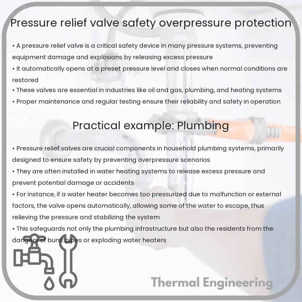
Pressure relief valves (PRVs) are critical safety devices in engineering systems where pressure can build up and exceed the design limits of the system components. These valves play an essential role in protecting equipment, preventing catastrophic failures, and ensuring the safety of personnel. The basic function of a PRV is to automatically release pressure from a boiler, pressure vessel, or other system when the pressure or temperature exceeds preset limits.

How Pressure Relief Valves Work

The operation of pressure relief valves involves a mechanical setup where the valve is typically kept closed by a spring or other mechanical force. The force exerted by the spring is calibrated against the maximum allowable working pressure (MAWP) of the system. When the system pressure exceeds this set limit, the force of the pressure overcoming the spring opens the valve, allowing the excess gas or fluid to escape, thereby relieving the pressure.

Types of Pressure Relief Valves

  • Safety Valves: Often used in gas or vapor systems such as steam boilers, safety valves are designed to open rapidly (pop action) and fully at a set pressure.
  • Relief Valves: More commonly used in liquid systems, these valves open gradually, allowing the fluid to escape as the pressure increases beyond the threshold.
  • Safety Relief Valves: These are versatile valves capable of functioning in both liquid and gas systems, providing the features of both safety and relief valves.

Key Components and Features

  • Set Pressure: The predetermined pressure at which the PRV will start to open to release pressure.
  • Overpressure: The percentage of increase in pressure above the set pressure; typically, systems are designed to handle a certain level of overpressure (e.g., 10% above MAWP).
  • Blowdown: The difference between the pressure at which the valve opens and the pressure at which it reseats or closes, ensures that the valve does not frequently open and close around the set point.

Material and Design Considerations

The design and manufacturing materials of pressure relief valves are critical factors that affect their reliability and effectiveness. Common materials include brass, bronze, and stainless steel, each chosen based on the application, chemical compatibility, and required strength. Design considerations often involve temperature handling capability, corrosion resistance, and the physical properties of the fluids involved.

Sizing and Installation

Sizing a pressure relief valve correctly is crucial to its performance. An undersized valve might not be able to effectively discharge pressure quickly enough, leading to potential system failures. Conversely, an oversized valve could lead to improper sealing and frequent leakage. Installation involves strategic placement where the valve is most effective, typically at high points or near pressure sources in a system. Installation also requires regular maintenance and testing to confirm that the valve operates correctly.

Applications and Importance

Pressure relief valves find applications across a wide range of industries, including oil and gas, pharmaceuticals, and manufacturing, where they help manage the systems’ internal pressures. In domestic environments, they are used in water heating systems, where they prevent potential overpressure caused by thermal expansion.

The importance of PRVs cannot be overstated, as these valves directly contribute to the operational safety and efficiency of many industrial and residential systems. By understanding their functionality, types, and proper maintenance routines, users can significantly mitigate the risks associated with overpressure.

Overall, pressure relief valves serve as a fundamental safeguard, highlighting the intricate balance between operational efficiency and safety in engineering systems.
Cooling Jacket | Engine & Equipment Cooling

Learn how cooling jackets prevent overheating in engines and equipment by improving efficiency and durability through advanced materials and design.

Cooling Jacket | Engine & Equipment Cooling

Understanding Cooling Jackets in Engine & Equipment Cooling

Cooling jackets are a critical component used in the cooling systems of internal combustion engines and various industrial machinery. They are designed to manage the temperature of the engine and prevent overheating, ensuring the machinery runs efficiently and safely. Let’s explore how cooling jackets work, their importance, and the different materials used in their construction.

How Does a Cooling Jacket Work?

A cooling jacket is typically integrated around or within an engine block or other equipment components that generate significant heat. The primary function of a cooling jacket is to transfer heat away from the engine parts to avoid damage or failure due to high temperatures.

The process involves the circulation of a coolant — usually water or a glycol mixture — through channels that surround the heat-generating parts of the engine. As the coolant moves through the jacket, it absorbs the excess heat. This heated coolant then travels to a radiator where it is cooled by air flow before recirculating back into the cooling jacket. This cycle continually repeats during the operation of the engine or equipment.

Importance of Cooling Jackets

  • Prevention of Overheating: By effectively removing excess heat, cooling jackets prevent engines and machinery from overheating, which can lead to mechanical failures and decreased lifespan of the equipment.
  • Improved Efficiency: Maintaining an optimal operating temperature enhances the efficiency of the engine. An engine that operates too hot or too cold can experience reduced performance and increased fuel consumption.
  • Enhanced Durability: Consistent temperature management helps avoid the thermal stress that can cause engine components to degrade prematurely. This prolongs the life of an engine.

Materials Used in Cooling Jackets

The choice of materials for a cooling jacket is crucial as it must have excellent thermal conductivity to efficiently transfer heat, be resistant to corrosion, and capable of withstanding high pressures and temperatures. Common materials include:

  1. Aluminum: Known for its lightweight and excellent thermal conductivity, aluminum is a popular choice for cooling jackets in automotive engines.
  2. Cast Iron: Although heavier, cast iron is extremely durable and also has good heat-conducting properties, making it suitable for heavy-duty engines.
  3. Stainless Steel: Used in high-performance and industrial engines, stainless steel provides high resistance to corrosion and can handle high temperatures well.
  4. Copper: Occasionally used due to its superior conductivity, copper is often found in specialized, high-performance cooling systems.

Cooling Jacket Design Considerations

Designing an effective cooling jacket involves several considerations to ensure optimum performance:

  • Coolant Flow: The design must ensure a steady, uninterrupted flow of coolant to all critical areas of the engine or machinery.
  • Channel Layout: The arrangement and size of the cooling channels are crucial; narrow channels increase the cooling efficiency by maximizing surface area contact between the coolant and the jacket.
  • Pressure and Temperature Tolerance: Cooling jackets must be designed to withstand the specific operational pressures and temperatures of the engine or machinery.
  • Maintenance and Accessibility: Consideration should be given to the ease of maintenance and coolant replacement, which can significantly affect the overall durability and functioning of the system.

Conclusion

Cooling jackets are an indispensable part of engine and equipment design, crucial for maintaining operational stability and efficiency. Understanding the mechanics behind cooling jackets, their materials, and design considerations can help in optimizing their performance and extending the lifecycle of engines and machinery. As technology advances, so too do the materials and methods used to enhance cooling solutions, reflecting ongoing innovations in engineering.

Ball Valve | Durability & Fluid Control

Learn about ball valves, their design, materials for durability, operation, and applications in fluid control systems.

Ball Valve | Durability & Fluid Control

Understanding Ball Valves: Durability & Fluid Control

Ball valves, a critical component in fluid management systems, are known for their simplicity and durability. They function as devices that control the flow of fluids or gases via a rotary ball that has a bore. By rotating the ball a quarter-turn (90 degrees) around its axis, the medium can either flow through or is blocked. This mechanism makes ball valves highly efficient for fluid control in numerous applications, including residential plumbing, industrial processes, and even aerospace engineering.

Design and Operation of Ball Valves

The basic design of a ball valve includes a ball with a hole through it, a valve body that holds the ball in place, and a handle to control the ball’s position. The handle’s position in line with the pipe indicates that the valve is open, and perpendicular alignment usually indicates that the valve is closed. Ball valves are preferred in applications where a quick change of state is necessary because they can achieve this with a simple 90-degree turn of the handle.

Materials That Enhance Durability

Ball valves are manufactured from a variety of materials, each chosen for specific properties like strength, chemical resistance, and thermal resistance. These materials include:

  • Stainless Steel: Known for its resistance to corrosion and thermal stability, stainless steel ball valves are suitable for both high pressure and temperature applications.
  • Brass: Commonly used in residential applications, brass valves offer good corrosion resistance and are typically more cost-effective than other materials.
  • PVC: PVC valves are used in applications where chemical exposure is significant. These valves are also lightweight and offer good corrosion resistance but are unsuitable for high temperature environments.
  • Titanium and special alloys: For extreme conditions, such as high pressure, high temperature, or highly corrosive environments, titanium or alloyed ball valves are used.

Factors Affecting Valve Durability

The durability of ball valves is influenced by several factors:

  • Material Quality: The type of material used affects how well the valve can withstand wear and corrosion over time.
  • Operating Conditions: Conditions including the temperature, pressure, and the nature of the fluids (corrosive, abrasive, etc.) passing through the valve play a critical role in determining its lifespan.
  • Frequency of Use: Valves that are operated more frequently are subjected to quicker wear and tear.
  • Maintenance: Regular maintenance can significantly extend the life of ball valves. This includes tasks like cleaning, lubrication, and operational checks.

Applications in Fluid Control

Ball valves are incredibly versatile and are used in a wide range of applications:

  • Water and Sewage Treatment: They regulate water flow and treatment processes efficiently.
  • Chemical Manufacturing: Due to their corrosion resistance, ball valves are ideal for managing the flow of chemicals.
  • Oil and Gas Industries: High-pressure and high-temperature environments make stainless steel ball valves an industry standard here.
  • Residential Plumbing: Simple brass or PVC ball valves are effective for controlling water flow in homes.

Ball valves combine robust performance, durability, and ease of use into one device, standing as an essential tool in effective fluid control across multiple industries.

Swirl Meter | Flow Accuracy & Applications

Learn about swirl meters, sophisticated devices for measuring fluid flow in industrial applications, highlighting their operation, accuracy, and various uses.

Swirl Meter | Flow Accuracy & Applications

Understanding Swirl Meters: Flow Accuracy and Applications

Swirl meters are sophisticated devices used in the measurement of fluid flow, particularly in pipelines and conduits within industrial settings. These meters are known for their high accuracy and minimal maintenance requirements. In this article, we will explore how swirl meters work, their accuracy levels, and their wide range of applications.

How Swirl Meters Work

Swirl meters operate on the principle of creating a controlled swirl in the fluid flow, similar to a vortex. The device consists of a sensor and a swirl-generating element, often a bluff body or a set of blades. As fluid passes this element, it induces a swirl downstream. The meter then measures the frequency of the swirling vortices, which is directly proportional to the velocity of the fluid flow.

The relationship between the vortex frequency (f) and the velocity (v) of the fluid can be described by the equation:

\[f = (St \cdot v) / D\]

where \(St\) is the Strouhal number (a dimensionless number describing oscillating flow mechanisms), and \(D\) is the pipe diameter.

Accuracy of Swirl Meters

The accuracy of swirl meters is one of their standout features. These devices generally achieve an accuracy of ±0.5% of the rate, which is quite competitive compared to other flow measurement technologies. This high level of accuracy is maintained over a wide range of flow rates and does not degrade significantly over time or with wear, thanks to the non-intrusive nature of the measurement technology.

The precision of swirl meters can be affected by several factors:

  • Flow profile and disturbances caused by upstream and downstream piping
  • Fluid characteristics such as viscosity, temperature, and pressure
  • Installation conditions

However, with proper installation and calibration, these effects can be minimized.

Applications of Swirl Meters

Swirl meters find applications in various industrial sectors due to their robustness and accuracy. Some of these applications include:

  1. Oil and Gas Industry: Measurement of hydrocarbon fluids in refineries and processing plants.
  2. Chemical Processing: Monitoring and controlling of chemical dosages and fluid flows which are critical in maintaining product quality and safety.
  3. Power Generation: Flow measurement of steam and water in power plants to ensure efficient operation and safety.
  4. Water and Wastewater Treatment: Management of water flow in treatment plants for operational efficiency and regulatory compliance.
  5. Food and Beverage Industry: Precise fluid flow measurement is crucial for maintaining consistent quality and managing ingredient proportions.

Swirl meters are highly admired for their low pressure drop and wide turndown ratio, which makes them suitable for a variety of liquids, gases, and steam applications.

Conclusion

Swirl meters are valuable tools in the arsenal of flow measurement technologies. Their design ensures a high degree of accuracy and reliability across many industrial applications. By understanding how these devices operate and where they can be most effective, industries can improve their systems’ efficiency, safety, and cost-effectiveness.

Whether it’s monitoring resource usage in manufacturing processes or ensuring accurate billing for commodity transfers, swirl meters play a crucial role in modern industrial operations.

Miniaturized cooling systems for electronics

Learn about miniaturized cooling systems essential for managing heat in compact electronic devices.

Miniaturized cooling systems for electronics

Miniaturized Cooling Systems for Electronics

In the rapidly evolving world of electronics, downsizing components while enhancing performance has been a significant trend. This miniaturization, although beneficial in terms of space efficiency and functionality, presents a critical challenge: increased thermal density, which can affect reliability and performance. To address this, engineers have developed advanced miniaturized cooling systems that can efficiently manage heat in compact electronic devices.

Why Miniaturized Cooling is Crucial

As electronic devices shrink in size, the heat generated by their components becomes more concentrated. Without effective thermal management, this heat can lead to hardware malfunctions, reduced lifespan, and inefficient performance. Traditional cooling solutions, like fans and heat sinks, are often too bulky for modern compact devices, making miniaturized cooling systems a necessity in current electronics design.

Types of Miniaturized Cooling Systems

  • Microchannel Heat Sinks: These devices incorporate tiny channels through which a cooling fluid circulates, absorbing heat as it flows. The high surface area to volume ratio of these channels makes them highly effective at heat dissipation.
  • Thermoelectric Coolers (TECs): Also known as Peltier devices, TECs use the Peltier effect to create a temperature difference between two sides of a semiconductor material, effectively pumping heat from one side to the other.
  • Phase Change Materials (PCMs): PCMs absorb heat by changing phases (e.g., from solid to liquid) at certain temperatures. They are particularly useful in applications with fluctuating heat loads, as they can store and release thermal energy.
  • Miniaturized Vapor Compression Systems: These are scaled-down versions of traditional refrigeration cycles used in AC systems, adapted for smaller scale applications such as high-performance computer processors or power electronics.

Design Considerations

When developing miniaturized cooling systems, engineers must consider several factors:

  1. Thermal Resistance: The goal is to minimize the thermal resistance from the heat source to the heat sink to maximize heat transfer efficiency.
  2. Material Selection: Materials with higher thermal conductivity are preferred (e.g., copper, aluminum, diamond) to facilitate quick heat dissipation.
  3. System Reliability: Cooling systems must be robust, maintaining performance over the expected lifespan of the device without requiring maintenance.
  4. Energy Efficiency: Especially in battery-operated devices, the cooling system must not consume an excessive amount of power.
  5. Physical Size: With space at a premium, the cooling solution must fit within the very limited available space while still being effective.

Current Innovations and Future Trends

Research in miniaturized cooling technologies is continuously advancing. Recent innovations include improvements in nanoscale heat transfer materials, such as graphene and carbon nanotubes, which can offer superior thermal conductivity. Another exciting development is the use of AI in thermal management systems, which can dynamically adjust cooling strategies based on real-time temperature data and processing demands.

Looking towards the future, the integration of cooling systems at the chip or device level during the manufacturing process might become more common, potentially utilizing embedded cooling channels or built-in PCMs. Additionally, as electronic devices continue to shrink and integrate into everyday objects — a core aspect of the burgeoning field of Internet of Things (IoT) — the demand and innovation in effective miniaturized cooling systems are expected to accelerate further.

By overcoming the limitations posed by thermal management in small electronic systems, engineers will continue to push the boundaries of what’s possible in electronics design, ensuring devices not only fit more seamlessly into our lives but also perform better and last longer.

Pneumatic Actuator | Quick Valve Automation

Learn how pneumatic actuators transform compressed air into mechanical motion to enhance valve automation efficiency and safety.

Pneumatic Actuator | Quick Valve Automation

Understanding Pneumatic Actuators and Their Role in Quick Valve Automation

Pneumatic actuators are devices used to convert compressed air pressure into mechanical motion. These actuators are widely used in industrial applications for controlling valves, thereby regulating the flow of liquids or gases. Quick valve automation, facilitated by pneumatic actuators, is critical for enhancing the efficiency, safety, and reliability of various mechanical systems and processes.

How Pneumatic Actuators Work

Pneumatic actuators operate on a simple principle: the transformation of energy from compressed air into motion. The air is typically supplied by an air compressor and is controlled by a series of valves. These actuators typically consist of a piston within a cylinder which converts the energy of the compressed air into linear or rotary motion.

  • Linear Actuators: These actuators move a piston along a straight path. This type of actuator is often used where precise linear motion is required, for example, in gate valves or globe valves.
  • Rotary Actuators: These create rotational motion and are used in applications requiring angular movement, such as in ball or butterfly valves.

Components of a Pneumatic System for Valve Automation

The effectiveness of pneumatic actuators in valve automation hinges on several key components working seamlessly together:

  1. Air Compressors: These devices are used to compress air which is then used as the motive force for the actuator.
  2. Air Supply Lines: These pipes or hoses deliver compressed air to the actuator.
  3. Valves: Control valves regulate the flow of air into and out of the actuator. They are crucial for controlling the speed and position of the actuator.
  4. Actuators: As discussed, actuators convert the compressed air into mechanical motion.

Advantages of Pneumatic Actuators in Valve Automation

Pneumatic actuators offer several benefits in quick valve automation scenarios:

  • Speed: Pneumatic systems can operate valves very quickly, which is vital in processes that require rapid shut-off.
  • Safety: As they use air, they are often safer in hazardous environments compared to electric actuators which might pose fire risks due to electrical sparks.
  • Reliability: With fewer moving parts compared to other types of actuators, pneumatic actuators can be more reliable and require less maintenance.
  • Cost-effectiveness: These are usually more cost-effective to install and maintain, especially in larger scale operations.

Common Applications

Pneumatic actuators are used in a variety of sectors including:

  • Oil and Gas: They are used for controlling valves that manage the flow of oil and gas through pipelines.
  • Water and Wastewater Treatment: They help in operating valves for controlling water flow and treatment processes.
  • Power Generation: Actuators are essential in managing steam flow and cooling systems in power plants.

Conclusion

Understanding the workings and benefits of pneumatic actuators is crucial for anyone involved in mechanical engineering or industrial operations. The agility and safety provided by these systems make them indispensable in modern automation landscapes, particularly in quick valve automation processes. As industries strive for more efficient and reliable operations, the role of pneumatic actuators is becoming increasingly significant.

For professionals and students alike, a thorough understanding of pneumatic actuator technology not only offers insights into a critical component of industrial automation but also opens up avenues for innovation in designing more efficient mechanical systems.

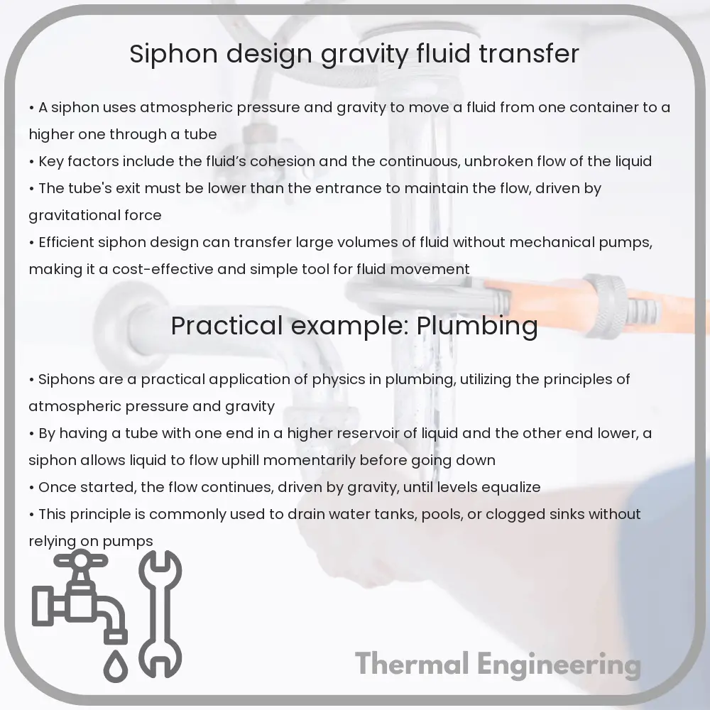
Siphon | Design & Gravity Fluid Transfer

Learn how siphons utilize gravity and atmospheric pressure to transfer liquids efficiently between containers at different elevations.

Siphon | Design & Gravity Fluid Transfer

Understanding Siphons: Principles and Applications

A siphon is a simple yet fascinating device used to transfer liquid from one container to another, typically from a higher elevation to a lower one, without the need for a pump. The operation of a siphon relies principally on the principles of gravity and atmospheric pressure. In this article, we’ll explore how siphons work, factors that affect their design, and some practical applications.

How Does a Siphon Work?

Essentially, a siphon consists of a tube with both ends open. To start the flow, the tube is filled with the liquid, which is initially at a higher level. One end of the tube is placed in the source container, while the other end is positioned in the destination container, which should be at a lower elevation than the source. Once the setup is complete and the siphoning starts, gravity pulls the liquid down through the tube, and a continuous flow is established.

The science behind siphoning involves atmospheric pressure and gravity. At the higher water level, gravity forces the liquid into the tube, creating suction at the top. As the liquid exits at the lower end, atmospheric pressure pushes the liquid from the higher reservoir into the tube to replace the exiting fluid. The critical factor for continuous flow is maintaining the outlet end of the tube below the water level of the source container.

Design Considerations for Effective Siphoning

  • Tubing Length and Diameter: The length and diameter of the tubing can influence the flow rate. Shorter tubes minimize resistance and can support a quicker flow. Larger diameters reduce resistance and allow for a higher volume of liquid to pass through per unit of time.
  • Material: The material of the tube should be selected based on the type of liquid being transferred. It must be durable and resistant to the liquid to avoid contamination and degradation.
  • Elevation Difference: There must be sufficient difference in elevation between the source and the destination container. The greater this difference, the stronger the gravitational force acting on the liquid, thus potentially increasing the flow rate.
  • Seal and Placement: Ensuring a good seal at the connection points and correct placement of the tube ends prevents air leaks, which can interrupt the siphon effect.

Applications of Siphons

Siphons find utility in various everyday and industrial applications:

  1. Aquarium Maintenance: Siphons are often used to change water in aquariums without disturbing the aquatic environment.
  2. Fuel Transfer: They are handy in transferring fuel from one container to another, especially avoiding direct contact and minimizing risk.
  3. Agriculture: In agricultural settings, siphons are used for irrigation purposes, helping distribute water across fields from water sources situated at higher elevations.
  4. Chemical Processes: In chemical industries, siphons help in transferring corrosive or hazardous liquids from one process unit to another, enhancing safety by avoiding pumps that might cause sparks.

Understanding the basic principle and design considerations for siphons not only aids in their effective application but also sparks curiosity about fundamental physical sciences principles at play. Whether it’s in simple tasks like siphoning gas or complex industrial operations, siphons demonstrate how fundamental physics can be applied to solve practical problems.

Conclusion

Siphons are a perfect example of how a simple principle can have widespread applications across various fields. By taking advantage of basic physical laws such as gravity and atmospheric pressure, siphons perform an essential function without the need for sophisticated technology. Education on such tools can be essential for innovative solutions in engineering and everyday life.

Magnetic Drive Pump | Sealless, Corrosive Handling

Learn about magnetic drive pumps, sealless pumps that use magnetic coupling for leak-free handling of hazardous liquids.

Magnetic Drive Pump | Sealless, Corrosive Handling

Understanding Magnetic Drive Pumps

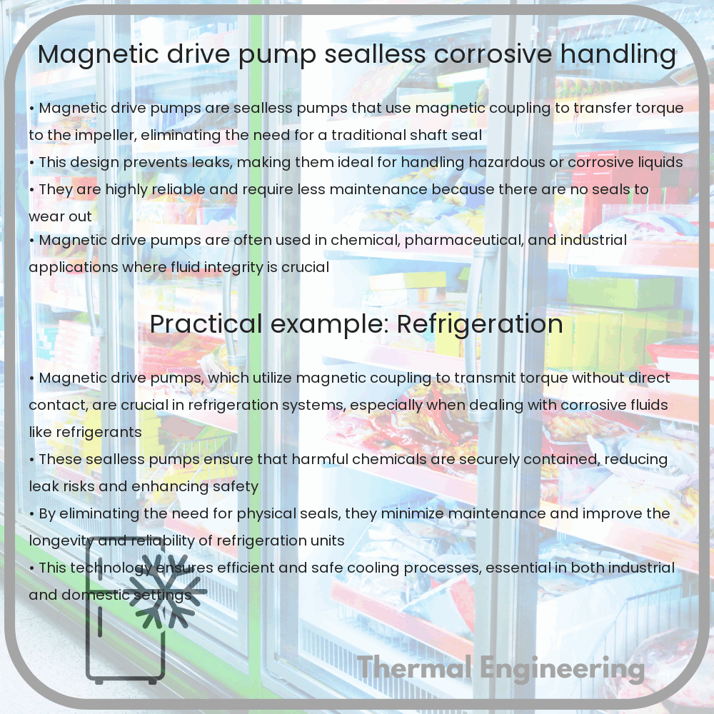
Magnetic drive pumps are a type of sealless pump used extensively in applications where leak prevention is critical. Unlike traditional pumps with dynamic seals, magnetic drive pumps utilize magnetic coupling to transmit torque to the impeller, thereby eliminating the need for shaft sealing mechanisms. This design makes them ideal for handling hazardous, corrosive, or otherwise dangerous liquids.

How Magnetic Drive Pumps Work

The key component that differentiates magnetic drive pumps from other pumps is their sealless design. The pump consists of two magnets: an outer magnet attached to the motor and an inner magnet connected to the pump impeller. The impeller, enclosed in a stationary containment shell, is driven magnetically through the shell by the outer magnet. Because the fluid being pumped does not come into contact with the mechanical parts of the motor or the exterior environment, the risk of leakage is significantly minimized.

Components of a Magnetic Drive Pump

  • Outer Magnet: Connected to the motor shaft, this drives the inner magnet via magnetic force through the containment shell.
  • Inner Magnet: Attached to the pump impeller, it transmits the driving force to the impeller, causing it to rotate and pump the fluid.
  • Containment Shell: A non-metallic, static barrier between the outer and inner magnet which segregates the fluid from the external environment and contains the pressure of the fluid.
  • Impeller: Rotates within the pump casing, moving the fluid through the pump and increasing the fluid’s pressure.

Advantages of Magnetic Drive Pumps

  • Leak-Free Operation: As there are no seals that can fail, the risk of leaks is significantly reduced, making these pumps ideal for hazardous or environmentally sensitive fluids.
  • Maintenance Cost: Lower maintenance costs due to the absence of seals or glands that require regular maintenance or replacement.
  • Corrosion Resistance: With the containment shell often made from corrosion-resistant materials like PTFE or ETFE, magnetic drive pumps can handle aggressive chemicals without degradation.
  • Energy Efficiency: Improved energy efficiency compared to conventional sealed pumps due to reduced friction losses from the absence of a shaft seal.

Applications of Magnetic Drive Pumps

Magnetic drive pumps are used in a wide range of industrial and commercial applications, including:

  1. Chemical processing industries, for transferring acid, solvents, and other hazardous chemicals safely.
  2. Pharmaceuticals production, where contamination-free processes are essential.
  3. Water treatment facilities, handling chlorinated water and other treatment chemicals.
  4. Photographic processing equipment, requiring precise and safe handling of chemicals.

Challenges and Limitations

Despite their numerous advantages, magnetic drive pumps do face certain limitations:

  • Heat Generation: The magnetic coupling can generate substantial heat, which if not properly managed, can affect pump performance and fluid integrity.
  • Magnetic Field Interference: Sensitive fluids or processes may be affected by the magnetic fields generated by the pump.
  • Initial Cost: Typically higher initial investment than conventional pumps, though this can be offset by lower maintenance and operating costs over time.

Conclusion

Magnetic drive pumps offer a reliable and efficient solution for pumping applications where leakage could pose significant risks to safety, the environment, or operational integrity. While they come with certain challenges, their benefits in terms of maintenance and operational safety are substantial, making them a favored choice in many industries where handling hazardous or corrosive liquids is a regular task.

Thermal Fluid Heater | High Temp Efficiency

Learn about thermal fluid heaters, their design, operation, efficiency, and applications in high-temperature industrial settings.

Thermal Fluid Heater | High Temp Efficiency

Understanding Thermal Fluid Heaters: High Temperature Efficiency

Thermal fluid heaters, also known as hot oil heaters, are a crucial component in industries where high-temperature process heating is required. These devices offer a highly efficient way to transfer heat by pumping thermal fluid through the heating system, without the need for additional pressure. In this article, we will explore the design, operation, and efficiency of thermal fluid heaters, particularly focusing on their high-temperature capabilities.

The Basics of Thermal Fluid Heater Operation

At its core, a thermal fluid heater involves a closed loop of thermal oil that is heated to a specified temperature and circulated to transfer heat to various consumer points. The system consists of a burner, a combustion chamber, a heat exchanger, and a pump to circulate the oil. Efficiency in these systems is driven by how well they can maintain a high temperature while minimizing energy loss.

Key Components and Design Features

The efficiency of thermal fluid heaters is significantly influenced by their design. Here are some of the critical components:

  • Burner: It controls the combustion of fuel, which is usually oil, gas, or coal. Modern burners are designed to maximize combustion efficiency and minimize emissions.
  • Combustion Chamber: It houses the burning fuel and must be well-insulated to contain heat effectively.
  • Heat Exchanger: This component transfers heat from the combustion gases to the thermal oil. Its design and material significantly affect efficiency.
  • Expansion Tank: As the thermal oil heats up, it expands. The expansion tank serves to accommodate this increase in volume without increasing pressure dangerously.

High Temperature Efficiency

Thermal fluid heaters are particularly valuable in high-temperature applications, typically operating up to 300°C, and in special cases, they can operate at higher temperatures, up to about 400°C. The efficiency of these heaters at high temperatures lies in their ability to retain heat and transfer it with minimal losses. Key factors contributing to high-temperature efficiency include:

  • Thermal Stability of Fluid: The type of oil used needs to maintain its properties at high temperatures without degrading.
  • Proper Insulation: Minimizing thermal losses through the insulation of pipes and the heater itself is critical.
  • Control Systems: Advanced digital controls allow precise temperature management and efficiency optimization.

Moreover, modern thermal fluid heaters incorporate features such as economizers and air pre-heaters, which recover heat from exhaust gases, thus improving overall system efficiency.

Applications of Thermal Fluid Heaters

Due to their high-temperature operation and efficiency, thermal fluid heaters find applications in various industries:

  • Chemical processing
  • Plastics manufacturing
  • Oil and gas processing
  • Food and beverage production
  • Textiles

Conclusion

Thermal fluid heaters are an essential system for industries requiring efficient high-temperature process heating. Their design ensures minimal heat loss while maintaining a high degree of thermal stability over prolonged operational periods. As technology advances, the efficiency of these systems continues to improve, leading to broader applications and enhanced energy management in industrial settings.

Understanding these systems in detail enables industries to choose, operate, and maintain them properly, leading to better energy utilization and sustainable production practices. Whether for heating large tanks, providing heat for reactors, or any high-heat activities, thermal fluid heaters are a robust solution, offering both performance and reliability.

Rotary Gear Flowmeter | Precision in Viscous Fluids

Explore how rotary gear flowmeters provide precise measurement of viscous fluids in various industrial applications.

Rotary Gear Flowmeter | Precision in Viscous Fluids

Understanding Rotary Gear Flowmeters: Precision Measurement in Viscous Fluids

Rotary gear flowmeters are indispensable tools in the precise measurement of fluid flow, especially in cases where the fluid has a high viscosity. Often found in a range of industries including chemical, food and beverage, and petroleum, these meters offer reliability and accuracy under conditions which challenge other types of flowmeters. This article delves into the principles of operation of rotary gear flowmeters, their design, and their applications.

Principle of Operation

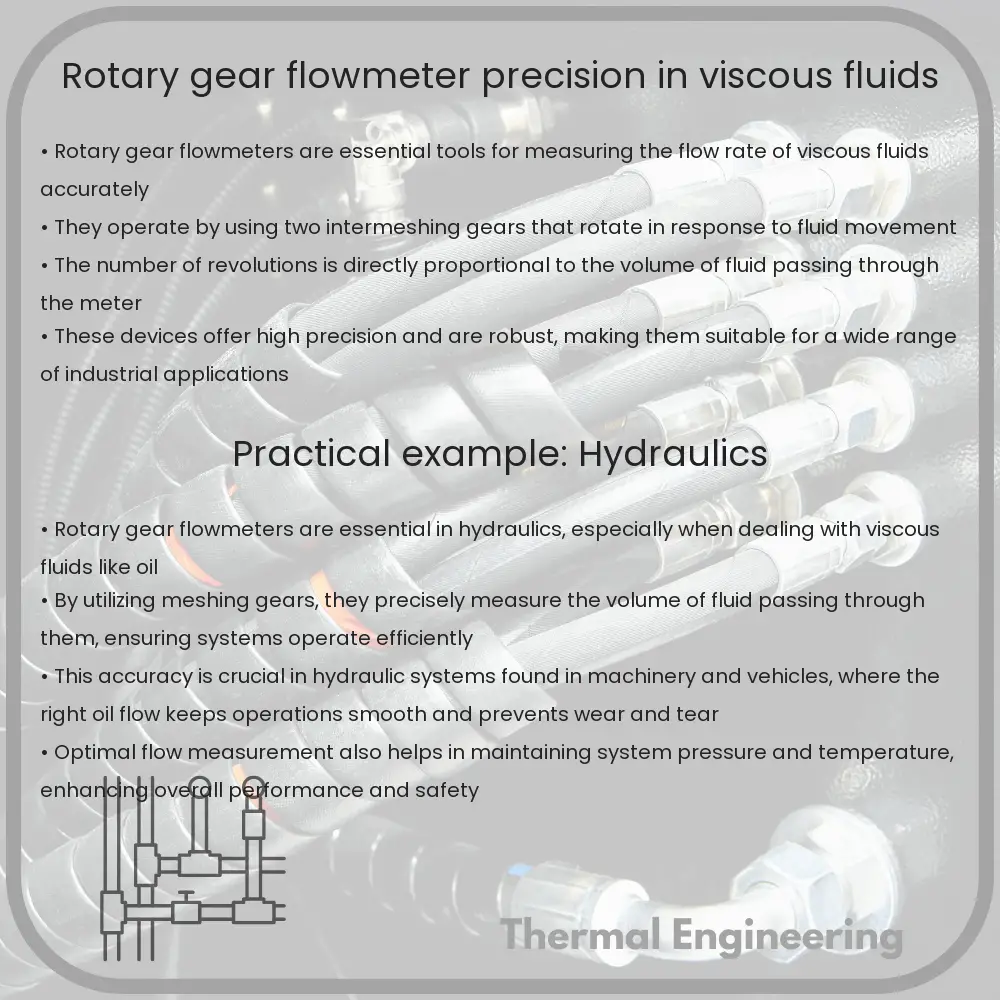
The basic operation of a rotary gear flowmeter revolves around the use of two intermeshing gears within a precision-machined chamber. As fluid enters the meter, it fills the spaces between the teeth of the gears, causing them to rotate. The movement of these gears is proportional to the volume of the fluid passing through the meter. A sensor detects the gear movements, converting them to a flow rate by counting the rotations.

Key Components and Design

  • Body: The body of the meter is typically made from metals such as stainless steel or aluminum, which provide durability and resistance to corrosion.
  • Gears: The gears are often crafted from stainless steel or an engineered plastic, depending on the nature of the fluid and the required durability.
  • Bearing and Seal: These components are crucial for smooth gear operation and to prevent fluid leakage. They must be selected based on the nature of the fluid and its operating temperature and pressure.
  • Sensor: The sensor plays a vital role in translating the physical rotation of the gears into electronic signals that can be quantified and analyzed.

Advantages of Rotary Gear Flowmeters

  • Accuracy: These flowmeters are known for their precision in measurement, particularly with viscous fluids, often within ±0.5% of the flow rate.
  • Viscosity Range: They perform well across a wide range of viscosities, from thin solvents to thick oils.
  • Low Maintenance: The design of rotary gear flowmeters minimizes the need for frequent maintenance.

Applications

Rotary gear flowmeters are versatile and can be used in several applications:

  1. Chemical Processing: Measurement of chemical dosing where precise quantities of viscous chemicals need to be added accurately.
  2. Food and Beverage: In the production of items like syrups, oils, and fats where volumetric measurements are crucial.
  3. Petroleum Industry: For the transfer and refining of crude oil and other viscous petroleum products.

Conclusion

Rotary gear flowmeters are crucial in providing accurate and reliable measurements of viscous fluids across various industrial applications. Their ability to handle a broad spectrum of viscosities and their robust design make them an ideal choice for industries requiring precise fluid handling and measurement. Understanding their operation and benefits helps in selecting the right flowmeter for any specific application, ensuring efficiency and effectiveness in industrial processes.