Facebook Instagram Youtube Twitter

High-speed airflow in tunnels

Learn about high-speed airflow in tunnels, its critical impact on engineering and how it influences safety and functionality in infrastructure like subways and rail systems.

High-speed airflow in tunnels

Understanding High-Speed Airflow in Tunnels

High-speed airflow in tunnels is a critical aspect of engineering that impacts the design, safety, and functionality of infrastructure such as subways, rail systems, and vehicle tunnels. This phenomenon involves complex fluid dynamics that can influence how tunnels are constructed and maintained. In this article, we explore the basics of high-speed airflow, its implications, and some of the engineering solutions used to manage it.

Why High-Speed Airflow Matters

The flow of air through a tunnel at high speeds can lead to several issues, including aerodynamic drag on vehicles, increased energy consumption, noise generation, and even structural vibrations. Moreover, for tunnels that support human travel, such as subways or train systems, ensuring air quality and adequate ventilation is crucial for safety and comfort.

Factors Affecting Airflow in Tunnels

The behavior of high-speed airflow in tunnels is influenced by several factors:

  • Tunnel Geometry: The shape and cross-sectional area of the tunnel impact how air moves through it. Tunnels with circular or oval cross-sections can facilitate smoother airflow compared to those with sharp corners or irregular shapes.
  • Ventilation Systems: These systems are designed to manage airflow and ensure adequate exchange of air inside the tunnel, helping to mitigate issues such as carbon dioxide buildup and other pollutants.
  • Traffic Volume: The amount and speed of vehicles or trains moving through the tunnel can push air in and out of the tunnel, significantly affecting the airflow patterns.
  • Environmental Conditions: External factors such as wind speed and atmospheric pressure can also influence the internal airflow characteristics of tunnels.

Engineer’s Nightmare: The Piston Effect

One notable phenomenon related to high-speed airflow in tunnels is the “Piston Effect”. This occurs when a train moves through a tunnel, acting like a piston that compresses air in front of it and creates a vacuum behind it. This effect can be described by the following basic equation:

\[ \Delta P = \frac{1}{2} \times \rho \times v^2 \]

Where:

  • \(\Delta P\) is the change in air pressure,
  • \(\rho\) (rho) is the air density,
  • \(v\) is the velocity of the train.

This pressure difference drives airflow through tunnel ventilation shafts and can create significant air movement that needs to be controlled, especially in high-speed rail systems.

Engineering Solutions to Manage Airflow

Engineers employ various strategies to manage the challenges posed by high-speed airflow in tunnels:

  1. Optimized Tunnel Design: Designing tunnel cross-sections to minimize resistance and facilitate smoother airflow. Aerodynamically efficient tunnel shapes are used to reduce the effects of the piston effect.
  2. Advanced Ventilation Systems: Implementing sophisticated ventilation systems that can adjust dynamically to changes in air pressure and flow requirements generated by tunnel traffic.
  3. Aeroelastic Tailoring: Applying materials and structural designs that can withstand or dampen vibrations caused by high-speed airflow, thereby enhancing structural integrity and longevity.
  4. Computational Fluid Dynamics (CFD): Using CFD simulations to predict airflow patterns and identify potential problems in the tunnel design phase, allowing engineers to make informed decisions and adjustments before construction.

Decoding the complex behavior of high-speed airflow in tunnels is essential for creating safe, efficient, and economically viable tunnel systems. Through the careful application of engineering principles and technology, modern tunnel designs can effectively manage these air movements, ensuring both operational success and passenger comfort.

Future Directions

Advances in technology may help further refine our understanding of tunnel aerodynamics. Future research and development efforts will likely focus on improving simulation tools, exploring new materials for tunnel construction, and developing even more sophisticated ventilation systems to efficiently manage the dynamics of high-speed airflow in ever-longer and deeper tunnels.

Heat sink design for LED lighting

Learn about the key aspects of heat sink design for LED lighting, focusing on material conductivity, surface area, and convection to enhance performance.

Heat sink design for LED lighting

Understanding Heat Sink Design for LED Lighting

As LEDs (Light Emitting Diodes) continue to replace traditional lighting systems, managing heat effectively remains a critical aspect of LED luminaire design. Excessive heat can degrade LED performance and reduce its lifespan. A properly designed heat sink plays a fundamental role in dispersing heat away from the LED, thereby ensuring efficiency and longevity of the light source. This article explores the basics of heat sink design specifically for LED lighting applications.

Why Heat Management is Crucial in LEDs

Unlike incandescent bulbs, which emit a large portion of energy as infrared radiation (heat), LEDs convert most of the electricity directly into light. However, some energy is still lost as heat within the semiconductor material. If this heat is not managed properly, it can lead to:

  • Reduced light output (lumen degradation).
  • Shifts in color spectrum.
  • Shorter overall lifespan of the LED.

Effective heat management through a well-designed heat sink ensures that these effects are minimized.

Principles of Heat Sink Design

To design an efficient heat sink for LED lighting, several factors should be considered:

  • Material Conductivity: The thermal conductivity of the material used for the heat sink affects how efficiently heat is conducted away from the LED. Materials like aluminum and copper are commonly used due to their high thermal conductivity.
  • Surface Area: Increasing the surface area of the heat sink allows more heat to dissipate into the surrounding environment. This is often achieved through the use of fins or pins.
  • Convection: Ensuring good air flow around the heat sink is crucial as it enhances the removal of heat via convection. In some designs, fans are added to increase airflow.
  • Attachment: The interface between the LED and the heat sink should have minimal thermal resistance. Thermal interface materials (TIMs), such as thermal paste or pads, are used to improve heat transfer at this junction.

Calculating Heat Sink Requirements

To determine the appropriate size and type of heat sink, the total amount of heat to be dissipated must be calculated. This can be estimated using the following formula:

\[Q = P_{in} – (V_f * I_f)\]

Where:

  • \(Q\) is the total power to be dissipated in watts.
  • \(P_{in}\) represents the input power.
  • \(V_f\) is the forward voltage of the LED.
  • \(I_f\) signifies the forward current.

The resulting value, \(Q\), gives the amount of heat (in watts) that the heat sink needs to dissipate. Subsequent thermal resistance (\(R_{th}\)) calculations can determine if a particular heat sink can handle this amount of heat over the ambient temperature conditions.

Advanced Heat Sink Technologies

As LED technology and applications grow, heat sink design also evolves. Some of the advanced cooling technologies include:

  • Phase Change Materials (PCMs): These materials absorb heat as they melt, changing from solid to liquid, thereby regulating the temperature around the LED.
  • Heat Pipes: Used to transfer heat away from the LED to a larger heat sink at a faster rate than standard solid heat sinks.
  • Active Cooling Systems: Systems that use electronic methods such as fans or blowers to increase heat dissipation efficiency.

Conclusion

Effective heat sink design is essential for the reliability and efficacy of LED lighting systems. By understanding and implementing the principles and calculations discussed, designers can ensure that their LED products perform optimally under various operational conditions. The ongoing advancements in heat sink technologies also offer numerous possibilities for enhancing LED cooling solutions in increasingly compact and powerful systems.

Fluid damping in mechanical systems

Learn about fluid damping, a key engineering concept used to reduce vibrations and enhance system stability in various mechanical applications.

Fluid damping in mechanical systems

Understanding Fluid Damping in Mechanical Systems

Fluid damping is a critical aspect in engineering that helps manage the effects of vibration, noise, and system stability across various mechanical applications. This fundamental concept plays a versatile role from automotive suspension systems to the safety components in skyscrapers. In this article, we’ll explore the basics of fluid damping, how it is implemented in mechanical systems, and its impact on the performance and longevity of engineering structures.

What is Fluid Damping?

Fluid damping involves the use of fluids to absorb and dissipate the energy from mechanical vibrations and shocks. When a mechanical system vibrates, parts of the system move through a fluid, usually a liquid such as oil, which resists the motion through viscous forces. The resistance transforms kinetic energy of the vibrating parts into thermal energy, thereby damping the motion and reducing the amplitude of the vibrations.

Key Mechanisms of Fluid Damping

There are primarily two mechanisms through which fluid damping operates in mechanical systems:

  • Viscous Damping: This is the most common form of fluid damping where the fluid’s viscosity is responsible for the resistance offered to the moving parts. Higher viscosity fluids typically provide greater damping effects.
  • Squeeze Film Damping: This occurs when fluid is squeezed in and out of a thin film between moving parts, such as in journal bearings or between the seismic mass and housing in accelerometers.

Mathematical Representation of Fluid Damping

The effect of fluid damping can be quantitatively described by the damping coefficient (c), which is a parameter in the damping force equation:

Fd = -c * v

Here, Fd is the damping force, c is the damping coefficient, and v represents the velocity of the moving component. The negative sign indicates that the damping force is always in opposition to the direction of motion, effectively reducing the movement.

Applications of Fluid Damping

Fluid damping finds its application in several critical engineering systems:

  • Automotive Industry: In shock absorbers and suspension systems, fluid damping is essential for improving ride quality and vehicle stability by mitigating the impact of uneven road surfaces.
  • Building Construction: Tall buildings and structures use damping systems filled with fluids to absorb energy from wind or seismic activity, enhancing structural integrity and lifespan.
  • Precision Instruments: Devices like accelerometers and gyroscopes utilize fluid damping to reduce noise and improve the accuracy of measurements.
  • Industrial Machinery: Fluid damping is used to reduce vibrations in rotors, gears, and other mechanical parts, protecting machinery from wear and extending its operational life.

Benefits of Fluid Damping

Implementing fluid damping in mechanical systems offers several advantages:

  • Enhanced Stability: By reducing vibrations, fluid damping enhances the stability and performance of machines and structures.
  • Increased Comfort: In vehicles, effective damping systems ensure a smoother ride for passengers by absorbing road shocks.
  • Extended Lifespan: Damping reduces the mechanical stress on components, decreasing wear and tear and extending the life of equipment.
  • Reduced Noise: Lowering vibration levels inherently reduces noise, contributing to a more quiet and comfortable environment.

In conclusion, fluid damping is a pivotal engineering practice that marries materials science with mechanical design to mitigate unwanted vibrations. Through its implementation, engineers can enhance the efficiency, safety, and comfort of various mechanical systems, thereby pushing the boundaries of modern engineering solutions.

Thermal hydraulics in nuclear reactors

Delve into the role of thermal hydraulics in ensuring the safety, efficiency, and stability of nuclear reactors through heat and fluid dynamics.

Thermal hydraulics in nuclear reactors

Understanding Thermal Hydraulics in Nuclear Reactors

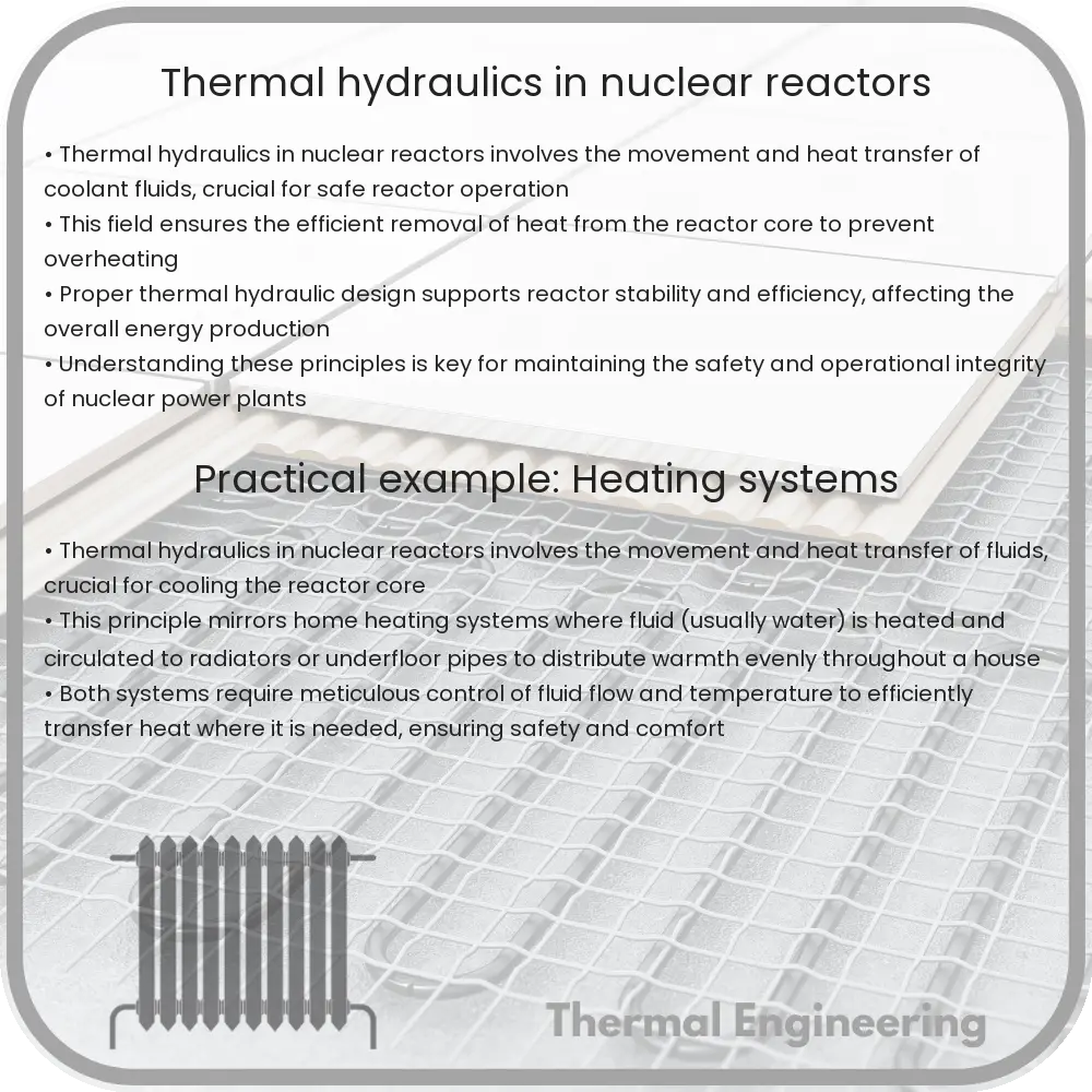
Thermal hydraulics plays a pivotal role in the safe and efficient operation of nuclear reactors. It is a specialized area of engineering that combines the principles of heat transfer and fluid mechanics to analyze and predict the behavior of fluids and heat in a nuclear reactor system. This article explores the key concepts of thermal hydraulics and its importance in nuclear power generation.

Core Concepts in Thermal Hydraulics

At the heart of thermal hydraulics are two principal concepts: heat transfer and fluid dynamics. Heat transfer in a nuclear reactor involves the movement of thermal energy from the reactor core, where heat is generated, to other parts of the system. Fluid dynamics refers to how liquids and gases behave within the reactor, especially the coolant which is essential in removing heat from the reactor core.

  • Heat Transfer: This includes mechanisms such as conduction, convection, and radiation. In nuclear reactors, heat is primarily transferred by convection where the coolant (usually water) absorbs heat from the reactor core and transports it away to be used in power generation or dissipated safely.
  • Fluid Dynamics: This involves the study of how the coolant flows through the reactor. It includes understanding how the fluid’s velocity, pressure, and temperature are influenced by interactions with reactor components and changes in heat transfer.

Importance of Thermal Hydraulics in Nuclear Reactors

Thermal hydraulics is critical for several reasons:

  1. Safety: Proper thermal hydraulic management ensures that the reactor operates within safe temperature limits, preventing overheating and potential meltdown.
  2. Efficiency: Optimizing heat transfer and fluid flow increases the efficiency of the heat to electricity conversion process, thereby improving the overall energy output of the reactor.
  3. Operational Stability: Stable thermal hydraulic conditions help maintain consistent reactor performance and avoid fluctuations that could lead to operational challenges or shutdowns.

Key Challenges in Thermal Hydraulics

While thermal hydraulics is a well-established field, it faces several challenges in practical applications:

  • Scaling: Experimental data obtained from scale models or separate effect test facilities need to be accurately scaled to real-world conditions. This requires complex mathematical models and simulations.
  • Complex Geometries: Nuclear reactors have intricate geometries that influence fluid flow and heat transfer patterns, making the prediction and analysis of these patterns quite challenging.
  • Material Interactions: Under high temperatures and radiation, materials used in the reactor may behave differently, impacting the thermal hydraulic performance.

Conclusion

Thermal hydraulics is a vital area of study in the field of nuclear engineering. It combines the disciplines of heat transfer and fluid mechanics to ensure the safe, efficient, and stable operation of nuclear reactors. Despite the challenges, advancements in computational fluid dynamics and improved experimental techniques continue to enhance our understanding and capability in this crucial area.

As nuclear power remains a significant part of the global energy mix, the role of thermal hydraulics in achieving safe and sustainable nuclear energy cannot be overstated. Professionals in this field continuously strive to refine their methods and technologies to meet the evolving demands of nuclear power production.

Airflow optimization in data centers

Learn how airflow optimization in data centers improves cooling efficiency, reduces energy costs, and extends equipment life.

Airflow optimization in data centers

Airflow Optimization in Data Centers

Airflow optimization in data centers is a critical aspect of engineering that ensures efficient cooling and minimizes energy consumption. Proper management of airflow can significantly reduce the risk of overheating, improve system reliability, and decrease operational costs. This article explores the basics of airflow management in data centers and discusses various strategies to optimize it.

Understanding Airflow in Data Centers

The primary goal of airflow optimization is to ensure that cool air reaches all the necessary equipment without being obstructed while simultaneously removing warm air. In data centers, servers and other electrical devices generate heat, which can lead to increased equipment failure rates and reduced efficiency if not properly dissipated.

Key Strategies for Airflow Optimization

  • Hot Aisle and Cold Aisle Layouts: This strategy involves organizing server racks in alternating rows with different temperature zones. The cold aisle faces the air conditioner output ducts, and the hot aisle collects the heated air and directs it towards the AC intake. This setup maximizes cooling efficiency and helps in maintaining optimal temperatures.
  • Raised Floor Systems: Using a raised floor can enhance airflow distribution. The space beneath the raised floor serves as a plenum for conditioned air, which can be efficiently delivered through perforated tiles directly in front of the racks.
  • Containment Systems: Containment systems like hot aisle or cold aisle containment can isolate the different temperature zones to prevent mixing of hot and cold air streams, enhancing the effectiveness of the cooling system.
  • Ventilation Optimization: Adjusting the position and size of vents can significantly impact air circulation effectiveness. Properly designed vents help avoid recirculation of hot air and ensure that cool air reaches all components evenly.
  • Regular Maintenance and Monitoring: Ensuring that the physical infrastructure is free from obstructions and regularly maintained is crucial. Monitoring tools and sensors can provide real-time data on temperature and airflow, facilitating timely adjustments.

Technological Innovations and Best Practices

Technological advancements have introduced sophisticated methods to improve airflow management, such as Computational Fluid Dynamics (CFD). CFD simulations can predict airflow patterns, temperature distribution, and potential hot spots, helping in designing more effective cooling strategies.

Benefits of Airflow Optimization

Optimizing airflow in data centers can lead to several benefits:

  • Energy Efficiency: Reducing the cooling load by effective airflow management leads to lower energy consumption and operational costs.
  • Extended Equipment Life: Maintaining optimal temperature ranges reduces wear and tear on hardware, leading to longer operational lifespans of equipment.
  • Improved System Performance: Efficient cooling can enhance performance and reduce the risk of downtime caused by overheating.

Airflow optimization is not just about enhancing cooling systems but about understanding and managing the entire ecosystem of a data center’s environment. By adopting the right strategies and technologies, businesses can ensure their data centers operate at peak efficiency, saving money and reducing their environmental impact.

Fluid flow in additive manufacturing

Delve into the critical role of fluid flow in optimizing additive manufacturing, a key factor in achieving precise and strong 3D printed products.

Fluid flow in additive manufacturing

Understanding Fluid Flow in Additive Manufacturing

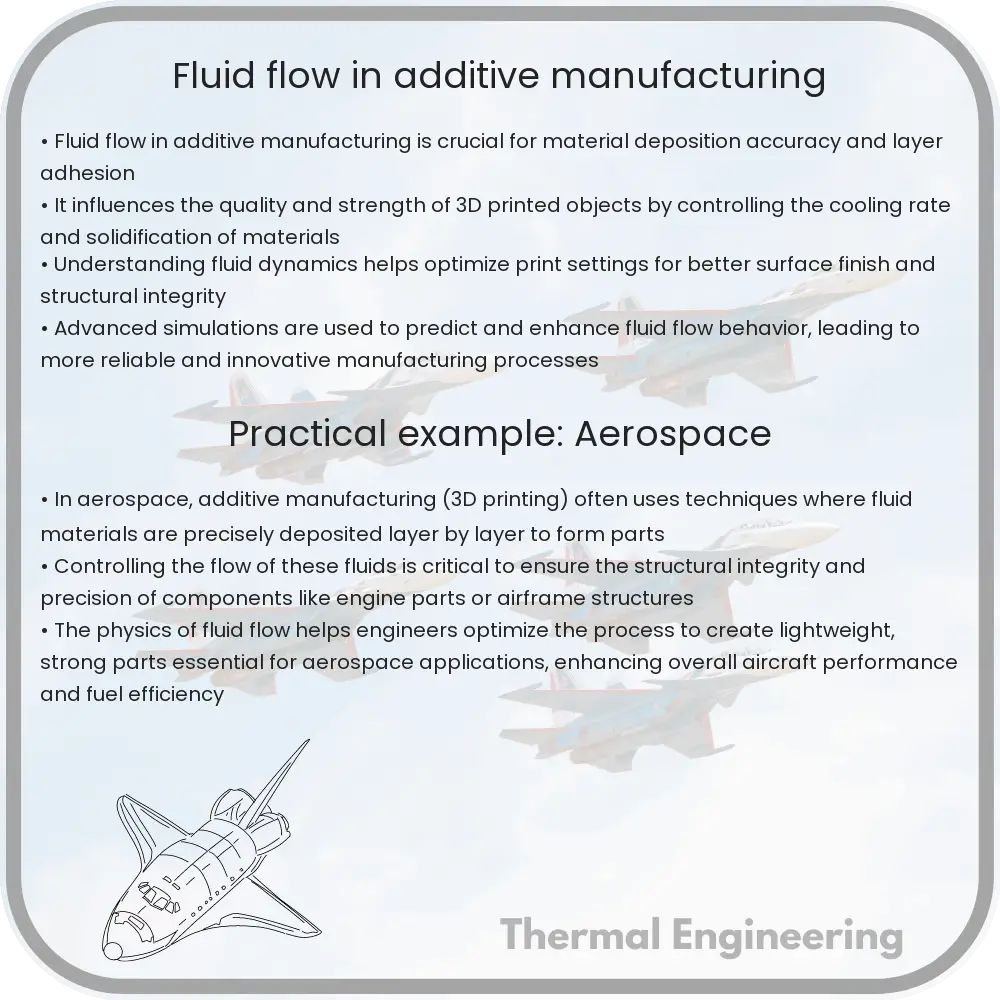
Additive manufacturing, also known as 3D printing, has revolutionized the way products are designed and manufactured in various industries, ranging from aerospace to biomedical engineering. One of the critical aspects of additive manufacturing that impacts the quality and characteristics of the final product is the fluid flow of the materials used during the printing process. This article explores the basics of fluid flow in additive manufacturing, highlighting its significance and the challenges involved.

Basics of Fluid Dynamics in Additive Manufacturing

In additive manufacturing, materials, typically polymers, metals, or ceramics, are deposited layer by layer to form a structure. The behavior of these materials as fluids, particularly their flow, viscosity, and solidification dynamics, plays a pivotal role in determining the integrity and resolution of the manufactured object. Fluid dynamics helps us understand how these materials can be manipulated to achieve desired properties in the final product.

Key Parameters Influencing Fluid Flow

  1. Viscosity: Viscosity is a measure of a fluid’s resistance to gradual deformation by shear or tensile stress. In additive manufacturing, the viscosity of the printing material affects its ability to flow smoothly through the printer’s nozzle and impacts the layering process.
  2. Temperature: Temperature control is crucial in additive manufacturing. For thermoplastic polymers, the temperature must be high enough to melt the material for extrusion but not so high as to cause decomposition. Metals require exact temperatures to ensure they melt and solidify at controlled rates to form strong bonds between layers.
  3. Print Speed and Pressure: The speed at which the material is extruded and the pressure applied during extrusion affect the material’s flow rate. Adjusting these parameters can help control the layer thickness and the formation of each layer, influencing the print’s resolution and strength.

Fluid Flow Equations in Additive Manufacturing

The behavior of fluids in additive manufacturing can often be described using basic fluid dynamics equations:

  • Continuity Equation: This equation, given by A1v1 = A2v2, where A is the cross-sectional area and v is the velocity of the fluid, ensures mass conservation of the fluid.
  • Navier-Stokes Equation: This set of equations governs the motion of viscous fluid substances. It is particularly useful in predicting the flow behavior of the material under different temperature and pressure conditions in the additive manufacturing process.

Challenges in Modelling Fluid Flow

Modelling fluid flow in additive manufacturing is complex due to the variability in material properties and the dynamic conditions under which printing occurs. Some of the challenges include:

  • Predicting the interactions between different materials, especially in multi-material printing.
  • Dealing with high nonlinearity due to temperature gradients and varying material properties through different stages of the printing process.
  • Overcoming the difficulty in accurately simulating the phase change (from solid to liquid and vice versa) that some materials undergo during printing.

Conclusion

The understanding and control of fluid flow in additive manufacturing are crucial for optimizing the print quality and mechanical properties of a product. Advanced simulations and real-time monitoring of fluid dynamics parameters enable manufacturers to fine-tune their processes for better results. Continuing advancements in this area are likely to improve the efficiency and capabilities of additive manufacturing technologies, making them more versatile and applicable in even more complex scenarios.

Improving our grasp of fluid dynamics within additive manufacturing settings continues to be a rich field for research and innovation, promising even more sophisticated manufacturing capabilities in the future.

Drag reduction in swimming

Learn about drag reduction techniques in swimming, including advancements in swimsuit design and swimming techniques to enhance performance.

Drag reduction in swimming

Understanding Drag Reduction in Swimming

Swimming is not just an art; it’s a science that involves understanding and manipulating physical properties like drag to enhance performance. Drag reduction is a crucial concept in competitive swimming, where minor enhancements can lead to significant performance improvements. In this article, we’ll delve into the basic principles of drag and explore some engineering strategies used to reduce drag in the sport of swimming.

What is Drag?

Drag, in fluid dynamics, is a force that opposes the motion of an object through a fluid. This fluid can be either a liquid, such as water, or a gas, such as air. In swimming, drag plays a critical role because swimmers need to overcome this resistive force to move efficiently through the water. Drag in swimming can be categorized into three main types:

  • Frictional drag: This arises from the friction between the swimmer’s body and the water and is influenced by the smoothness of the swimmer’s skin or suit.
  • Pressure drag: Also known as form drag, it occurs due to the shape of the swimmer moving against the water’s flow. The difference in pressure in front of and behind the swimmer contributes to this type of drag.
  • Wave drag: This type appears when the swimmer’s body moves near the surface, creating waves. Wave drag becomes significant especially at higher speeds and near the water’s surface.

Engineering Strategies for Drag Reduction

Several strategies can be employed to decrease drag, thereby enhancing a swimmer’s speed and efficiency in the water. These include both technique improvements and equipment enhancements:

  1. Swimming Techniques: Swimmers are trained to adopt specific body positions and movements to minimize drag. Streamlined body positions, where the body is aligned in a straight line, help in reducing the surface area exposed to the flow, thus reducing pressure and frictional drag.
  2. Swimsuit Design: Modern competitive swimwear is designed with fabrics that reduce frictional drag by being smoother and more compressive. These suits can also help in containing the body in a more hydrodynamic shape, thereby reducing form drag.
  3. Swim Cap and Goggles: Swimming caps made of latex or silicone can smooth out the hair and head shape, minimizing wave and frictional drag. Similarly, well-fitted goggles can reduce the frontal area exposed to the flow, helping to decrease both pressure and frictional drag.
  4. Improved Stroke Technique: Refining the stroke technique can significantly reduce drag. Techniques such as the ‘high elbow’ in freestyle minimize the arm’s frontal area exposed to water, reducing pressure drag.

Measuring and Analyzing Drag in Swimmers

To optimize performance, it’s crucial to measure and analyze drag for individual swimmers. This is typically done using computational fluid dynamics (CFD) models, tow-tank testing, or through the use of velocity meters during training. By understanding how different factors affect drag, coaches can tailor training and technique correction to maximize a swimmer’s efficiency and speed.

Conclusion

Drag reduction is a multifaceted area of study in swimming, intertwining elements of physics, engineering, and biomechanics. By employing various technological and technique-based strategies, swimmers can effectively reduce drag, leading to significant improvements in speed and performance. As research advances, ongoing innovations in swimwear design and swimming techniques continue to push the boundaries of what is possible in competitive swimming.

The pursuit of lower drag is not just about faster times; it’s about understanding and harnessing the principles of fluid dynamics to optimize human movement in water. This intersection of science and sport not only elevates athletic performance but also enhances our understanding of the physical world.

Fluid dynamics in agricultural irrigation

Explore how fluid dynamics optimizes agricultural irrigation systems for improved water management and crop yields.

Fluid dynamics in agricultural irrigation

Understanding Fluid Dynamics in Agricultural Irrigation

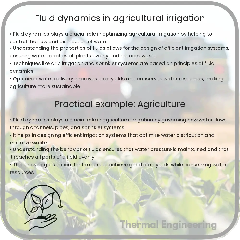
Fluid dynamics, a sub-discipline of fluid mechanics, plays a critical role in the design and efficiency of agricultural irrigation systems. This field of engineering focuses on the behavior of fluids in motion, providing essential insights into how water can be effectively and efficiently distributed in agricultural settings. By applying principles of fluid dynamics, farmers and engineers can optimize irrigation practices, enhance water conservation, and improve crop yields.

Basics of Fluid Dynamics

At its core, fluid dynamics involves the study of liquids and gases in motion. The fundamental equations governing fluid dynamics are the Navier-Stokes equations, which describe how the velocity field of a fluid evolves over time and space due to forces such as pressure gradients and external sources. Simplified models, such as the Bernoulli’s equation, are often used in irrigation to relate pressure, velocity, and height of fluid flow in pipelines and channels.

Application in Irrigation Systems

In agricultural irrigation, understanding and controlling the flow of water through pipes, channels, and sprinklers is essential. The following points highlight the key applications of fluid dynamics in agricultural irrigation:

  • Pipe Flow: The design of irrigation pipelines critically depends on principles such as laminar and turbulent flow. The Reynolds number, a dimensionless quantity, helps determine the flow regime in the pipe, influencing the efficiency of water transport and the energy costs of pumping.
  • Sprinkler Systems: The operation of sprinklers is influenced by the dynamics of droplets in the air, including their formation, size, and trajectory. Fluid dynamics models help optimize sprinkler design to maximize coverage and minimize water wastage due to wind drift and evaporation.
  • Drip Irrigation: Drip irrigation involves the slow release of water directly to the plant roots. Fluid dynamics plays a role in designing the emitters and ensuring a uniform flow rate, which is crucial for the effectiveness of the system.

Challenges and Innovations

Despite its advantages, implementing fluid dynamics in irrigation systems comes with challenges:

  • Variable Water Supply Conditions: Changes in water source levels and pressures can alter the flow characteristics, requiring adaptable system designs.
  • Clogging: Sediment in the water can clog irrigation systems, disrupting the flow patterns. Understanding the fluid dynamics helps in designing better filtration and maintenance routines.
  • Energy Efficiency: Pumping and maintaining pressure represents significant energy use in irrigation systems. Advanced fluid dynamics modeling helps optimize these processes to reduce energy consumption.

Innovations continue to emerge as engineers apply fluid dynamics to develop more efficient and sophisticated irrigation systems. For instance, computational fluid dynamics (CFD) tools allow for detailed simulations of fluid flow in irrigation equipment, leading to precision engineering solutions that can be tailored to specific environmental conditions and agricultural needs.

Conclusion

Fluid dynamics is integral to the design and optimization of agricultural irrigation systems. By understanding and applying the principles of this science, engineers can devise solutions that promote efficient water use, sustainability, and enhanced agricultural productivity. As technology advances, the integration of computational simulations will further refine and enhance the capabilities of irrigation systems, ensuring that water resources are used wisely to meet the growing global demand for food.

Overall, the application of fluid dynamics in agricultural irrigation not only supports better water management practices but also contributes to the broader goal of sustainable agricultural development.

Hemodynamics in artificial organs

Explore the critical role of hemodynamics in the design and function of artificial organs, focusing on blood flow dynamics and their engineering challenges.

Hemodynamics in artificial organs

Understanding Hemodynamics in Artificial Organs

Hemodynamics, the study of blood flow and its principles, plays a critical role in the design and functioning of artificial organs. As the development of artificial organs such as hearts, kidneys, and lungs advances, understanding the intricacies of hemodynamics within these devices is essential for their success and integration into human physiology.

Principles of Hemodynamics

The basic principles of hemodynamics involve the dynamics of blood flow, pressure, and resistance. These factors are crucial in maintaining adequate and stable functioning in artificial organs. The equations governing hemodynamic principles, such as the continuity equation and Bernoulli’s equation, help engineers understand and predict the behavior of blood flow through artificial systems.

  • Continuity Equation: A_{1} * v_{1} = A_{2} * v_{2}, where A is the cross-sectional area and v is the velocity of the blood flow. This equation asserts that blood flow (the product of area and velocity) is conserved along a streamline.
  • Bernoulli’s Principle: P + 1/2 * ρ * v^2 + ρgh = constant, where P is the fluid pressure, ρ is the fluid density, v is the velocity of the fluid, g is the acceleration due to gravity, and h is the height above a reference point. This principle helps in understanding the pressure changes in flowing blood.

Challenges in Designing Artificial Organs

One of the major challenges in designing artificial organs is mimicking the natural conditions as closely as possible. Artificial organs must handle the mechanical and biological responses of blood, such as viscosity and flow rates, without causing damage to blood cells or inducing clotting.

  • Material Compatibility: Materials used in artificial organs must be biocompatible and durable. They must not trigger immune reactions or cause thrombosis (clotting).
  • Shear Stress: Artificial organs must minimize shear stress, which can damage blood cells and activate clotting pathways. Engineers need to optimize the geometry and surface conditions of these devices to reduce turbulent flows.

Role of Hemodynamics in Artificial Heart Design

The design of artificial hearts is one of the most complex applications of hemodynamics. These devices need to replicate the pumping action of the natural heart. Key considerations include:

  1. Rate of blood flow: The artificial heart must be able to pump blood at a rate comparable to that of the natural heart, typically about 5 liters per minute for an adult under resting conditions.
  2. Pressure gradients: Proper pressure gradients must be maintained to ensure that blood can be delivered to all parts of the body effectively.
  3. Energy efficiency: The device should consume minimal power, thus reducing the burden on battery life and improving patient mobility.

Future of Hemodynamics in Artificial Organ Research

Advances in computational fluid dynamics (CFD) and materials science are pushing the boundaries of what is possible in the field of artificial organs. By simulating blood flow, pressure, and interaction with various materials, researchers can iterate designs rapidly and with high precision. Innovations such as 3D printing and nanotechnology are set to play significant roles in creating more efficient and patient-friendly artificial organs.

In summary, understanding and applying the principles of hemodynamics is crucial for the development of successful artificial organs. Through careful consideration of fluid dynamics, material science, and biological interactions, engineers and researchers are making significant strides in creating devices that can one day seamlessly replace their biological counterparts.

CFD simulation of combustion processes

Learn about CFD simulation, a key analytic tool in optimizing combustion processes, enhancing efficiency, and reducing emissions.

CFD simulation of combustion processes

Understanding CFD Simulation of Combustion Processes

Computational Fluid Dynamics (CFD) is a crucial tool in the engineering analysis of combustion processes. Combustion, the chemical process of releasing heat by burning fuels in the presence of oxygen, is fundamental in energy generation, propulsion systems, and various industrial processes. CFD simulations help engineers and scientists optimize combustion efficiency, reduce emissions, and enhance safety.

Basics of CFD in Combustion

CFD involves numerically solving the equations that govern fluid flows (Navier-Stokes equations) alongside chemical reactions to predict the behavior of gases and liquids in combustive environments. This approach combines fluid mechanics, heat transfer, and chemical kinetics, offering a detailed view of the combustion process without the need for extensive physical experiments.

Key Components in CFD Simulation of Combustion

  • Turbulence Modeling: Most combustion processes are turbulent. Accurately modeling turbulence is crucial for predicting how quickly and completely the fuel mixes with air, impacting combustion efficiency and emissions.
  • Reaction Mechanism: This includes all the chemical reactions that can occur during combustion. The complexity of the reaction mechanism can significantly affect the simulation’s accuracy and computational requirements.
  • Thermal Radiation: Significant in high-temperature environments, thermal radiation is the heat transfer via electromagnetic waves. Including its effects can be essential, especially in large-scale and high-temperature operations.

Mathematical Foundation of CFD for Combustion

The primary equations involved in CFD simulations of combustion are:

  1. Conservation of Mass: Also known as the Continuity Equation, represented by Δ*rho; + ∂(rho;*ui) / ∂xi = 0, where rho; is density and ui are the velocity components.
  2. Momentum Equation: Newton’s second law applied to fluid motion, often termed as Navier-Stokes equations.
  3. Energy Equation: Expresses the conservation of energy within the fluid system, crucial for tracking temperature distributions and identifying hot spots.
  4. Species Conservation: These equations ensure the conservation of each chemical species involved in the combustion process.

To solve these equations, CFD uses a variety of numerical methods, such as finite volume, finite element, and finite difference methods, to discretize them over a computational grid.

Applications of CFD in Combustion Engineering

The results of CFD simulations are essential in numerous fields:

  • Automotive Industry: Optimizing engines for better fuel efficiency and reduced emissions.
  • Power Generation: Designing more efficient combustion in furnaces and boilers.
  • Aerospace: Enhancing the performance of jet engines.
  • Environmental Engineering: Developing technologies for reducing pollutant emissions.

Challenges and Future Directions

While CFD has transformed combustion analysis, challenges remain. High-fidelity simulations require extensive computational resources and detailed chemical kinetics models, making some simulations very resource-intensive. With the advent of high-performance computing and more refined models, CFD is set to offer even more precise and useful insights into combustion processes.

As complexities in combustion applications grow, the role of advanced CFD techniques will become increasingly pivotal in addressing the pressing energy and environmental challenges of our time.