Facebook Instagram Youtube Twitter

Bubble dynamics in liquids

Understanding the behaviors and properties of bubbles in various liquids and their essential applications in multiple engineering fields.

Bubble dynamics in liquids

Bubble Dynamics in Liquids

Bubble dynamics is a fascinating area of engineering and physics, focusing on the behaviors and properties of bubbles in various liquids. This field is crucial for understanding phenomena in natural sciences, medical applications, and various engineering processes including chemical engineering and acoustic technologies.

Formation and Growth

Bubbles in liquids can form through several mechanisms such as boiling, cavitation, and aeration. Boiling occurs when a liquid reaches its boiling point and vapor bubbles form within the liquid itself. Cavitation, on the other hand, occurs when a liquid is subjected to rapid changes in pressure, leading to the formation of vapor cavities in regions where the pressure drops below the vapor pressure of the liquid.

The growth of a bubble can be described by the Rayleigh-Plesset equation, which is a differential equation that models the radius of a bubble as a function of time. This equation considers factors like surface tension, pressure difference, and viscosity. It is generally written as:

\[ R(t) \ddot{R} + \frac{3}{2} \dot{R}^2 = \frac{(p_∞(t) – p_v – P)}{\rho} – \frac{4 \mu \dot{R}}{R} – \frac{2 \sigma}{R \rho} \]

  • R(t) – Radius of the bubble at time t.
  • p∞(t) – Pressure in the liquid far from the bubble.
  • pv – Vapor pressure of the liquid.
  • P – Atmospheric pressure.
  • ρ – Density of the liquid.
  • μ – Viscosity of the liquid.
  • σ – Surface tension of the liquid.

Oscillations and Collapse

Once formed, bubbles might undergo oscillations. These oscillations are characterized by the expansion and contraction of the bubble radius over time. Several factors influence these oscillations including the properties of the liquid, the gases inside the bubble, and external forces like acoustic waves.

A dramatic aspect of bubble dynamics is the collapse phase, which can happen under the influence of surrounding liquid pressures that exceed the internal pressure of the bubble. This collapse can generate high temperatures and shock waves, a phenomenon that is critical in applications such as sonoluminescence and ultrasonic cleaning.

Applications in Engineering

The study of bubble dynamics has significant applications in several engineering fields:

  1. Chemical Engineering: Improving the efficiency of chemical reactors where gas-liquid reactions are crucial.
  2. Environmental Engineering: Applications in water treatment and aeration systems.
  3. Biomedical Engineering: In ultrasound technology for both diagnostics and treatment, such as in lithotripsy.
  4. Naval Engineering: Understanding cavitation can help in designing more efficient and less damaging propellers for vessels.

Bubble dynamics not only provides insights into a wide range of scientific and practical applications but also continues to be a rich field of research and development, highlighting the intricate behaviors and properties of bubbles in various liquid environments.

Challenges and Future Directions

Key challenges in the study of bubble dynamics include predicting bubble behavior under varying conditions and scaling laboratory observations to real-world applications. The future of bubble dynamics research lies in enhancing computational models, understanding multi-phase interactions, and exploring novel applications in environmental science and technology.

As we continue to expand our understanding of bubble dynamics, we pave the way for innovations across multiple disciplines, enhancing both technological capabilities and our fundamental scientific knowledge.
Hydrodynamic modeling of coastal engineering

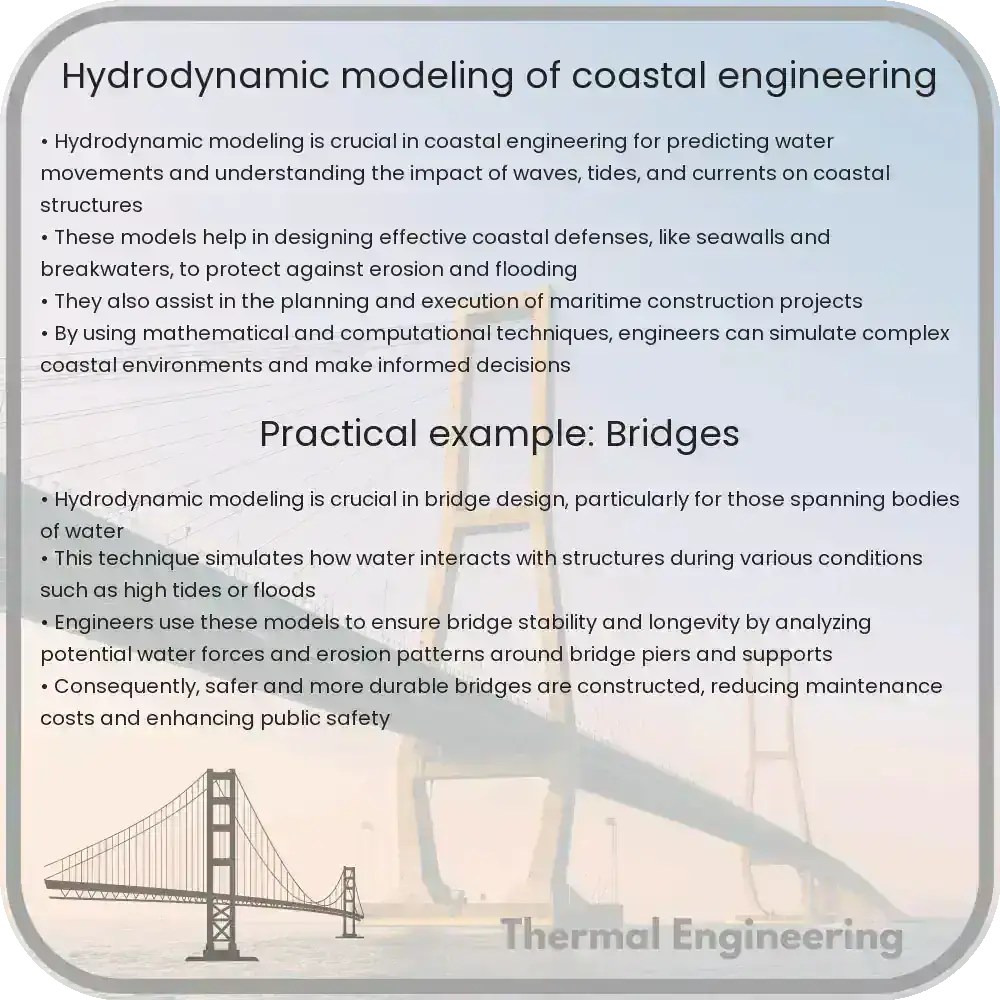
Hydrodynamic modeling in coastal engineering simulates water interactions with structures to manage erosion, floods, and infrastructure.

Hydrodynamic modeling of coastal engineering

Understanding Hydrodynamic Modeling in Coastal Engineering

Coastal engineering is a crucial field of engineering that deals with the management and construction within the coastal zone. The main objectives are the protection of coastlines from erosion, flooding, and sea-level rise, as well as the development of infrastructure capable of sustaining marine activities. An essential tool for achieving these goals is hydrodynamic modeling, which allows engineers to simulate and study the complex interactions between water and coastal structures.

What is Hydrodynamic Modeling?

Hydrodynamic modeling involves the use of mathematical formulas and algorithms to predict how water moves and behaves in different environments. In coastal engineering, this type of modeling is vital for predicting tide, wave, and storm surge scenarios, which can significantly impact coastal areas. The models help in understanding water behaviors such as currents, tides, and wave mechanics, which are critical for designing effective coastal protection and management strategies.

Key Components of Hydrodynamic Models

  • Bathymetry: The detailed measurement of the depth of water in oceans, seas, and lakes that influences how waves propagate and interact with land structures.
  • Topography: The arrangement of the natural and artificial physical features of an area. This includes beaches, dunes, and man-made structures like seawalls and jetties.
  • Wave characteristics: This includes data such as wave height, period, and direction, which are crucial for assessing the potential impact of waves on coastal structures and erosion patterns.

Mathematical Foundations of Hydrodynamic Modeling

At its core, hydrodynamic modeling in coastal engineering revolves around the fundamental equations of fluid dynamics, primarily the Navier-Stokes equations, which describe the movement of fluid substances. Simplified, these equations are:

  • Continuity Equation (to ensure mass conservation):
    $$\frac{\delta \rho}{\delta t} + \nabla \cdot (\rho \vec{v}) = 0$$
  • Momentum Equation (explaining the forces acting on the fluids):
    $$\rho (\frac{\delta \vec{v}}{\delta t} + \vec{v} \cdot \nabla \vec{v}) = -\nabla p + \rho \vec{g} + \mu \nabla^2 \vec{v}$$

Here \(\rho\) is the fluid density, \(\vec{v}\) is the velocity field, \(p\) is the pressure field, \(\vec{g}\) is the gravitational acceleration, and \(\mu\) is the dynamic viscosity.

Applications of Hydrodynamic Modeling in Coastal Engineering

Hydrodynamic models are implemented in various aspects of coastal engineering, including:

  1. Flood Risk Assessment: Estimating potential inundation areas and their corresponding water depths to enhance flood defenses.
  2. Marine Structure Design: Designing structures that can withstand the forces exerted by waves and tidal currents.
  3. Erosion Control: Predicting erosion patterns near coastlines and designing appropriate mitigation measures such as breakwaters or groynes.
  4. Environmental Management: Assessing the impact of human activities on coastal ecosystems and planning interventions to minimize environmental damage.

Hydrodynamic modeling is continually evolving with advances in computational resources and algorithms, enabling more precise and comprehensive predictions. Modern software packages and powerful computing architectures allow for real-time modeling and the visualization of complex scenarios, which are essential for effective decision-making in coastal management and engineering projects.

Conclusion

With the increasing threats posed by climate change, such as rising sea levels and more intense storm events, hydrodynamic modeling has become a cornerstone of coastal engineering. It offers a scientific basis for designing adaptive and resilient infrastructure, ensuring the safety and sustainability of coastal regions around the world.

Whether it’s used for designing coastal defenses, managing shoreline erosion, or planning marine habitats, effective use of hydrodynamic models is vital for informed decision-making and sustainable coastal management.

Fluid mechanics in microelectronics cooling

Exploring the role of fluid mechanics in optimizing microelectronics cooling methods to enhance device performance and efficiency.

Fluid mechanics in microelectronics cooling

Understanding Fluid Mechanics in Microelectronics Cooling

In the rapidly advancing world of technology, effective cooling systems are crucial for maintaining the reliability and efficiency of microelectronic devices. These devices, found in everything from smartphones to large data centers, generate significant amounts of heat that must be dissipated to prevent overheating and ensure optimal performance. Fluid mechanics plays a key role in the development and optimization of cooling techniques in microelectronics. This article explores the basic principles of fluid dynamics involved in microelectronics cooling and discusses common methods and innovations in this field.

Basics of Fluid Dynamics in Cooling

At its core, fluid mechanics in the context of microelectronics cooling involves the study of how liquids and gases behave when they are used to transfer heat away from electronic components. The effectiveness of a cooling medium is determined by properties such as thermal conductivity, specific heat capacity, and viscosity. These properties affect how efficiently heat can be transferred from the device to the cooling fluid.

Two primary methods of using fluid mechanics for cooling microelectronics are:

  • Active Liquid Cooling: Involves the circulation of a coolant liquid, like water or a glycol solution, through microchannels that are often fabricated directly into the chips. As the liquid passes through these channels, it absorbs heat from the electronics and carries it away.
  • Air Cooling: Utilizes fans or blowers to move air over surfaces of the components to dissipate heat. This method is generally less efficient than liquid cooling but is simpler and less costly to implement.

Heat Transfer Mechanisms Involved

Understanding the modes of heat transfer is fundamental in applying fluid mechanics to cool electronics. There are three primary modes of heat transfer:

  1. Conduction: Heat is transferred through materials by direct molecular contact. In microelectronics, heat conduction occurs from the silicon chip to the fluid in the cooling system.
  2. Convection: This process involves the transfer of heat by the physical movement of fluid over the heated surface. In cooling systems, this is achieved either naturally by the tendency of hot fluids to rise and cold ones to descend (natural convection) or by mechanically driven fluid motion (forced convection).
  3. Radiation: Heat is emitted in the form of electromagnetic waves and does not require any medium to propagate. Although significant in many engineering applications, radiation plays a smaller role in the cooling of microelectronics compared to conduction and convection.

Challenges and Innovations in Microelectronics Cooling

As devices become smaller and their power density increases, traditional air-cooling methods are often insufficient. This has led to innovative approaches to enhance heat transfer capabilities and efficiency. Some of these innovations include:

  • Microchannel Coolers: These involve very small channels, often micrometers in width, embedded within the chip to increase the surface area for heat exchange between the silicon and the coolant.
  • Phase Change Materials (PCMs): PCMs absorb heat by changing phase (from solid to liquid or vice versa) at a particular temperature. Integrating PCMs into microelectronics can help manage temperature spikes effectively.
  • Electrohydrodynamic (EHD) Cooling: Utilizes electric fields to enhance heat transfer by influencing the motion of conducting fluids near heat sources.
  • Jet Impingement Cooling: Involves directing a jet of coolant directly onto heated surfaces at high velocities for enhanced heat dissipation.

In conclusion, fluid mechanics significantly contributes to solving heat management challenges in microelectronics. By understanding the fundamentals of fluid behavior and heat transfer, engineers can design more effective cooling systems that keep pace with the increasing demands of modern microelectronics. Continued research and innovation are essential to develop even more efficient and compact cooling solutions in the future.

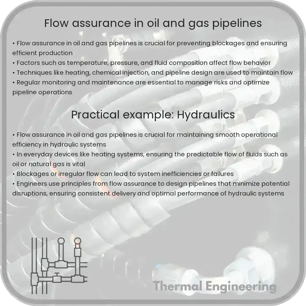
Flow assurance in oil and gas pipelines

Learn how flow assurance ensures efficient oil and gas pipeline operations by addressing challenges like hydrates, wax, and corrosion.

Flow assurance in oil and gas pipelines

Understanding Flow Assurance in Oil and Gas Pipelines

Flow assurance in the context of oil and gas industries refers to the successful transportation of hydrocarbon streams from the reservoir to the processing facilities while avoiding blockages, interruptions, or any other issues that can impede the flow. This discipline combines aspects of chemistry, thermodynamics, and fluid dynamics to ensure seamless, economically viable, and safe transport of oil and gas.

Key Challenges in Flow Assurance

The primary challenges in flow assurance include the formation of hydrates, wax, scale, asphaltenes, and corrosion. Each of these factors can lead to significant operational issues in pipelines and facilities. Here’s a brief overview:

  • Hydrate Formation: Natural gas hydrates are ice-like compounds where water molecules create a cage-like structure around a gas molecule. They can form under high pressure and low temperature conditions, potentially blocking pipelines.
  • Wax Deposition: Waxes are long-chain hydrocarbons that can precipitate and deposit on pipeline walls if the temperature of the pipeline falls below the wax appearance temperature (WAT).
  • Scale Formation: Scale, primarily consisting of carbonates and sulfates, can precipitate from produced water when conditions such as pressure, temperature, or composition change in the pipeline system.
  • Asphaltenes: Asphaltenes are complex high-molecular-weight hydrocarbons that can precipitate and cause blockages if the conditions of pressure and temperature lead to instability in the crude oil.
  • Corrosion: Driven by chemical reactions between the pipeline material and the fluids transported, or by microbial activity, corrosion can weaken pipelines and lead to leaks or bursts.

Techniques for Managing Flow Assurance

Addressing these challenges requires a combination of chemical treatments, mechanical solutions, monitoring, and thermal control methods:

  1. Thermal Insulation and Heating: Maintaining the temperature above certain thresholds can prevent the formation of hydrates and deposition of waxes. Techniques include direct electrical heating, pipeline insulation, and hot oil circulation.
  2. Chemical Injection: Various chemicals like hydrate inhibitors (e.g., methanol or glycol), wax inhibitors, scale inhibitors, and asphaltene dispersants are injected to prevent the respective issues. The choice and dosage of chemicals are crucial and must be optimized for effectiveness and economic efficiency.
  3. Pigging: Regularly running cleaning pigs (devices sent through the pipeline) helps in removing deposits and preventing accumulation.
  4. Pipeline Design: Optimized design and adequate pipe diameter can reduce problems. Additionally, proper layout planning considering topological features minimizes risks and operational difficulties.
  5. Real-time Monitoring and Control: Advanced sensor technologies and data analytics are employed for real-time monitoring of conditions inside the pipeline, allowing for timely interventions if flow-assurance issues are detected.

Flow assurance is critical for the economic and safe operation of hydrocarbon delivery systems. It requires an interdisciplinary approach and continuous innovation to address the evolving challenges in the industry. As the oil and gas sector continues to navigate complex extraction environments, flow assurance remains a pivotal area of focus.

Conclusion

Effective management of flow assurance issues not only ensures uninterrupted production but also helps in minimizing financial losses and environmental impacts associated with production delays and equipment failures. Through a combination of chemical, mechanical, and thermal strategies, along with ongoing research and technological advancements, the industry continues to address the challenges posed by the dynamic conditions of oil and gas extraction and transportation.

Gas-solid flows in industrial processes

Learn about gas-solid flows, their dynamics, and their critical role in enhancing efficiency and safety across multiple industrial processes.

Gas-solid flows in industrial processes

Understanding Gas-Solid Flows in Industrial Processes

Gas-solid flows are integral to many industrial processes, ranging from the pharmaceutical industry to the energy sector. These systems involve the motion of solid particles suspended in a gas stream, and their behavior impacts the efficiency, safety, and environmental compliance of many operational processes. Let’s explore the fundamental concepts and applications of gas-solid flows.

Basic Concepts of Gas-Solid Flows

In gas-solid flows, particles interact with a gas phase by exchanging momentum, heat, and mass. The fundamental challenge in understanding these flows lies in the complex dynamics governed by various forces acting on the particles, such as gravitational, drag, and inter-particle cohesion forces.

  • Drag Force: When a particle moves through a gas, it experiences a drag force opposite to the direction of motion. The magnitude of this force depends on the particle’s size, shape, and velocity relative to the gas, as well as the gas’s properties like viscosity and density.
  • Gravitational Force: The mass of a particle influences its tendency to settle under gravity, affecting how it moves through the gas.
  • Buoyant Force: Less dense particles might experience a buoyant force, which can counteract the effects of gravity.

The interplay of these forces determines the suspension and distribution of solid particles in the gas stream, influencing the flow patterns and behavior.

Equations Governing Gas-Solid Flows

Though the modeling of gas-solid flows can be complex, some key equations help in understanding these dynamics:

  • Conservation of Mass: Also known as the continuity equation, it is essential for determining changes in density of the flow as particles move and accumulate.
  • Conservation of Momentum: This equation helps predict the motion of particles and gas, considering the interaction forces:

For particles: Fdrag + Fgravity + Fbuoyancy = m * (dv/dt)

Where F represents forces, m the particle mass, and dv/dt the acceleration of the particle.

  • Granular Temperature: This concept, similar to temperature in thermodynamics, describes the kinetic energy distribution among particles, offering insights into the particle velocity fluctuations.

Applications in Industry

Gas-solid flows are used in numerous industrial applications:

  • Chemical Engineering: Processes like fluidized bed reactors rely on gas-solid flows for effective mixing and reaction rates.
  • Pharmaceuticals: In drug manufacturing, active pharmaceutical ingredients are often dried in spray dryers that use gas-solid flows to ensure uniform particle sizes and distributions.
  • Energy: Gasification processes convert solid fuels into combustible gases, requiring controlled gas-solid flows for efficiency.
  • Pollution Control: Electrostatic precipitators and cyclones separate particulates from exhaust gases using controlled gas-solid flows to reduce air pollution.

Conclusion

Gas-solid flows are complex but crucial to a wide variety of industrial operations. Understanding the fundamentals and behavior of such flows helps engineers to design more effective and efficient processing equipment. As computational power grows, predictive modeling will continue to enhance our ability to optimize these systems for better performance and sustainability.

By tackling the complexities of gas-solid interactions, industries can achieve improved yields, reduced costs, and meet stringent environmental standards, ultimately benefiting the global economy and ecological health.

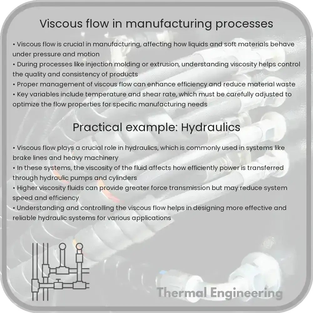
Viscous flow in manufacturing processes

Learn about viscous flow, a crucial fluid dynamics concept impacting various manufacturing processes from food to polymers.

Viscous flow in manufacturing processes

Understanding Viscous Flow in Manufacturing Processes

Viscous flow, a fundamental concept in fluid dynamics, plays a critical role in various manufacturing processes. From the food industry to polymer manufacturing, understanding how viscous fluids behave under different conditions is key to optimizing production techniques and enhancing product quality. In this article, we will explore what viscous flow is, its significance in manufacturing, and some common applications where viscous flow is a critical factor.

What is Viscous Flow?

Viscous flow refers to the motion of a fluid that is significantly affected by its viscosity. Viscosity itself is a measure of a fluid’s resistance to gradual deformation by shear or tensile stress. In simpler terms, it’s a measure of how “thick” or “sticky” a fluid is. Fluids with high viscosity (like honey) flow slower than those with low viscosity (like water).

Viscosity can be expressed mathematically by Newton’s law of viscosity:

\[ \tau = \mu \left(\frac{\partial u}{\partial y}\right) \]

where:

  • \(\tau\) is the shear stress
  • \(\mu\) is the dynamic viscosity of the fluid
  • \(\frac{\partial u}{\partial y}\) is the velocity gradient perpendicular to the direction of shear.

Role of Viscous Flow in Manufacturing

In manufacturing, controlling the flow characteristics of materials is crucial for achieving desired outcomes. Viscous flow impacts several aspects of manufacturing such as mixing, molding, coating, and extrusion. Here are some areas where viscous flow is particularly important:

  • Mixing: The viscosity of liquids determines how they can be mixed together. In industries like pharmaceuticals and foods, achieving a consistent mixture can affect the quality of the final product.
  • Molding: In the plastic and polymer industry, viscous flow behaviors of molten plastics are crucial in injection and blow molding processes to ensure that the materials fill the molds properly without creating defects.
  • Coating: The application of paints and coatings often requires careful consideration of viscosity to ensure a uniform layer is applied without dripping or uneven thickness.
  • Extrusion: The extrusion of plastics, ceramics, and food products relies on precise control of viscous flow to form products with desired shapes and finishes.

Applications of Viscous Flow

One of the most visible applications of viscous flow in manufacturing is in the food industry. For example, the extrusion process used in making pasta or cereals involves the viscous flow of dough through dies to shape the product. Similarly, in the pharmaceutical industry, the coating of tablets is an application where the viscosity of the coating solution must be tightly controlled to ensure each tablet is evenly coated.

Another significant application is in the production of synthetic fibers used in clothing. The viscosity of the polymer solution must be precisely controlled during the spinning process to produce fibers with uniform diameters.

Conclusion

Understanding and controlling viscous flow is essential across a range of manufacturing processes. By mastering the behavior of viscous fluids, manufacturers can improve product consistency, enhance production efficiency, and meet the demanding precision required in today’s marketplaces. As technology advances, the study of viscous flow will continue to play a pivotal role in the development of new and improved manufacturing techniques.

In summary, whether it comes to mixing pharmaceuticals, molding plastic toys, coating candies, or spinning synthetic fibers, viscous flow is a key engineering principle that helps make our everyday products better and processes more efficient.

Wind loading on structures

Learn about wind loading, a crucial factor in structural engineering that ensures buildings can withstand the forces exerted by wind.

Wind loading on structures

Understanding Wind Loading on Structures

Wind loading refers to the forces exerted by wind on a structure. These forces are critical considerations in the design and construction of buildings, bridges, and other structures to ensure safety and structural integrity. Below, we explore how wind loading affects structures, how engineers calculate these forces, and the standards and methods implemented to design structures that can withstand wind forces.

Basics of Wind Load

Wind load is the force exerted on a structure due to the wind blowing over its surfaces. It varies not only with the speed of the wind but also with the shape and orientation of the structure, surface roughness, and surrounding topography. Engineers categorize wind loads into three types:

  • Uplift Load – Wind pressure that could cause the roof or other components to lift off the structure.
  • Shear Load – Horizontal wind pressure that could tilt or shear the structure.
  • Lateral Load – Horizontal wind pressure exerted on the sides of the structure, potentially causing it to sway side to side.

Calculation of Wind Load

Engineers use various formulas to calculate wind loads. The basic equation used is derived from the Bernoulli’s equation for fluid dynamics and is given by:

\[ P = 0.5 * \rho * V^2 \]

Where:

  • P is the wind pressure,
  • ρ (rho) is the air density, and
  • V is the wind velocity.

However, calculating wind loads on a structure is more complex and involves considerations of various factors including gust factor, area of the structure exposed to the wind, the “drag coefficient” which depends on the shape of the structure, and “exposure category” which involves the roughness of surrounding terrain.

Building Codes and Standards

To ensure structural safety against wind loads, several international and local codes provide guidelines for design and construction. The American Society of Civil Engineers (ASCE) Standard ASCE 7 provides a detailed approach for calculating wind loads. This standard considers factors such as wind speed, topography, and type of terrain in different areas which classifies them into several exposure categories:

  • Exposure B – Urban and suburban areas, wooded areas or other terrain with numerous closely spaced obstructions having the size of single-family dwellings or larger.
  • Exposure C – Open terrain with scattered obstructions having heights generally less than 30 feet. This includes flat open country and grasslands.
  • Exposure D – Flat, unobstructed areas exposed to wind flowing over open water for a distance of at least one mile. This includes shorelines in hurricane-prone regions.

Design Strategies for Wind Loading

Engineers adopt various design strategies to manage wind loads on structures effectively. These include:

  • Aerodynamic shaping: Designing buildings in shapes that reduce wind forces, such as tapering or streamlining.
  • Structural damping: Including mechanisms that absorb some of the energy from the wind forces, thereby reducing the motion of the building.
  • Stiffening of structures: Increasing the stiffness of a building to handle greater wind load without excessive swaying or deformation.
  • Dynamic response analysis: Performing advanced calculations and simulations to predict how a structure will respond to dynamic wind loads.

Understanding and correctly applying the concept of wind loading is essential in the field of structural engineering to ensure that buildings and other structures can sustain the dynamic forces exerted by wind over time. This not only guarantees the longevity of the structure but also the safety and security of its occupants.

Aeroacoustic simulations

Learn how aeroacoustic simulations predict and analyze noise in fluid dynamics, crucial for aerospace and automotive design.

Aeroacoustic simulations

Understanding Aeroacoustic Simulations

Aeroacoustic simulations involve the study and prediction of noise generated by turbulent fluid flow, particularly in the context of air interacting with mechanical components such as aircraft wings, engines, and even vehicles. These simulations are crucial for designing quieter aerospace and automotive products, adhering to environmental regulations, and improving overall vehicle performance and passenger comfort.

The Basics of Aeroacoustics

Aeroacoustics is a branch of fluid dynamics that deals with sound generated by air movement, where the source of the noise is predominantly the result of turbulent fluid motion and pressure fields. The main challenge in aeroacoustic simulations lies in accurately predicting how fluctuating airflow will result in sound. This is crucial for designing quieter aircraft engines, improving the aerodynamic performance of car designs, and even optimizing the blades of wind turbines.

Key Principles and Algorithms in Aeroacoustic Simulations

To simulate aeroacoustic phenomena, engineers use various mathematical models and computational algorithms:

  • Direct Numerical Simulation (DNS): This technique fully resolves all scales of turbulent flow and acoustic waves. While highly accurate, DNS is also computationally expensive and typically only feasible for small-scale or academic studies.
  • Large Eddy Simulation (LES): LES resolves large-scale turbulence structures directly and models smaller scales. It strikes a balance between accuracy and computational feasibility, making it more suitable for industrial applications.
  • Reynolds-Averaged Navier-Stokes (RANS): RANS models average out fluctuations in turbulence, focusing on steady flow fields. It is less effective for detailed acoustic predictions but is useful for initial stage design and analysis.

Combining these fluid dynamics approaches with sound propagation models, engineers can estimate noise levels and identify major noise-producing mechanisms within a design.

Applications of Aeroacoustic Simulations

Aeroacoustic simulations are instrumental in several key industries:

  • Aerospace: Reducing the noise of jets, particularly during takeoff and landing, to meet regulatory standards and improve cabin comfort.
  • Automotive: Designing quieter vehicles by optimizing the shape and components to reduce aerodynamic drag and turbulence.
  • Renewable Energy: Enhancing the design of wind turbine blades to minimize noise without compromising on power efficiency.
  • Urban Planning: Assessing the impact of noise on environments near airports and highways.

Challenges in Aeroacoustic Simulations

Despite technological advances, several challenges remain in the field of aeroacoustic simulations:

  1. Scale: Simulating realistic engineering systems involves a wide range of scales both in space and time, requiring enormous computational resources.
  2. Model Accuracy: Bridging the gap between model simplifications and real-world complexities often leads to inaccuracies in predictions.
  3. Interdisciplinary Expertise: Effective aeroacoustic simulation requires in-depth knowledge of fluid dynamics, acoustics, computational mathematics, and engineering design.

As computational power continues to increase and algorithms become more sophisticated, the capabilities and accuracy of aeroacoustic simulations are expected to improve, playing a critical role in the future of design and engineering across multiple fields.

Fluid flow in art and architecture

Unveiling the role of fluid dynamics in shaping artistic and architectural designs by examining fluid behaviors in motion.

Fluid flow in art and architecture

Exploring Fluid Flow in Art and Architecture

Fluid flow, often studied under the discipline of fluid dynamics in engineering, plays a pivotal role in both art and architecture. This fascinating area explores how liquids and gases behave, which is crucial not just in engineering and physics, but also in the creation and conceptualization of artistic and architectural works. Here we’ll delve into how the principles of fluid flow influence and inspire designs in both fields.

Fluid Dynamics Basics

At its core, fluid dynamics is concerned with the behavior of fluids (liquids and gases) in motion. The basic equations governing fluid flow are the Navier-Stokes equations, which describe how the velocity field of fluids evolves. These equations take into consideration velocity, pressure, density, and viscosity of the flowing fluid. Although these can get mathematically complex, a simplified understanding can offer artists and architects a basis to incorporate fluid-like elements into their designs.

Fluid Flow in Art

In the realm of art, the visual representation of flowing water, swirling gases, and other fluid forms has always been a subject of fascination. Artists often utilize fluid dynamics concepts to create works that embody or represent the motion and chaos found in nature:

  • Painting: Techniques that involve pouring or dripping paint rely on gravity and the fluid properties of paint. Jackson Pollock famously used fluid dynamics knowingly or unknowingly in his drip paintings, where the viscosity of the paint along with the force of gravity and the angle of his canvas influenced how the paint flowed and spread.
  • Sculpture: Artists creating installations or sculptures sometimes need to understand fluid flow to create pieces that interact with water or air. The use of fluid dynamics can be seen in fountains or wind-driven sculptures, where the flow rate and pressure dictate the movement of water or air through the sculpture.

Fluid Flow in Architecture

Architecture often utilizes principles of fluid dynamics to design structures that can withstand the dynamic forces of wind and water, as well as to integrate water features aesthetically:

  • Building Aerodynamics: The study of how air moves around buildings is crucial in skyscraper design. For instance, the shape of the building can significantly affect the wind load. Architects often use wind tunnel testing to understand how their designs will perform in real-world conditions.
  • Water Features: Modern architecture includes dynamic water features that require an intricate understanding of fluid flow. Calculations related to pressure, flow rate, and turbulence are essential for designing fountains or waterfalls that are not only beautiful but also efficient.

Creative Integration of Fluid Dynamics

Both artists and architects have continually drawn inspiration from the natural flow of fluids. This integration often results in works that are not only visually striking but also reflect the complex behaviors of fluid movement. Understanding and exploring fluid dynamics allows creators to simulate natural processes, creating designs that resonate with the fluidity and rhythm seen in nature.

In conclusion, the blending of fluid dynamics in art and architecture showcases a beautiful intersection of science and creativity. As we advance technologically, the potential for new and innovative applications of fluid flow in these fields continues to grow, promising even more spectacular integrations of fluid dynamics in the designs of the future.

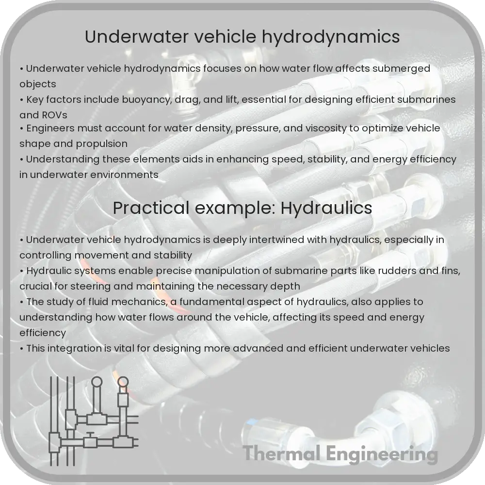
Underwater vehicle hydrodynamics

Explore the principles of underwater vehicle hydrodynamics, focusing on how vehicles like submarines and AUVs navigate water, and factors like buoyancy and drag affecting their movement.

Underwater vehicle hydrodynamics

Understanding Underwater Vehicle Hydrodynamics

Underwater vehicle hydrodynamics is a branch of fluid dynamics that deals specifically with how underwater vehicles move through water. This complex field of engineering combines principles from several areas, including marine engineering, mechanical engineering, and naval architecture, to optimize the design and operation of submersible and semi-submersible vehicles like submarines, Autonomous Underwater Vehicles (AUVs), and Remotely Operated Vehicles (ROVs).

Factors Influencing Underwater Hydrodynamics

The movement of underwater vehicles is influenced by various hydrodynamic factors, which include buoyancy, drag, lift, and thrust. To understand how these factors interact, it’s important to look at the equations and principles that govern them.

  • Buoyancy: Governed by Archimedes’ principle, buoyancy dictates that an underwater vehicle must displace a volume of water equivalent to its own weight to remain submerged at a neutral buoyancy.
  • Drag: This is the resistance an object encounters as it moves through the water. Drag force (FD) can be calculated using the equation: FD = (1/2) * ρ * v2 * CD * A, where ρ (rho) is the water density, v is the velocity of the vehicle relative to the water, CD is the drag coefficient, and A is the cross-sectional area.
  • Lift: Lift force is essential particularly in winged underwater vehicles, such as hydrofoils. It is generated by the motion of the vehicle through water and can be described by similar equations to those used in aerodynamics.
  • Thrust: Thrust must overcome drag for the vehicle to move forward, generated through propulsion systems such as propellers or jets.

Design Considerations and Challenges

Designing an efficient underwater vehicle involves balancing these forces while considering operational parameters and environmental conditions. The shape of the vehicle, type of materials used, and the configuration of its propulsion system are all critical decisions that impact hydrodynamic and operational efficiency.

  • Shape and Hull Design: The hydrodynamic efficiency of underwater vehicles is greatly influenced by their shape. Streamlined designs reduce drag, allowing for faster speeds and lower energy consumption.
  • Material Selection: Materials must withstand high pressures and corrosive saltwater environments while being lightweight to optimize performance.
  • Propulsion Systems: The design of the propulsion system must match the specific mission requirements of the vehicle, whether it’s high-speed maneuvering or stability for clear imaging and data collection.

Computational Tools in Hydrodynamic Analysis

Advancements in computational fluid dynamics (CFD) have significantly enhanced the capability to predict and analyze the hydrodynamic performance of underwater vehicles. CFD enables engineers to simulate fluid flow around the vehicle’s structure in a virtual environment, allowing for optimizations in design stages before physical models are tested in water tanks or real-world scenarios.

Applications of Underwater Vehicles

The optimized hydrodynamics of underwater vehicles are critical in a variety of applications:

  1. Military: Submarines and other underwater vehicles play key roles in defense, needing high speeds and maneuverability.
  2. Research and Exploration: AUVs are used in oceanography, environmental monitoring, and resource discovery, requiring vehicles to have a long operational range and stable movement capabilities.
  3. Industrial: In the offshore oil and gas industry, ROVs perform maintenance and installation tasks on underwater equipment.

The evolving field of underwater vehicle hydrodynamics continues to push the boundaries of what is possible in maritime engineering, improving the performance, efficiency, and capabilities of vehicles beneath the ocean’s surface.