Bernoulli’s Principle – Examples
Bernoulli’s Effect – Relation between Pressure and Velocity
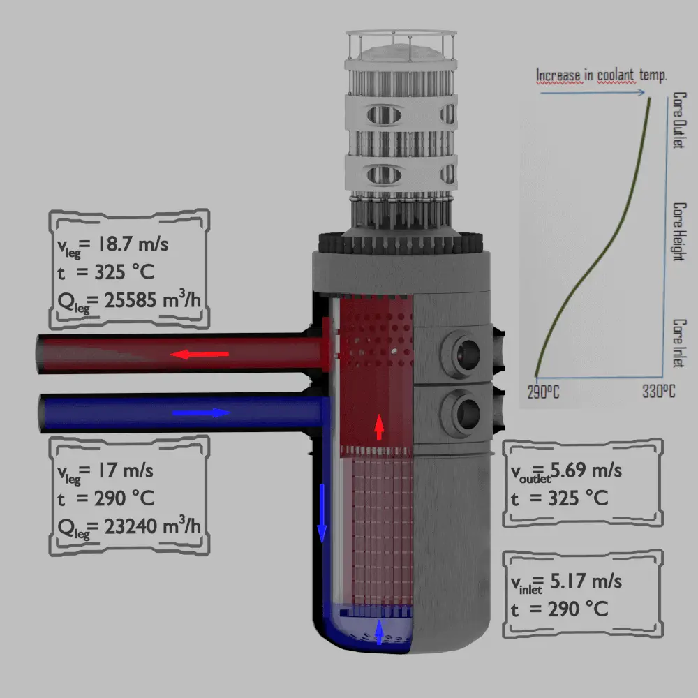
It is an illustrative example, following data do not correspond to any reactor design.
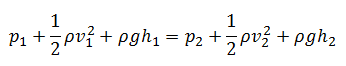
When the Bernoulli’s equation is combined with the continuity equation the two can be used to find velocities and pressures at points in the flow connected by a streamline.
The continuity equation is simply a mathematical expression of the principle of conservation of mass. For a control volume that has a single inlet and a single outlet, the principle of conservation of mass states that, for steady-state flow, the mass flow rate into the volume must equal the mass flow rate out.
Example:
Determine pressure and velocity within a cold leg of primary piping and determine pressure and velocity at a bottom of a reactor core, which is about 5 meters below the cold leg of primary piping.
Let assume:
- Fluid of constant density ⍴ ~ 720 kg/m3 (at 290°C) is flowing steadily through the cold leg and through the core bottom.
- Primary piping flow cross-section (single loop) is equal to 0.385 m2 (piping diameter ~ 700mm)
- Flow velocity in the cold leg is equal to 17 m/s.
- Reactor core flow cross-section is equal to 5m2.
- The gauge pressure inside the cold leg is equal to 16 MPa.
As a result of the Continuity principle the velocity at the bottom of the core is:
vinlet = vcold . Apiping / Acore = 17 x 1.52 / 5 = 5.17 m/s
As a result of the Bernoulli’s principle the pressure at the bottom of the core (core inlet) is:

Bernoulli’s Principle – Lift Force
In general, the lift is an upward-acting force on an aircraft wing or airfoil. There are several ways to explain how an airfoil generates lift. Some theories are more complicated or more mathematically rigorous than others. Some theories have been shown to be incorrect. There are theories based on the Bernoulli’s principle and there are theories based on directly on the Newton’s third law.
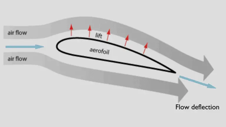
The explanation based on the Newton’s third law states that the lift is caused by a flow deflection of the airstream behind the airfoil. The airfoil generates lift by exerting a downward force on the air as it flows past. According to Newton’s third law, the air must exert an upward force on the airfoil. This is very simple explanation.
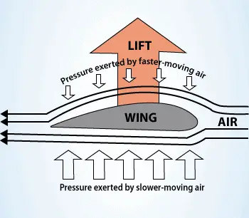
Bernoulli’s principle combined with the continuity equation can be also used to determine the lift force on an airfoil, if the behaviour of the fluid flow in the vicinity of the foil is known. In this explanation the shape of an airfoil is crucial. The shape of an airfoil causes air to flow faster on top than on bottom. According to Bernoulli’s principle, faster moving air exerts less pressure, and therefore the air must exert an upward force on the airfoil (as a result of a pressure difference).
The use of Bernoulli’s principle may not be correct. The Bernoulli’s principle assumes incompressibility of the air, but in reality the air is easily compressible. But there are more limitations of explanations based on Bernoulli’s principle. There are two main popular explanations of lift:
- Explanation based on downward deflection of the flow – Newton’s third law
- Explanation based on changes in flow speed and pressure – Continuity principle and Bernoulli’s principle
Both explanations correctly identifies some aspects of the lift forces but leaves other important aspects of the phenomenon unexplained. A more comprehensive explanation involves both changes in flow speed and downward deflection and requires looking at the flow in more detail.
See more: Doug McLean, Understanding Aerodynamics: Arguing from the Real Physics. John Wiley & Sons Ltd. 2013. ISBN: 978-1119967514
Bernoulli’s Effect – Spinning ball in an airflow
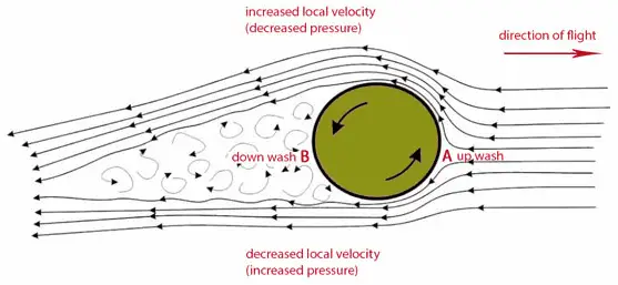
According to Bernoulli’s principle, faster moving air exerts less pressure, and therefore the air must exert an upward force on the ball. In fact, in this case the use of Bernoulli’s principle may not be correct. The Bernoulli’s principle assumes incompressibility of the air, but in reality the air is easily compressible. But there are more limitations of explanations based on Bernoulli’s principle.
The work of Robert G. Watts and Ricardo Ferrer (The lateral forces on a spinning sphere: Aerodynamics of a curveball) this effect can be explained by another model which gives important attention to the spinning boundary layer of air around the ball. On the side of the ball where the air stream and boundary layer are moving in the opposite direction (the bottom arrow), the boundary layer tends to separate prematurely. On the side of the ball where the air stream and boundary layer are moving in the same direction , the boundary layer carries further around the ball before it separates into turbulent flow. This gives a flow deflection of the airstream in one direction behind the ball. The rotating ball generates lift by exerting a downward force on the air as it flows past. According to Newton’s third law, the air must exert an upward force on the ball.
Torricelli’s law
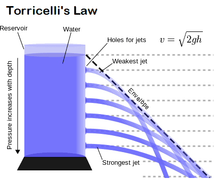
Torricelli’s law, also known as Torricelli’s principle, or Torricelli’s theorem, statement in fluid dynamics that the speed, v, of fluid flowing out of an orifice under the force of gravity in a tank is proportional to the square root of the vertical distance, h, between the liquid surface and the centre of the orifice and to the square root of twice the acceleration caused by gravity (g = 9.81 N/kg near the surface of the earth).
In other words, the efflux velocity of the fluid from the orifice is the same as that it would have acquired by falling a height h under gravity. The law was discovered by and named after the Italian scientist Evangelista Torricelli, in 1643. It was later shown to be a particular case of Bernoulli’s principle.
The Torricelli’s equation is derived for a specific condition. The orifice must be small and viscosity and other losses must be ignored. If a fluid is flowing through a very small orifice (for example at the bottom of a large tank) then the velocity of the fluid at the large end can be neglected in Bernoulli’s Equation. Moreover the speed of efflux is independent of the direction of flow. In that case the efflux speed of fluid flowing through the orifice given by following formula:
v = √2gh
We hope, this article, Bernoulli’s Principle – Examples, helps you. If so, give us a like in the sidebar. Main purpose of this website is to help the public to learn some interesting and important information about thermal engineering.