Extended Bernoulli’s Equation
There are two main assumptions, that were applied on the derivation of the simplified Bernoulli’s equation.
- The first restriction on Bernoulli’s equation is that no work is allowed to be done on or by the fluid. This is a significant limitation, because most hydraulic systems (especially in nuclear engineering) include pumps. This restriction prevents two points in a fluid stream from being analyzed if a pump exists between the two points.
- The second restriction on simplified Bernoulli’s equation is that no fluid friction is allowed in solving hydraulic problems. In reality, friction plays crucial role. The total head possessed by the fluid cannot be transferred completely and lossless from one point to another. In reality, one purpose of pumps incorporated in a hydraulic system is to overcome the losses in pressure due to friction.
Due to these restrictions most of practical applications of the simplified Bernoulli’s equation to real hydraulic systems are very limited. In order to deal with both head losses and pump work, the simplified Bernoulli’s equation must be modified.
The Bernoulli equation can be modified to take into account gains and losses of head. The resulting equation, referred to as the extended Bernoulli’s equation, is very useful in solving most fluid flow problems. The following equation is one form of the extended Bernoulli’s equation.
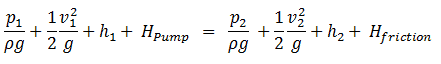
where:
h = height above reference level (m)
v = average velocity of fluid (m/s)
p = pressure of fluid (Pa)
Hpump = head added by pump (m)
Hfriction = head loss due to fluid friction (m)
g = acceleration due to gravity (m/s2)
The head loss (or the pressure loss) due to fluid friction (Hfriction) represents the energy used in overcoming friction caused by the walls of the pipe. The head loss that occurs in pipes is dependent on the flow velocity, pipe diameter and length, and a friction factor based on the roughness of the pipe and the Reynolds number of the flow. A piping system containing many pipe fittings and joints, tube convergence, divergence, turns, surface roughness and other physical properties will also increase the head loss of a hydraulic system.
Although the head loss represents a loss of energy, it does does not represent a loss of total energy of the fluid. The total energy of the fluid conserves as a consequence of the law of conservation of energy. In reality, the head loss due to friction results in an equivalent increase in the internal energy (increase in temperature) of the fluid.
Most methods for evaluating head loss due to friction are based almost exclusively on experimental evidence. This will be discussed in following sections.
The exit is at standard atmospheric pressure (101 kPa) and is 200 m higher.
Calculate the frictional head loss Hf, and compare it to the velocity head of the flow v2/(2g).
Solution:
Since the pipe diameter is constant, the average velocity and velocity head is the same everywhere:
vout = Q/A = 75 [m3/h] * 3600 [s/h] / 0.0113 [m2] = 1.84 m/s
Velocity head:
Velocity head = vout2/(2g) = 1.842 / 2*9.81 = 0.173 m
In order to find the frictional head loss, we have to use extended Bernoulli’s equation:
Head loss:
2 400 000 [Pa] / 1000 [kg/m3] * 9.81 [m/s2] + 0.173 [m] + 0 [m] = 101 000 [Pa] / 1000 [kg/m3] * 9.81 [m/s2] + 0.173 [m]+ 200 [m] + Hf
Hf = 244.6 – 10.3 – 200 = 34.3 m
We hope, this article, Extended Bernoulli’s Equation, helps you. If so, give us a like in the sidebar. Main purpose of this website is to help the public to learn some interesting and important information about thermal engineering.