Classification of Head Loss
The head loss of a pipe, tube or duct system, is the same as that produced in a straight pipe or duct whose length is equal to the pipes of the original systems plus the sum of the equivalent lengths of all the components in the system.
As can be seen, the head loss of piping system is divided into two main categories, “major losses” associated with energy loss per length of pipe, and “minor losses” associated with bends, fittings, valves, etc.
- Major Head Loss – due to friction in pipes and ducts.
- Minor Head Loss – due to components as valves, fittings, bends and tees.
The head loss can be then expressed as:
hloss = Σ hmajor_losses + Σ hminor_losses
Summary:
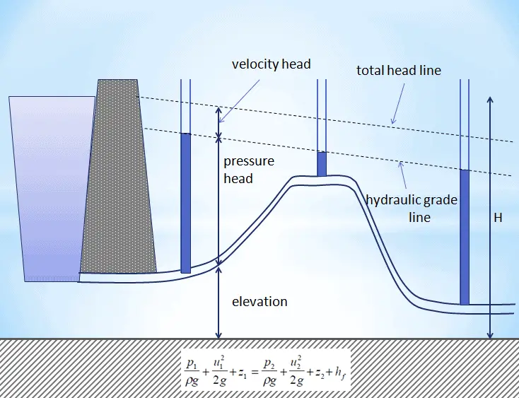
- Head loss or pressure loss are the reduction in the total head (sum of potential head, velocity head, and pressure head) of a fluid caused by the friction present in the fluid’s motion.
- Head loss and pressure loss represent the same phenomenon – frictional losses in pipe and losses in hydraulic components, but they are expressed in different units.
- Head loss of hydraulic system is divided into two main categories:
- Major Head Loss – due to friction in straight pipes
- Minor Head Loss – due to components as valves, bends…
- Darcy’s equation can be used to calculate major losses.
- A special form of Darcy’s equation can be used to calculate minor losses.
- The friction factor for fluid flow can be determined using a Moody chart.
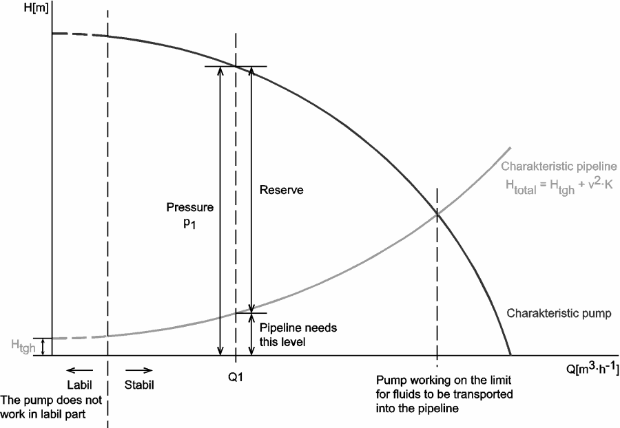
Why the head loss is very important?
As can be seen from the picture, the head loss is forms key characteristic of any hydraulic system. In systems, in which some certain flowrate must be maintained (e.g. to provide sufficient cooling or heat transfer from a reactor core), the equilibrium of the head loss and the head added by a pump determines the flowrate through the system.
We hope, this article, Classification of Head Loss, helps you. If so, give us a like in the sidebar. Main purpose of this website is to help the public to learn some interesting and important information about thermal engineering.