Head Loss – Pressure Loss
In the practical analysis of piping systems the quantity of most importance is the pressure loss due to viscous effects along the length of the system, as well as additional pressure losses arising from other technological equipments like, valves, elbows, piping entrances, fittings and tees.
At first, an extended Bernoulli’s equation must be introduced. This equation permits account of viscosity to be included in an empirical way and quantify this with a physical parameter known as the head loss.
- The first restriction on Bernoulli’s equation is that no work is allowed to be done on or by the fluid. This is a significant limitation, because most hydraulic systems (especially in nuclear engineering) include pumps. This restriction prevents two points in a fluid stream from being analyzed if a pump exists between the two points.
- The second restriction on simplified Bernoulli’s equation is that no fluid friction is allowed in solving hydraulic problems. In reality, friction plays crucial role. The total head possessed by the fluid cannot be transferred completely and lossless from one point to another. In reality, one purpose of pumps incorporated in a hydraulic system is to overcome the losses in pressure due to friction.
Due to these restrictions most of practical applications of the simplified Bernoulli’s equation to real hydraulic systems are very limited. In order to deal with both head losses and pump work, the simplified Bernoulli’s equation must be modified.
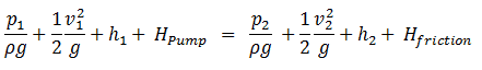
The Bernoulli equation can be modified to take into account gains and losses of head. The resulting equation, referred to as the extended Bernoulli’s equation, is very useful in solving most fluid flow problems. The following equation is one form of the extended Bernoulli’s equation.
where:
h = height above reference level (m)
v = average velocity of fluid (m/s)
p = pressure of fluid (Pa)
Hpump = head added by pump (m)
Hfriction = head loss due to fluid friction (m)
g = acceleration due to gravity (m/s2)
The head loss (or the pressure loss) due to fluid friction (Hfriction) represents the energy used in overcoming friction caused by the walls of the pipe. The head loss that occurs in pipes is dependent on the flow velocity, pipe diameter and length, and a friction factor based on the roughness of the pipe and the Reynolds number of the flow. A piping system containing many pipe fittings and joints, tube convergence, divergence, turns, surface roughness and other physical properties will also increase the head loss of a hydraulic system.
Although the head loss represents a loss of energy, it does does not represent a loss of total energy of the fluid. The total energy of the fluid conserves as a consequence of the law of conservation of energy. In reality, the head loss due to friction results in an equivalent increase in the internal energy (increase in temperature) of the fluid.
Most methods for evaluating head loss due to friction are based almost exclusively on experimental evidence. This will be discussed in following sections.
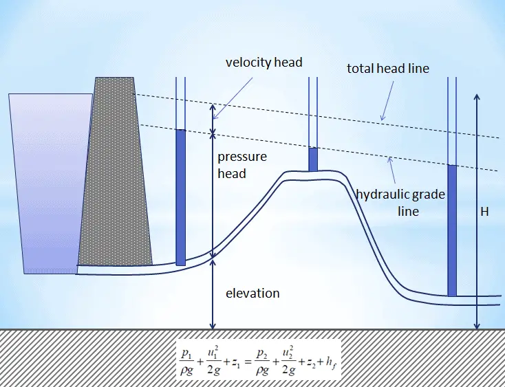
In fluid dynamics, head is a concept that relates the energy in an incompressible fluid to the height of an equivalent static column of that fluid. The units for all the different forms of energy in the Bernoulli’s equation can be measured also in units of distance, and therefore these terms are sometimes referred to as “heads” (pressure head, velocity head, and elevation head). Head is also defined for pumps. This head is usually referred to as the static head and represents the maximum height (pressure) it can deliver. Therefore the characteristics of all pumps can be usually read from its Q-H curve (flow rate – height).
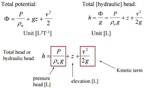
There are four types of potential (head):
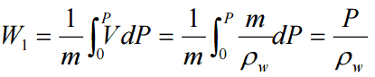
- Pressure potential – Pressure head: The pressure head represents the flow energy of a column of fluid whose weight is equivalent to the pressure of the fluid.
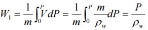 ρw: density of water assumed to be independent of pressure
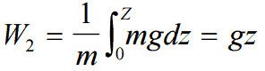
 - Elevation potential – Elevation head: The elevation head represents the potential energy of a fluid due to its elevation above a reference level.
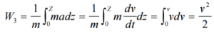
- Kinetic potential – Kinetic head: The kinetic head represents the kinetic energy of the fluid. It is the height in feet that a flowing fluid would rise in a column if all of its kinetic energy were converted to potential energy.
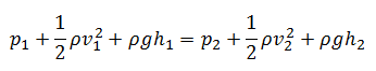
The sum of the elevation head, kinetic head, and pressure head of a fluid is called the total head. Thus, Bernoulli’s equation states that the total head of the fluid is constant.
Consider a pipe containing an ideal fluid. If this pipe undergoes a gradual expansion in diameter, the continuity equation tells us that as the pipe diameter increases, the flow velocity must decrease in order to maintain the same mass flow rate. Since the outlet velocity is less than the inlet velocity, the kinetic head of the flow must decrease from the inlet to the outlet. If there is no change in elevation head (the pipe lies horizontal), the decrease in kinetic head must be compensated for by an increase in pressure head.
The head loss (or the pressure loss) represents the reduction in the total head or pressure (sum of elevation head, velocity head and pressure head) of the fluid as it flows through a hydraulic system. The head loss also represents the energy used in overcoming friction caused by the walls of the pipe and other technological equipments. The head loss is unavoidable in real moving fluids. It is present because of the friction between adjacent fluid particles as they move relative to one another (especially in turbulent flow).
The head loss that occurs in pipes is dependent on the flow velocity, pipe diameter and length, and a friction factor based on the roughness of the pipe and the Reynolds number of the flow. Although the head loss represents a loss of energy, it does not represent a loss of total energy of the fluid. The total energy of the fluid conserves as a consequence of the law of conservation of energy. In reality, the head loss due to friction results in an equivalent increase in the internal energy (increase in temperature) of the fluid.
Most methods for evaluating head loss due to friction are based almost exclusively on experimental evidence. This will be discussed in following sections.
The exit is at standard atmospheric pressure (101 kPa) and is 200 m higher.
Calculate the frictional head loss Hf, and compare it to the velocity head of the flow v2/(2g).
Solution:
Since the pipe diameter is constant, the average velocity and velocity head is the same everywhere:
vout = Q/A = 75 [m3/h] * 3600 [s/h] / 0.0113 [m2] = 1.84 m/s
Velocity head:
Velocity head = vout2/(2g) = 1.842 / 2*9.81 = 0.173 m
In order to find the frictional head loss, we have to use extended Bernoulli’s equation:
Head loss:
2 400 000 [Pa] / 1000 [kg/m3] * 9.81 [m/s2] + 0.173 [m] + 0 [m] = 101 000 [Pa] / 1000 [kg/m3] * 9.81 [m/s2] + 0.173 [m]+ 200 [m] + Hf
Hf = 244.6 – 10.3 – 200 = 34.3 m
Classification of Head Loss
The head loss of a pipe, tube or duct system, is the same as that produced in a straight pipe or duct whose length is equal to the pipes of the original systems plus the sum of the equivalent lengths of all the components in the system.
As can be seen, the head loss of piping system is divided into two main categories, “major losses” associated with energy loss per length of pipe, and “minor losses” associated with bends, fittings, valves, etc.
- Major Head Loss – due to friction in pipes and ducts.
- Minor Head Loss – due to components as valves, fittings, bends and tees.
The head loss can be then expressed as:
hloss = Σ hmajor_losses + Σ hminor_losses
Summary:
- Head loss or pressure loss are the reduction in the total head (sum of potential head, velocity head, and pressure head) of a fluid caused by the friction present in the fluid’s motion.
- Head loss and pressure loss represent the same phenomenon – frictional losses in pipe and losses in hydraulic components, but they are expressed in different units.
- Head loss of hydraulic system is divided into two main categories:
- Major Head Loss – due to friction in straight pipes
- Minor Head Loss – due to components as valves, bends…
- Darcy’s equation can be used to calculate major losses.
- A special form of Darcy’s equation can be used to calculate minor losses.
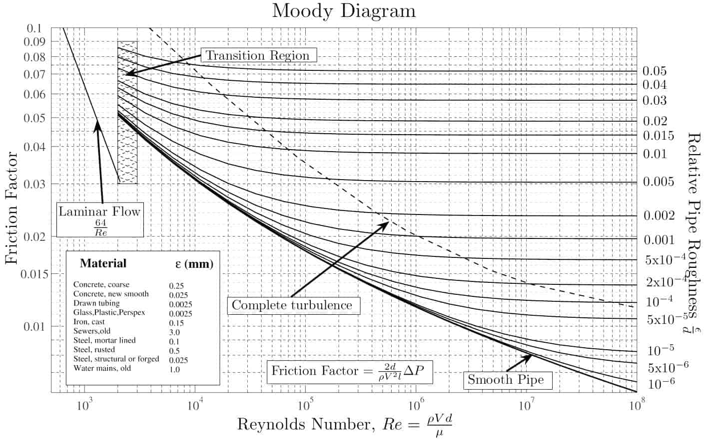
- The friction factor for fluid flow can be determined using a Moody chart.
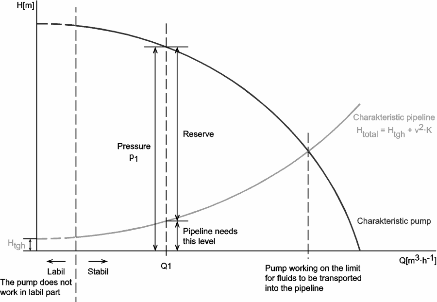
Why the head loss is very important?
As can be seen from the picture, the head loss is forms key characteristic of any hydraulic system. In systems, in which some certain flowrate must be maintained (e.g. to provide sufficient cooling or heat transfer from a reactor core), the equilibrium of the head loss and the head added by a pump determines the flowrate through the system.
Major Head Loss – Frictional Loss
See also: Major Head Loss – Frictional Losses
Major losses, which are associated with frictional energy loss per length of pipe depends on the flow velocity, pipe length, pipe diameter, and a friction factor based on the roughness of the pipe, and whether the flow is laminar or turbulent (i.e. the Reynolds number of the flow).
Although the head loss represents a loss of energy, it does not represent a loss of total energy of the fluid. The total energy of the fluid conserves as a consequence of the law of conservation of energy. In reality, the head loss due to friction results in an equivalent increase in the internal energy (increase in temperature) of the fluid.
By observation, the major head loss is roughly proportional to the square of the flow rate in most engineering flows (fully developed, turbulent pipe flow).
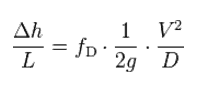
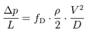
The most common equation used to calculate major head losses in a tube or duct is the Darcy–Weisbach equation (head loss form).
where:
- Δh = the head loss due to friction (m)
- fD = the Darcy friction factor (unitless)
- L = the pipe length (m)
- D = the hydraulic diameter of the pipe D (m)
- g = the gravitational constant (m/s2)
- V = the mean flow velocity V (m/s)
where:
- Δp = the pressure loss due to friction (Pa)
- fD = the Darcy friction factor (unitless)
- L = the pipe length (m)
- D = the hydraulic diameter of the pipe D (m)
- g = the gravitational constant (m/s2)
- V = the mean flow velocity V (m/s)
___________
- Consider that the length of the pipe or channel is doubled, the resulting frictional head loss will double.
- At constant flow rate and pipe length, the head loss is inversely proportional to the 4th power of diameter (for laminar flow), and thus reducing the pipe diameter by half increases the head loss by a factor of 16. This is a very significant increase in head loss, and shows why larger diameter pipes lead to much smaller pumping power requirements.
- Since the head loss is roughly proportional to the square of the flow rate, then if the flow rate is doubled, the head loss increases by a factor of four.
- The head loss is reduced by half (for laminar flow) when the viscosity of the fluid is reduced by half.
https://commons.wikimedia.org/w/index.php?curid=4681366
With the exception of the Darcy friction factor, each of these terms (the flow velocity, the hydraulic diameter, the length of a pipe) can be easily measured. The Darcy friction factor takes the fluid properties of density and viscosity into account, along with the pipe roughness. This factor may be evaluated by the use of various empirical relations, or it may be read from published charts (e.g. Moody chart).
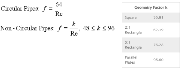
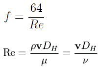
The Darcy friction factor for laminar (slow) flows is a consequence of Poiseuille’s law that and it is given by following equations:
The most common method to determine a friction factor for turbulent flow is to use the Moody chart. The Moody chart (also known as the Moody diagram) is a log-log plot of the Colebrook correlation that relates the Darcy friction factor, Reynolds number, and the relative roughness for fully developed flow in a circular pipe. The Colebrook–White equation:
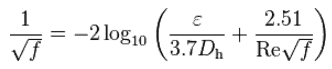
which is also known as the Colebrook equation, expresses the Darcy friction factor f as a function of pipe relative roughness ε / Dh and Reynolds number.
In 1939, Colebrook found an implicit correlation for the friction factor in round pipes by fitting the data of experimental studies of turbulent flow in smooth and rough pipes.
For hydraulically smooth pipe and the turbulent flow (Re < 105) the friction factor can be approximated by Blasius formula:
f = (100.Re)-¼
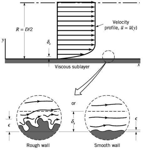 It must be noted, at very large Reynolds numbers, the friction factor is independent of the Reynolds number. This is because the thickness of laminar sublayer (viscous sublayer) decreases with increasing Reynolds number. For very large Reynolds numbers the thickness of laminar sublayer is comparable to the surface roughness and it directly influences the flow. The laminar sublayer becomes so thin that the surface roughness protrudes into the flow. The frictional losses in this case are produced in the main flow primarily by the protruding roughness elements, and the contribution of the laminar sublayer is negligible.
Minor Head Loss – Local Pressure Loss
See also: Minor Head Loss – Local Pressure Loss
In industry any pipe system contains different technological elements as bends, fittings, valves or heated channels. These additional components add to the overall head loss of the system. Such losses are generally termed minor losses, although they often account for a major portion of the head loss. For relatively short pipe systems, with a relatively large number of bends and fittings, minor losses can easily exceed major losses (especially with a partially closed valve that can cause a greater pressure loss than a long pipe, in fact when a valve is closed or nearly closed, the minor loss is infinite).
The minor losses are commonly measured experimentally. The data, especially for valves, are somewhat dependent upon the particular manufacturer’s design.
Generally, most of methods that are used in industry, define a coefficient K as a value for certain technological component.
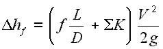
Like pipe friction, the minor losses are roughly proportional to the square of the flow rate and therefore they can be easy integrated into the Darcy-Weisbach equation. K is the sum of all of the loss coefficients in the length of pipe, each contributing to the overall head loss.
The following methods are of practical importance in local pressure loss calculations:
- Equivalent Length Method
- K-Method – Resistance Coefficient Method
- 2K-Method
- 3K-Method
See also: Minor Head Loss – Local Pressure Loss
Since the Reynolds number is inverse proportional to viscosity, then the resulting head loss becomes proportional to viscosity. Therefore, the head loss is reduced by half when the viscosity of the fluid is reduced by half, when the flow rate and thus the average velocity are held constant.
In general, it is not so simple to calculate pressure drops in fuel assemblies (especially the spacing grids) and it belongs to key know-how of certain fuel manufacturer. Mostly, pressure drops are measured in experimental hydraulic loops, rather than calculated.
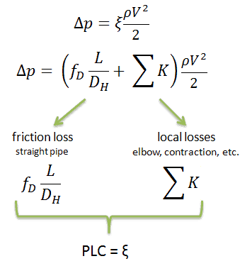
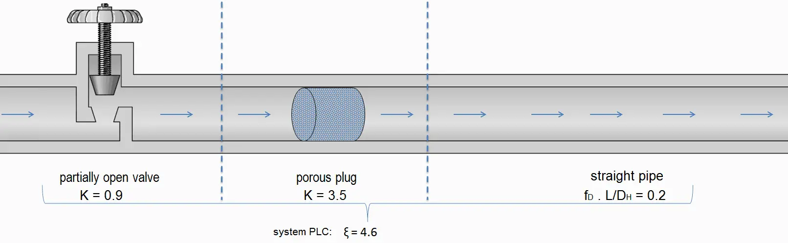
Engineers use the pressure loss coefficient, PLC. It is noted K or ξ (pronounced “xi”). This coefficient characterizes pressure loss of a certain hydraulic system or of a part of a hydraulic system. It can be easily measured in hydraulic loops. The pressure loss coefficient can be defined or measured for both straight pipes and especially for local (minor) losses.
Using data from below mentioned example, the pressure loss coefficient (only frictional from straight pipe) is equal to ξ = fDL/DH = 4.9. But the overall pressure loss coefficient (including spacing grids, top and bottom nozzles etc.) is usually about three times higher. This PLC (ξ = 4.9) causes that the pressure drop is of the order of (using the previous inputs) Δpfriction = 4.9 x 714 x 52/ 2 = 43.7 kPa (without spacing grids, top and bottom nozzles). About three times higher real PLC means about three times higher Δpfuel will be.
The overall reactor pressure loss, Δpreactor, must include:
- downcomer and reactor bottom
- lower support plate
- fuel assembly including spacing grids, top and bottom nozzles and other structural components – Δpfuel
- upper guide structure assembly
In result the overall reactor pressure loss – Δpreactor is usually of the order of hundreds kPa (let say 300 – 400 kPa) for design parameters.
Head Loss of Two-phase Fluid Flow
See also: Two-phase Pressure Drop
In contrast to single-phase pressure drops, calculation and prediction of two-phase pressure drops is much more sophisticated problem and leading methods differ significantly. Experimental data indicates that the frictional pressure drop in the two-phase flow (e.g. in a boiling channel) is substantially higher than that for a single-phase flow with the same length and mass flow rate. Explanations for this include an apparent increased surface roughness due to bubble formation on the heated surface and increased flow velocities.
We hope, this article, Head Loss – Pressure Loss, helps you. If so, give us a like in the sidebar. Main purpose of this website is to help the public to learn some interesting and important information about thermal engineering.