Fluid Acceleration
[/su_accordion]It is known that when the fluid is heated (e.g. in a fuel channel), the fluid expands (change in the fluid density) and increases its flow velocity as a result of the continuity equation (the channel cross-section remains the same). For a control volume that has a single inlet and a single outlet, this equation states that, for steady-state flow, the mass flow rate into the volume must equal the mass flow rate out.
Mass entering per unit time = Mass leaving per unit time
Another very important principle states (Bernoulli’s principle) that the increase in flow velocity in the heated channel causes the lowering of fluid pressure. This pressure loss can be also considered as a local pressure loss and can be calculated from the following equation:

Summary:
- Head loss of hydraulic system is divided into two main categories:
- Major Head Loss – due to friction in straight pipes
- Minor Head Loss – due to components as valves, bends…
- A special form of Darcy’s equation can be used to calculate minor losses.
- The minor losses are roughly proportional to the square of the flow rate and therefore they can be easy integrated into the Darcy-Weisbach equation through resistance coefficient K.
- As a local pressure loss fluid acceleration in a heated channel can be also considered.
There are following methods:
Flow rate through a reactor core – coolant acceleration
It is an illustrative example, following data do not correspond to any reactor design.

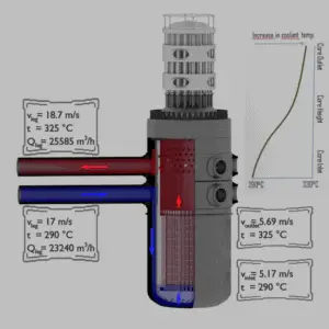
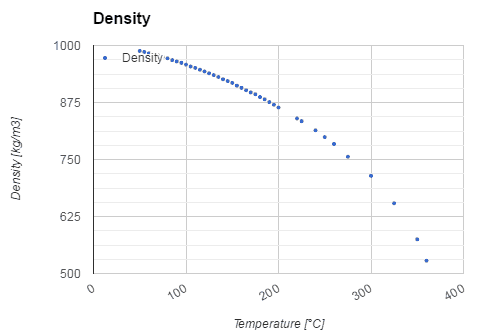
Pressurized water reactors are cooled and moderated by high-pressure liquid water (e.g. 16MPa). At this pressure water boils at approximately 350°C (662°F). Inlet temperature of the water is about 290°C (⍴ ~ 720 kg/m3). The water (coolant) is heated in the reactor core to approximately 325°C (⍴ ~ 654 kg/m3) as the water flows through the core.
The primary circuit of typical PWRs is divided into 4 independent loops (piping diameter ~ 700mm), each loop comprises a steam generator and one main coolant pump. Inside the reactor pressure vessel (RPV), the coolant first flows down outside the reactor core (through the downcomer). From the bottom of the pressure vessel, the flow is reversed up through the core, where the coolant temperature increases as it passes through the fuel rods and the assemblies formed by them.
Calculate:
- Pressure loss due to the coolant acceleration in an isolated fuel channel
when
- channel inlet flow velocity is equal to 5.17 m/s
- channel outlet flow velocity is equal to 5.69 m/s
Solution:
The pressure loss due to the coolant acceleration in an isolated fuel channel is then:
This fact has important consequences. Due to the different relative power of fuel assemblies in a core, these fuel assemblies have different hydraulic resistance and this may induce local lateral flow of primary coolant and it must be considered in thermal-hydraulic calculations.
We hope, this article, Fluid Acceleration – Pressure Loss, helps you. If so, give us a like in the sidebar. Main purpose of this website is to help the public to learn some interesting and important information about thermal engineering.

