Heat Generation in Nuclear Reactors
As was written, a nuclear power plant (nuclear power station) looks like a standard thermal power station with one exception. The heat source in the nuclear power plant is a nuclear reactor. As is typical in all conventional thermal power stations the heat is used to generate steam which drives a steam turbine connected to a generator which produces electricity. But in nuclear power plants reactors produce enormous amount of heat (energy) in a small volume. The density of the energy generation is very large and this puts demands on its heat transfer system (reactor coolant system).
For a reactor to operate in a steady state, all of the heat released in the system must be removed as fast as it is produced. This is accomplished by passing a liquid or gaseous coolant through the core and through other regions where heat is generated. The heat transfer must be equal to or greater than the heat generation rate or overheating and possible damage to the fuel may occur. The nature and operation of this coolant system is one of the most important considerations in the design of a nuclear reactor.
It should be noted that from a strictly nuclear standpoint, there is theoretically no upper limit to the reactor thermal power, which can be attained by any critical reactor having sufficient excess of reactivity to overcome its negative temperature feedbacks. In each nuclear reactor, there is a direct proportionality between the neutron flux and the reactor thermal power. The term thermal power is usually used, because it means the rate at which heat is produced in the reactor core as the result of fissions in the fuel. Moreover, for a short period, a critical reactor does not need to have high excess of reactivity as in case of rapid reactivity excursions.
In short, almost any reactor is able to exceed the ability of heat removal of its coolant system. Beyond this point, the fuel would heat up and can reach very high temperatures. This situation must be avoided by reactor operator and by reactor safety systems. It is essential, that the heat generation – heat removal rate balance must be maintained to prevent these temperatures that might result in the failure of fuel or other structural materials. In reactor engineering, the thermal-hydraulics of nuclear reactors describe the effort involving the coupling of heat transfer and fluid dynamics to accomplish the desired heat removal rate from the core under both normal operation and accident conditions.
Heat Production in Fuel Elements
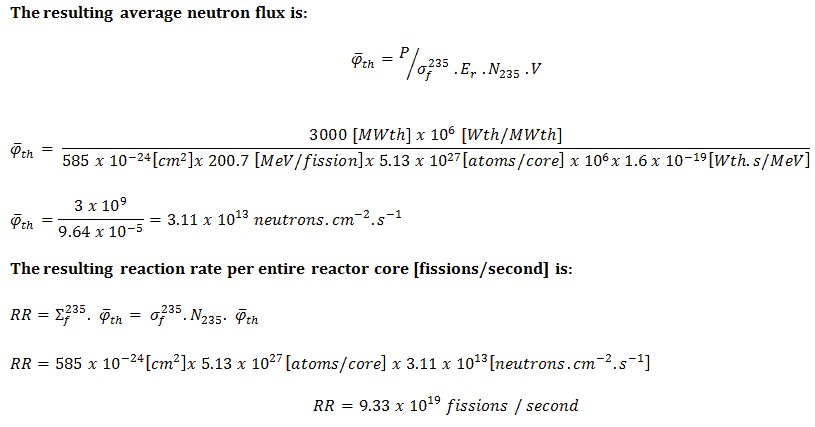
In nuclear reactors, there is a direct proportionality between the neutron flux and the reactor thermal power. This proporcionality is determined by the fission reaction rate per unit volume (RR = Ф . Σ). The fission reaction rate within a nuclear reactor is controlled by several factors. For simplicity let assume that the fissionable material is uniformly distributed in the reactor. In this case, the macroscopic cross-sections are independent of position. Multiplying the fission reaction rate per unit volume (RR = Ф . Σ) by the total volume of the core (V) gives us the total number of reactions occurring in the reactor core per unit time. But we also know the amount of energy released per one fission reaction to be about 200 MeV/fission. Now, it is possible to determine the rate of energy release (power) due to the fission reaction. It is given by following equation:
P = RR . Er . V = Ф . Σf . Er . V = Ф . NU235 . σf235 . Er . V
where:
P – reactor power (MeV.s-1)
Ф – neutron flux (neutrons.cm-2.s-1)
σ – microscopic cross section (cm2)
N – atomic number density (atoms.cm-3)
Er – the average recoverable energy per fission (MeV / fission)
V – total volume of the core (m3)
Solution:
The amount of fissile 235U per the volume of the reactor core.
m235 [g/core] = 100 [metric tons] x 0.02 [g of 235U / g of U] . 106 [g/metric ton] = 2 x 10⁶ grams of 235U per the volume of the reactor core
The atomic number density of 235U in the volume of the reactor core:
N235 . V = m235 . NA / M235
= 2 x 10⁶ [g 235 / core] x 6.022 x 10²³ [atoms/mol] / 235 [g/mol]
= 5.13 x 1027 atoms / core
The microscopic fission cross-section of 235U (for thermal neutrons):
σf235 = 585 barns
The average recoverable energy per 235U fission:
Er = 200.7 MeV/fission
In general, the nuclear fission results in the release of enormous quantities of energy. The amount of energy depends strongly on the nucleus to be fissioned and also depends strongly on the kinetic energy of an incident neutron. In order to calculate the power of a reactor, it is necessary to be able precisely identify the individual components of this energy. At first, it is important to distinguish between the total energy released and the energy that can be recovered in a reactor.
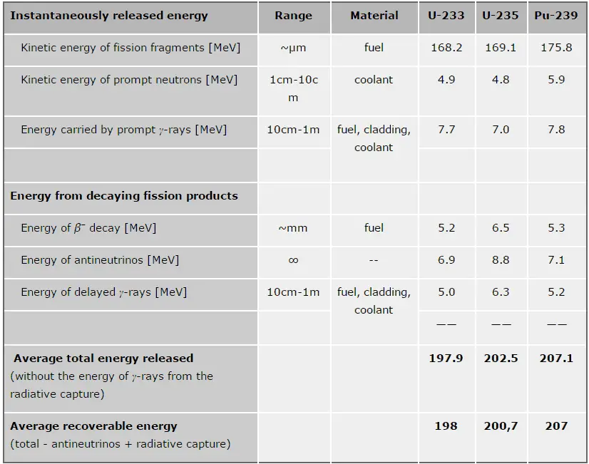 The total energy released in fission can be calculated from binding energies of initial target nucleus to be fissioned and binding energies of fission products. But not all the total energy can be recovered in a reactor. For example, about 10 MeV is released in the form of neutrinos (in fact antineutrinos). Since the neutrinos are weakly interacting (with extremely low cross-section of any interaction), they do not contribute to the energy that can be recovered in a reactor.
As can be seen from the table, the total energy released in a reactor is about 210 MeV per 235U fission, distributed as shown in the table. In a reactor, the average recoverable energy per fission is about 200 MeV, being the total energy minus the energy of the energy of antineutrinos that are radiated away. This means that about 3.1⋅1010 fissions per second are required to produce a power of 1 W. Since 1 gram of any fissile material contains about 2.5 x 10²¹ nuclei, the fissioning of 1 gram of fissile material yields about 1 megawatt-day (MWd) of heat energy.
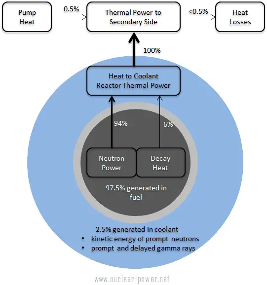
As can be seen from the description of the individual components of the total energy energy released during the fission reaction, there is significant amount of energy generated outside the nuclear fuel (outside fuel rods). Especially the kinetic energy of prompt neutrons is largely generated in the coolant (moderator). This phenomena needs to be included in the nuclear calculations.
For LWR, it is generally accepted that about 2.5% of total energy is recovered in the moderator. This fraction of energy depends on the materials, their arrangement within the reactor, and thus on the reactor type.
It must be also added, also the other reactor internals must be cooled sufficiently in order to prevent overheating of thir construction materials. One of most exposed components is the neutron reflector, especially the heavy reflector. While acting as a neutron shield, the heavy reflector is heated due to absorption of the gamma radiation. In order to avoid overheating, the heat in the reflector is removed by water flowing through cooling channels drilled through the reflector.
See also: Energy release per fission
See also: Residual Heat
 Since the electromagnetic interaction extends over some distance, it is not necessary for the light or heavy charged particle to make a direct collision with an atom. They can transfer energy simply by passing close by. Heavy charged particles, such as fission fragments or alpha particles interact with matter primarily through coulomb forces between their positive charge and the negative charge of the electrons from atomic orbitals. On the other hand, the internal energy of an atom is quantised, therefore only certain amount of energy can be transferred. In general, charged particles transfer energy mostly by:
- Excitation. The charged particle can transfer energy to the atom, raising electrons to a higher energy levels.
- Ionization. Ionization can occur, when the charged particle have enough energy to remove an electron. This results in a creation of ion pairs in surrounding matter.
Creation of pairs requires energy, which is lost from the kinetic energy of the charged particle causing it to decelerate. The positive ions and free electrons created by the passage of the charged particle will then reunite, releasing energy in the form of heat (e.g. vibrational energy or rotational energy of atoms). This is the principle how fission fragments heat up fuel in the reactor core. There are considerable differences in the ways of energy loss and scattering between the passage of light charged particles such as positrons and electrons and heavy charged particles such as fission fragments, alpha particles, muons. Most of these differences are based on the different dynamics of the collision process. In general, when a heavy particle collides with a much lighter particle (electrons in the atomic orbitals), the laws of energy and momentum conservation predict that only a small fraction of the massive particle’s energy can be transferred to the less massive particle. The actual amount of transferred energy depends on how closely the charged particles passes through the atom and it depends also on restrictions from quantisation of energy levels.
The distance required to bring the particle to rest is referred to as its range. The range of fission fragments in solids amounts to only a few microns, and thus most of the energy of fission is converted to heat very close to the point of fission. In case of gases the range increases to a few centimeters in dependence of gas parameters (density, type of gas etc.) The trajectory of heavy charged particles are not greatly affected, because they interacts with light atomic electrons. Other charged particles, such as the alpha particles behave similarly with one exception – for lighter charged particles the ranges are somewhat longer.
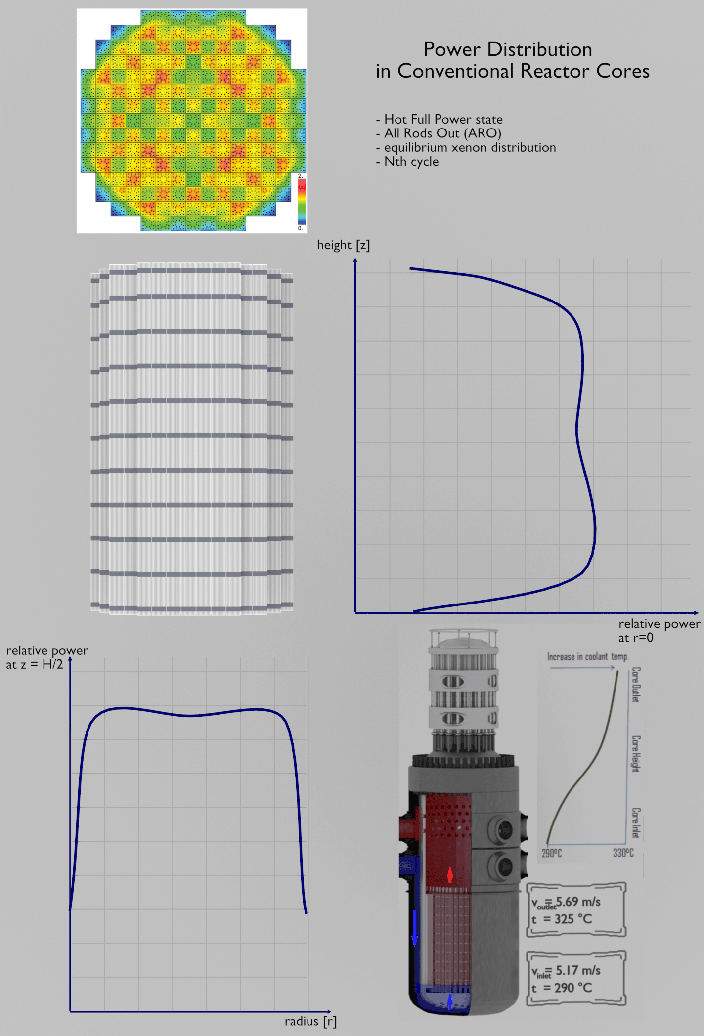
Power Distribution in Conventional Reactor Cores
It should be noted the flux shape derived from the diffusion theory is only a theoretical case in a uniform homogeneous cylindrical reactor at low power levels (at “zero power criticality”). We have implicitly assumed that the core consisting of thousands of fuel and control elements, coolant, and structure can be represented by some effective homogeneous mixture. This is a very strong assumption, because it does not take into account the heterogeneity of a core.
See also: Diffusion Equation – Finite Cylindrical Reactor
In commercial reactor cores the flux distribution is significantly influenced by many factors. One of the most important aspects is the heterogeneity of fuel-moderator assembly. This problem is very complex and is described separately in:
See also: Power Distribution
Thermal Limits
The temperature in an operating reactor varies from point to point within the system. As a consequence, there is always one fuel rod and one local volume, that are hotter than all the rest. In order to limit these hot places the peak power limits must be introduced. The peak power limits are associated with such phenomena as the departure from nucleate boiling and with the conditions which could cause fuel pellet melt.
Therefore power distribution within the core must be properly limited. These limitations are usually divided into two basic categories:
- Limitation of global power distribution
- Limitation of local power distribution
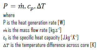
Reactor Coolant delta T – Energy Balance
Another very useful relation is that the thermal power produced by a reactor is directly related to the mass flow rate of the reactor coolant and the temperature difference across the core.
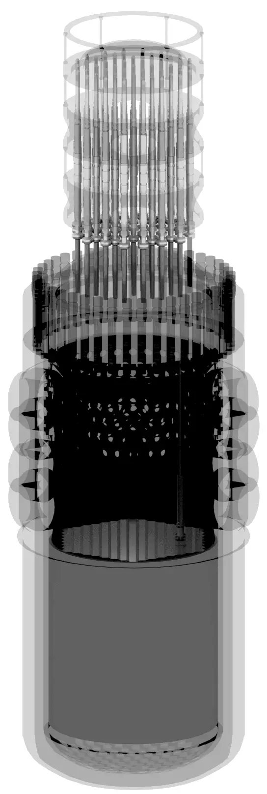
On a straight thermodynamic basis, this heat generation is also related to the fluid temperature difference across the core and the mass flow rate of the fluid passing through the core. Thus, the size of the reactor core is dependent upon and limited by low much liquid can be passed through the core to remove the generated thermal energy. Note that, in PWRs, the core outlet temperature is limited. In a typical pressurized water reactor, the hot primary coolant (water 330°C; 626°F) is pumped into the steam generator through primary inlet. This requires maintaining of very high pressures to keep the water in the liquid state. In order to prevent boiling of the primary coolant and to provide a subcooling margin (the difference between the pressurizer temperature and the highest temperature in the reactor core), pressures around 16 MPa are typical for PWRs. The reactor pressure vessel is the key component, which limits the thermal efficiency of each nuclear power plant, since the reactor vessel must withstand high pressures. Many other factors affect the amount of heat generated within a reactor core, but its limiting generation rate is based upon how much energy can safely be carried away by the coolant.
Temperature Profile – Nuclear Fuel
 See also: Cladding Surface Temperature
Most of PWRs use the uranium fuel, which is in the form of uranium dioxide. Uranium dioxide is a black semiconducting solid with very low thermal conductivity. On the other hand the uranium dioxide has very high melting point and has well known behavior. The UO2 is pressed into cylindrical pellets, these pellets are then sintered into the solid.
These cylindrical pellets are then loaded and encapsulated within a fuel rod (or fuel pin), which is made of zirconium alloys due to its very low absorption cross-section (unlike the stainless steel). The surface of the tube, which covers the pellets, is called fuel cladding.
See also: Thermal Conduction of Uranium Dioxide
Thermal and mechanical behavior of fuel pellets and fuel rods constitute one of three key core design disciplines. Nuclear fuel is operated under very inhospitable conditions (thermal, radiation, mechanical) and must withstand more than normal conditions operation. For example temperatures in the centre of fuel pellets reach more than 1000°C (1832°F) accompanied by fission-gas releases. Therefore detailed knowledge of temperature distribution within a single fuel rod is essential for safe operation of nuclear fuel. In this section we will study heat conduction equation in cylindrical coordinates using Dirichlet boundary condition with given surface temperature (i.e. using Dirichlet boundary condition). Comprehensive analysis of fuel rod temperature profile will be studied in separate section.
Temperature in the centerline of a fuel pellet
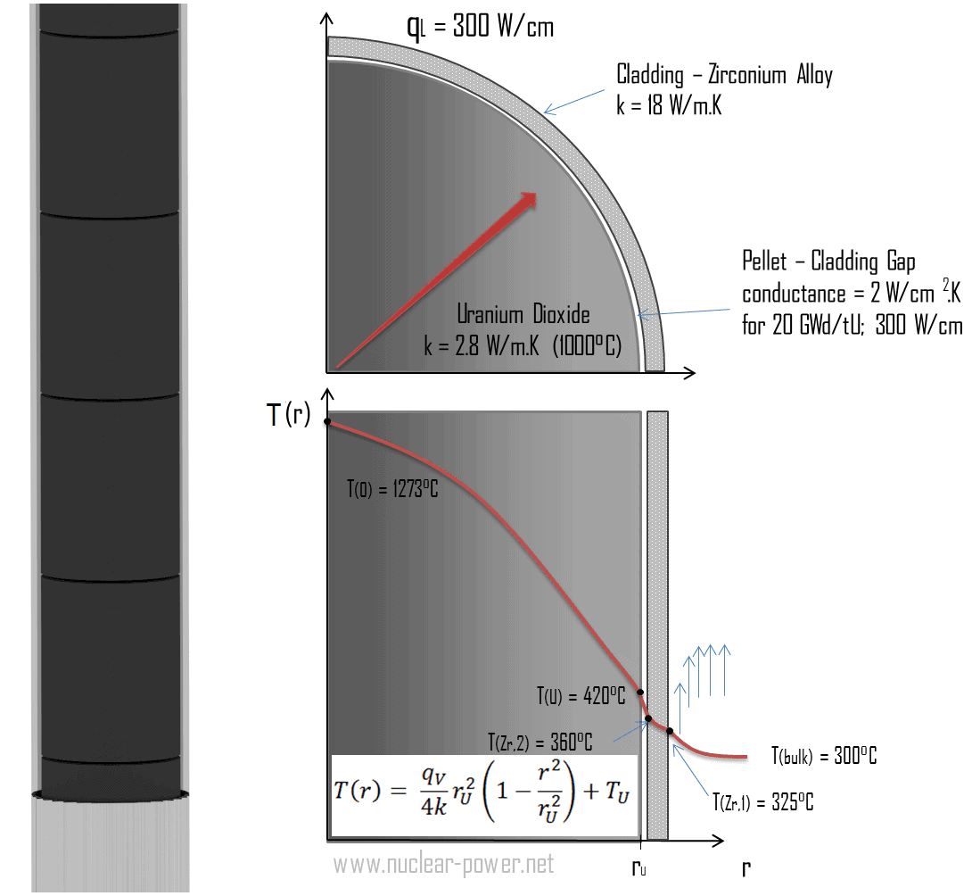
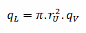
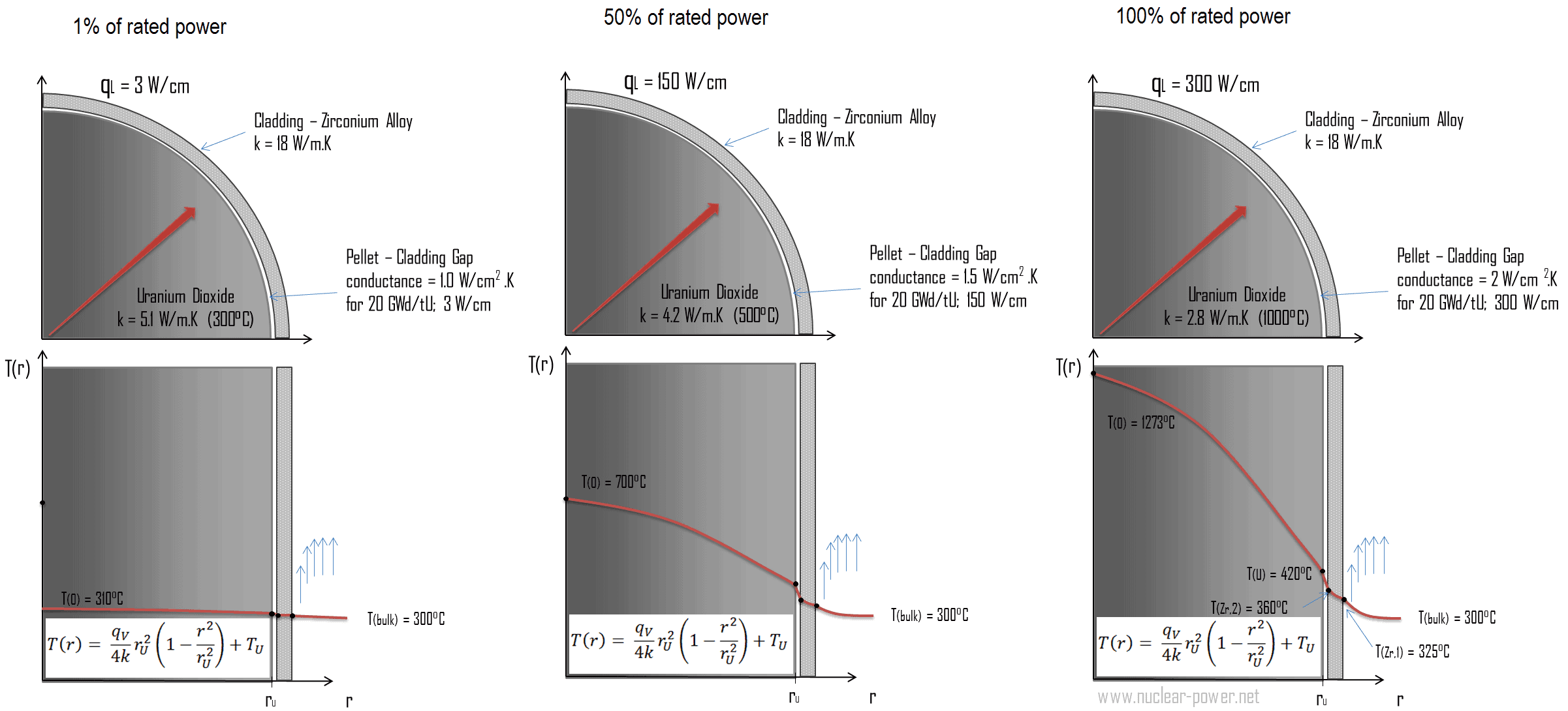
Consider the fuel pellet of radius rU = 0.40 cm, in which there is uniform and constant heat generation per unit volume, qV [W/m3]. Instead of volumetric heat rate qV [W/m3], engineers often use the linear heat rate, qL [W/m], which represents the heat rate of one meter of fuel rod. The linear heat rate can be calculated from the volumetric heat rate by:
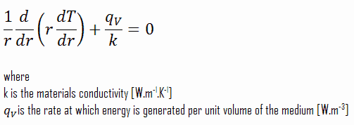
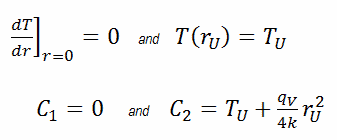
The centreline is taken as the origin for r-coordinate. Due to symmetry in z-direction and in azimuthal direction, we can separate of variables and simplify this problem to one-dimensional problem. Thus, we will solve for the temperature as function of radius, T(r), only. For constant thermal conductivity, k, the appropriate form of the cylindrical heat equation, is:
The general solution of this equation is:
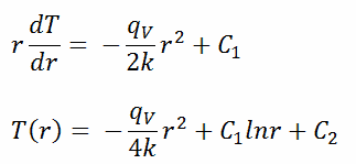
where C1 and C2 are the constants of integration.
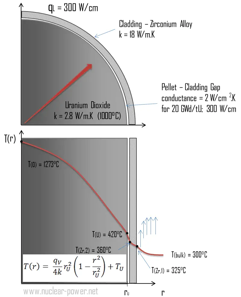 Calculate the temperature distribution, T(r), in this fuel pellet, if:
- the temperatures at the surface of the fuel pellet is TU = 420°C
- the fuel pellet radius rU = 4 mm.
- the averaged material’s conductivity is k = 2.8 W/m.K (corresponds to uranium dioxide at 1000°C)
- the linear heat rate is qL = 300 W/cm and thus the volumetric heat rate is qV = 597 x 106 W/m3
In this case, the surface is maintained at given temperatures TU. This corresponds to the Dirichlet boundary condition. Moreover, this problem is thermally symmetric and therefore we may use also thermal symmetry boundary condition. The constants may be evaluated using substitution into the general solution and are of the form:
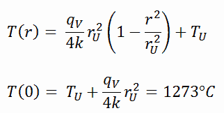
The resulting temperature distribution and the centerline (r = 0) temperature (maximum) in this cylindrical fuel pellet at these specific boundary conditions will be:
The radial heat flux at any radius, qr [W.m-1], in the cylinder may, of course, be determined by using the temperature distribution and with the Fourier’s law. Note that, with heat generation the heat flux is no longer independent of r.
The following figure shows the temperature distribution in the fuel pellet at various power levels.
______
The temperature in an operating reactor varies from point to point within the system. As a consequence, there is always one fuel rod and one local volume, that are hotter than all the rest. In order to limit these hot places the peak power limits must be introduced. The peak power limits are associated with a boiling crisis and with the conditions which could cause fuel pellet melt. However, metallurgical considerations place an upper limits on the temperature of the fuel cladding and the fuel pellet. Above these temperatures there is a danger that the fuel may be damaged. One of the major objectives in the design of a nuclear reactors is to provide for the removal of the heat produced at the desired power level, while assuring that the maximum fuel temperature and the maximum cladding temperature are always below these predetermined values.
We hope, this article, Heat Generation, helps you. If so, give us a like in the sidebar. Main purpose of this website is to help the public to learn some interesting and important information about thermal engineering.