pΔV Work in pV Diagram
Pressure-volume work (or pΔV Work) occurs when the volume V of a system changes. The pΔV Work is equal to the area under the process curve plotted on the pressure-volume diagram. It is known also as the boundary work. Boundary work occurs because the mass of the substance contained within the system boundary causes a force, the pressure times the surface area, to act on the boundary surface and make it move. Boundary work (or pΔV Work) occurs when the volume V of a system changes. It is used for calculating piston displacement work in a closed system. This is what happens when steam, or gas contained in a piston-cylinder device expands against the piston and forces the piston to move.
———–
During the volume change, the pressure and temperature may also change. To calculate such processes, we would need to know how pressure varies with volume for the actual process by which the system changes from state i to state f. The first law of thermodynamics and the work can then be expressed as:
When a thermodynamic system changes from an initial state to a final state, it passes through a series of intermediate states. We call this series of states a path. There are always infinitely many different possibilities for these intermediate states. When they are all equilibrium states, the path can be plotted on a pV-diagram. One of the most important conclusions is that:
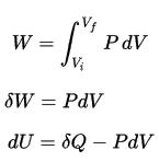
The work done by the system depends not only on the initial and final states, but also on the intermediate states—that is, on the path.
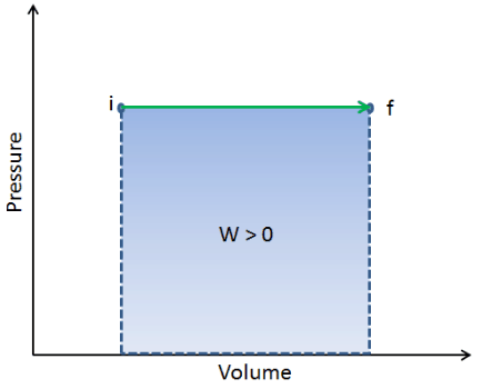
Q and W are path dependent, whereas ΔEint is path independent. As can be seen from the picture (p-V diagram), work is path dependent variable. The blue area represents the pΔV Work done by a system as it goes from an initial state i to a final state f. Work W is positive because the system’s volume increases. The second process shows, that work is greater and that depends on path of the process.
Moreover, we can take the system through a series of states forming a closed loop, such i ⇒ f ⇒ i. In this case the final state is the same as the initial state, but the total work done by the system is not zero. A positive value for work indicates that work is done by the system on its surroundings. A negative value indicates that work is done on the system by its surroundings.
Example: First Law of Thermodynamics and Brayton Cycle
Let assume the ideal Brayton cycle that describes the workings of a constant pressure heat engine. Modern gas turbine engines and airbreathing jet engines also follow the Brayton cycle. This cycle consist of four thermodynamic processes:
-
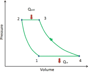
Ideal Brayton cycle consist of four thermodynamic processes. Two isentropic processes and two isobaric processes. isentropic compression – ambient air is drawn into the compressor, where it is pressurized (1 → 2). The work required for the compressor is given by WC = H2 – H1.
- isobaric heat addition – the compressed air then runs through a combustion chamber, where fuel is burned and air or another medium is heated (2 → 3). It is a constant-pressure process, since the chamber is open to flow in and out. The net heat added is given by Qadd = H3 – H2
- isentropic expansion – the heated, pressurized air then expands on turbine, gives up its energy. The work done by turbine is given by WT = H4 – H3
- isobaric heat rejection – the residual heat must be rejected in order to close the cycle. The net heat rejected is given by Qre = H4 – H1

As can be seen, we can describe and calculate (e.g. thermodynamic efficiency) such cycles (similarly for Rankine cycle) using enthalpies.
We hope, this article, pΔV Work in pV Diagram, helps you. If so, give us a like in the sidebar. Main purpose of this website is to help the public to learn some interesting and important information about thermal engineering.