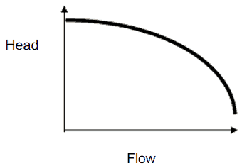
When a centrifugal pump is operating at a constant angular velocity, an increase in the system head (back pressure) on the flowing stream causes a reduction in the volumetric flow rate that the centrifugal pump can maintain.
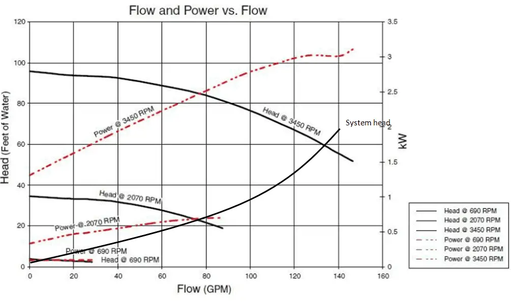
The relationship between the pump head and the volumetric flow rate (Q), that a centrifugal pump can maintain, is dependent on various physical characteristics of the pump as:
- the power supplied to the pump
- the angular velocity of shaft
- the type and diameter of the impeller
and the used fluid:
- fluid density
- fluid viscosity
This relationship is very complicated and its analysis lies in extensive hydraulic testing of certain centrifugal pump. As can be seen from the picture below.
Pump Head Calculation – Pump Performance Calculation
- the design discharge
- water horsepower
- the pump head
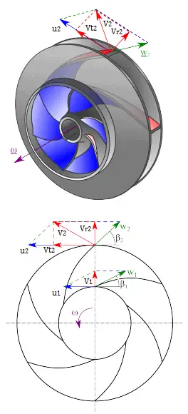
of a centrifugal pump. This performance data will be derived from the Euler’s turbomachine equation:
Shaft torque: Tshaft = ρQ(r2Vt2 – r1Vt1)
Water horsepower: Pw = ω . Tshaft = ρQ(u2Vt2 – u1Vt1)
Pump head: H = Pw / ρgQ = (u2Vt2 – u1Vt1)/g
Given are the following data for a centrifugal water pump:
- diameters of the impeller at the inlet and outlet
- r1 = 10 cm
- r2 = 20 cm
- Speed = 1500 rpm (revolutions per minute)
- the blade angle at inlet β1 = 30°
- the blade angle at outlet β2 = 20°
- assume that the blade widths at inlet and outlet are: b1 = b2 = 4 cm.
Solution:
First, we have to calculate the radial velocity of the flow at the outlet. From the velocity diagram the radial velocity is equal to (we assume that the flow enters exactly normal to the impeller, so tangential component of velocity is zero):
Vr1 = u1 tan 30° = ω r1 tan 30° = 2π x (1500/60) x 0.1 x tan 30° = 9.1 m/s
Radial component of flow velocity determines how much the volume flow rate is entering the impeller. So when we know Vr1 at inlet, we can determine the discharge of this pump according to following equation. Here b1 means the blade width of the impeller at inlet.
Q = 2π.r1.b1.Vr1 = 2π x 0.1 x 0.04 x 9.1 = 0.229 m3/s
In order to calculate the water horsepower (Pw) required, we have to determine the outlet tangential flow velocity Vt2, because it has been assumed that the inlet tangential velocity Vt1 is equal to zero.
The outlet radial flow velocity follows from conservation of Q:
Q = 2π.r2.b2.Vr2 ⇒ Vr2 = Q / 2π.r2.b2 = 0.229 / (2π x 0.2 x 0.04) = 4.56 m/s
From the figure (velocity triangle) outlet blade angle, β2, can be easily represented as follows.
cot β2 = (u2 – Vt2) / Vr2
and therefore the outlet tangential flow velocity Vt2 is:
Vt2 = u2 – Vr2 . cot 20° = ω r2 – Vr2 . cot 20° = 2π x 1500/60 x 0.2 – 4.56 x 2.75 = 31.4 – 12.5 = 18.9 m/s.
The water horsepower required is then:
Pw = ρ Q u2 Vt2 = 1000 [kg/m3] x 0.229 [m3/s] x 31.4 [m/s] x 18.9 [m/s] = 135900 W = 135.6 kW
and the pump head is:
H ≈ Pw / (ρ g Q) = 135900 / (1000 x 9.81 x 0.229) = 60.5 m
We hope, this article, Pump Head Calculation – Pump Performance Calculation, helps you. If so, give us a like in the sidebar. Main purpose of this website is to help the public to learn some interesting and important information about thermal engineering.