The friction factor has been determined to depend on the Reynolds number for the flow and the degree of roughness of the pipe’s inner surface (especially for turbulent flow). The friction factor of laminar flow is independent of roughness of the pipe’s inner surface.
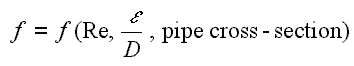
The pipe cross-section is also important, as deviations from circular cross-section will cause secondary flows that increase the head loss. Non-circular pipes and ducts are generally treated by using the hydraulic diameter.
Relative Roughness
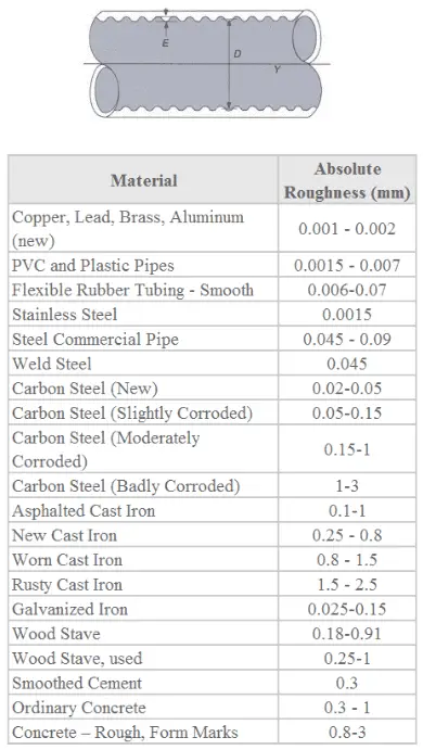
The quantity used to measure the roughness of the pipe’s inner surface is called the relative roughness, and it is equal to the average height of surface irregularities (ε) divided by the pipe diameter (D).
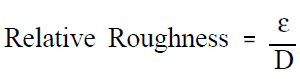
,where both the average height surface irregularities and the pipe diameter are in millimeters.
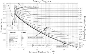
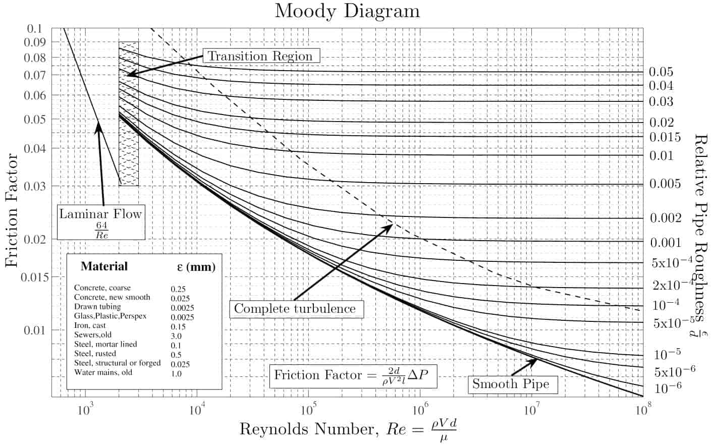
If we know the relative roughness of the pipe’s inner surface, then we can obtain the value of the friction factor from the Moody Chart.
The Moody chart (also known as the Moody diagram) is a graph in non-dimensional form that relates the Darcy friction factor, Reynolds number, and the relative roughness for fully developed flow in a circular pipe.
Summary:
- Head loss of hydraulic system is divided into two main categories:
- Major Head Loss – due to friction in straight pipes
- Minor Head Loss – due to components as valves, bends…
- Darcy’s equation can be used to calculate major losses.
- The friction factor for fluid flow can be determined using a Moody chart.
- The friction factor for laminar flow is independent of roughness of the pipe’s inner surface. f = 64/Re
- The friction factor for turbulent flow depends strongly on the relative roughness. It is determined by the Colebrook equation. It must be noted, at very large Reynolds numbers, the friction factor is independent of the Reynolds number.
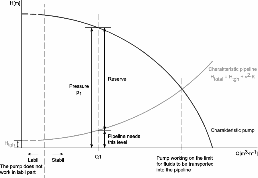
Why the head loss is very important?
As can be seen from the picture, the head loss is forms key characteristic of any hydraulic system. In systems, in which some certain flowrate must be maintained (e.g. to provide sufficient cooling or heat transfer from a reactor core), the equilibrium of the head loss and the head added by a pump determines the flowrate through the system.
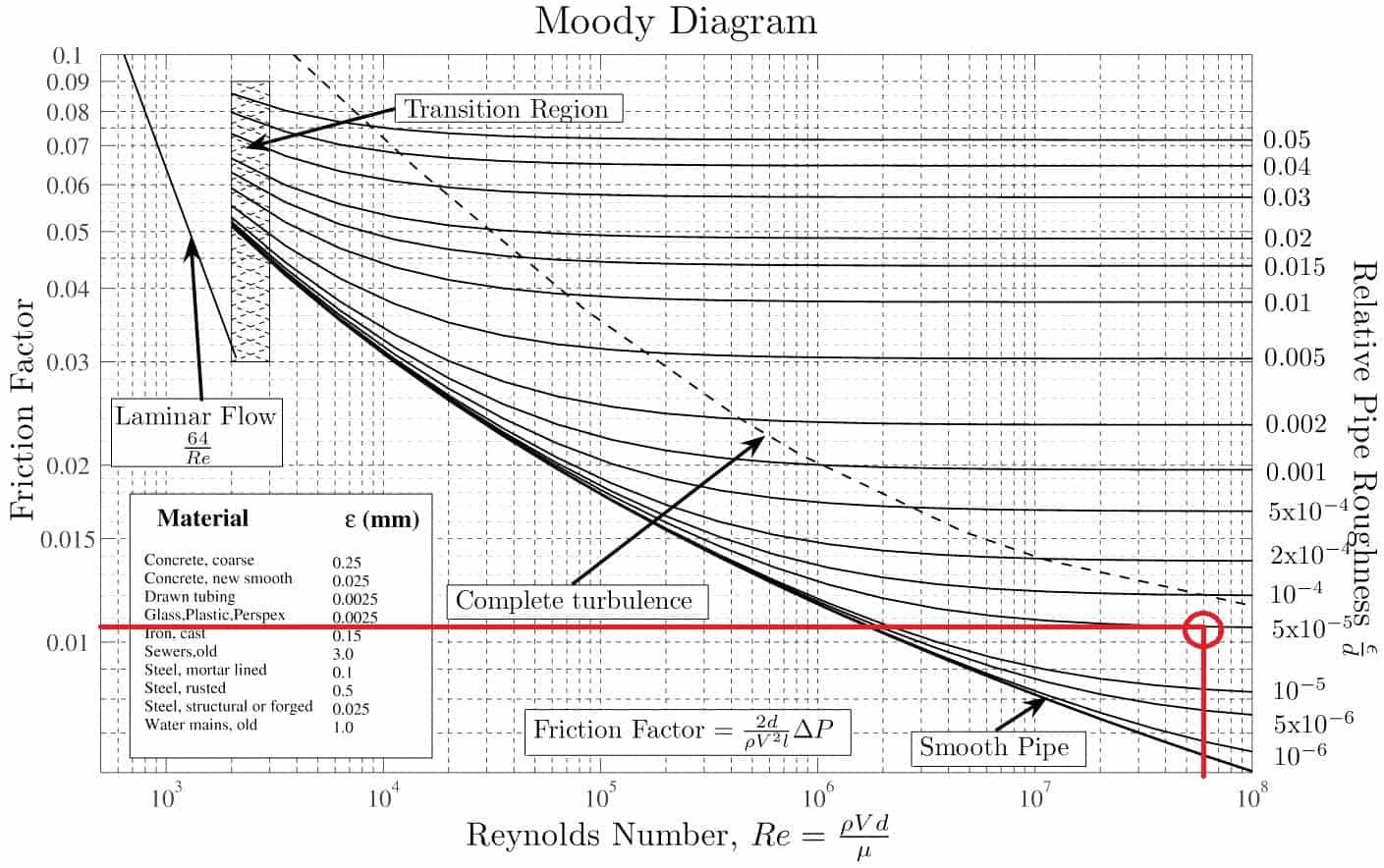
Solution:
The relative roughness is equal to ε = 0.035 / 700 = 5 x 10⁻⁵. Using the Moody Chart, a Reynolds number of 50 000 000 intersects the curve corresponding to a relative roughness of 5 x 10⁻⁵ at a friction factor of 0.011.
Source: Donebythesecondlaw at the English language Wikipedia, CC BY-SA 3.0, https://commons.wikimedia.org/w/index.php?curid=4681366
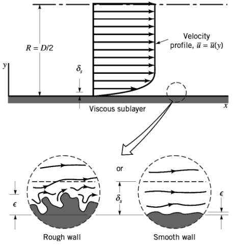 It must be noted, at very large Reynolds numbers, the friction factor is independent of the Reynolds number. This is because the thickness of laminar sublayer (viscous sublayer) decreases with increasing Reynolds number. For very large Reynolds numbers the thickness of laminar sublayer is comparable to the surface roughness and it directly influences the flow. The laminar sublayer becomes so thin that the surface roughness protrudes into the flow. The frictional losses in this case are produced in the main flow primarily by the protruding roughness elements, and the contribution of the laminar sublayer is negligible.
We hope, this article, Relative Roughness of Pipe, helps you. If so, give us a like in the sidebar. Main purpose of this website is to help the public to learn some interesting and important information about thermal engineering.