Heat Exchangers
Heat exchangers are devices that are used to transfer thermal energy from one fluid to another without mixing the two fluids. The fluids are usually separated by a solid wall (with high thermal conductivity) to prevent mixing or they may be in direct contact.
The classic example of a heat exchanger is found in an internal combustion engine in which an engine coolant flows through radiator coils and air flows past the coils, which cools the coolant and heats the incoming air. In power engineering, common applications of heat exchangers include steam generators, fan coolers, cooling water heat exchangers, and condensers. For example, steam generator is used to convert feedwater into steam from heat produced in a nuclear reactor core. The steam produced drives the turbine.
Heat transfer in a heat exchanger usually involves convection in each fluid and thermal conduction through the wall separating the two fluids. In the analysis of heat exchangers, it is often convenient to work with an overall heat transfer coefficient, known as a U-factor. The U-factor is defined by an expression analogous to Newton’s law of cooling.
Moreover, engineers also use the logarithmic mean temperature difference (LMTD) to determine the temperature driving force for heat transfer in heat exchangers.
Special Reference: John R. Thome, Engineering Data Book III. Wolverine Tube Inc. 2004.
Types of Heat Exchangers – Classification of Heat Exchangers
Heat exchangers are typically classified according to flow arrangement and type of construction. The simplest heat exchanger is one for which the hot and cold fluids move in the same or opposite directions. This heat exchanger consists of two concentric pipes of different diameters.
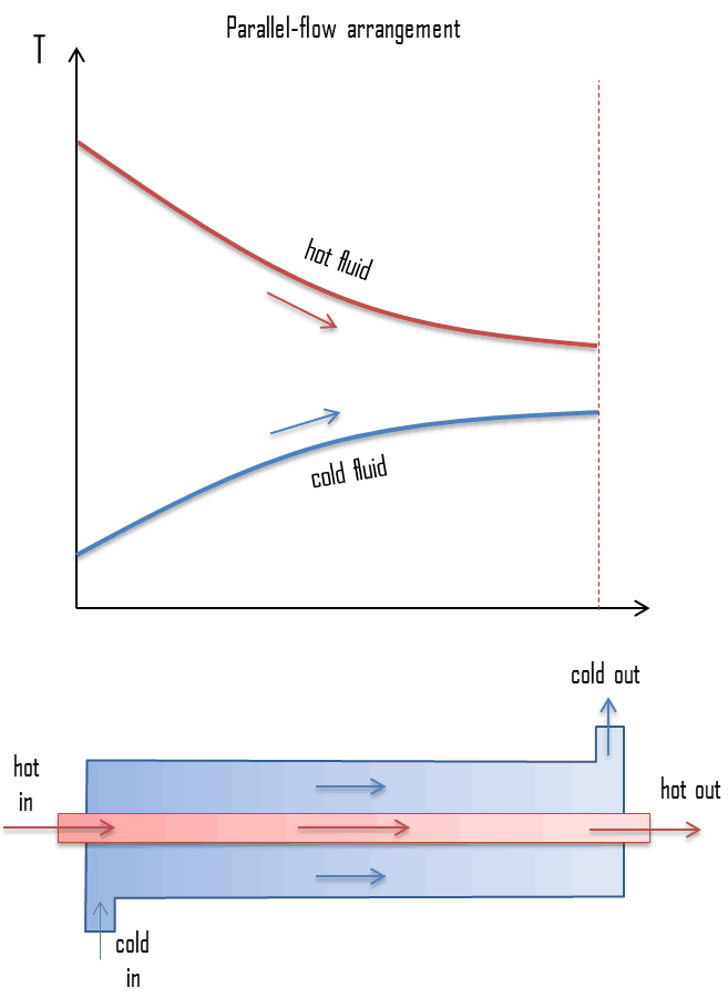
- parallel-flow arrangement. In the parallel-flow arrangement, the hot and cold fluids enter at the same end, flow in the same direction, and leave at the same end.
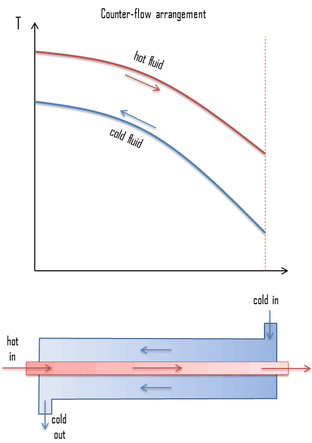
- counter-flow arrangement. In the counter-flow arrangement, the fluids enter at opposite ends, flow in opposite directions, and leave at opposite ends.
Figure represents the directions of fluid flow in the parallel and counter-flow exchangers. Under comparable conditions, more heat is transferred in a counter-flow arrangement than in a parallel flow heat exchanger. The temperature profiles of the two heat exchangers indicate two major disadvantages in the parallel-flow design.
- The large temperature difference at the ends causes large thermal stresses.
- The temperature of the cold fluid exiting the heat exchanger never exceeds the lowest temperature of the hot fluid.
The design of a parallel flow heat exchanger is advantageous when two fluids are required to be brought to nearly the same temperature.
- Double pipe heat exchangers. Double pipe heat exchangers are cheap for both design and maintenance, making them a good choice for small industries. In these exchangers one fluid flows inside the tube and the other fluid flows on the outside. Although they are simple and cheap, their low efficiency coupled with the high space occupied in large scales, has led modern industries to use more efficient heat exchangers like shell and tube.
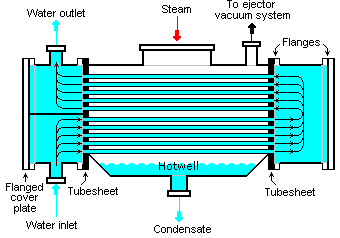
- Shell and tube heat exchangers. Shell and tube heat exchangers in their various construction modifications are probably the most widespread and commonly used basic heat exchanger configuration in industry. Shell-and-tube heat exchangers are further classified according to the number of shell and tube passes involved. Shell and tube heat exchangers are typically used for high-pressure applications (with pressures greater than 30 bar and temperatures greater than 260 °C). This is because the shell and tube heat exchangers can withstand high pressures due to their shape. In this type of heat exchanger, a number of small bore pipes are fitted between two tube plates and primary fluid flows through these tubes. The tube bundle is placed inside a shell and the secondary fluid flows through the shell and over the surface of the tubes. In nuclear engineering, this design of heat exchangers is widely used as in case of steam generator, which are used to convert feedwater into steam from heat produced in a nuclear reactor core. To increase the amount of heat transferred and the power generated, the heat exchange surface must be maximized. This is obtained by using tubes. Each steam generator can contain anywhere from 3,000 to 16,000 tubes, each about 19mm diameter.
- Plate heat exchangers. A plate heat exchanger is a type of heat exchanger that uses metal plates to transfer heat between two fluids. This arrangement is popular with heat exchangers using air or gas as well as lower velocity fluid flow. The classic example of a heat exchanger is found in an internal combustion engine in which an engine coolant flows through radiator coils and air flows past the coils, which cools the coolant and heats the incoming air. When compared to shell and tube exchangers, the stacked-plate arrangement typically has lower volume and cost. Another difference between the two is that plate exchangers typically serve low to medium pressure fluids, compared to medium and high pressures of shell and tube.
We hope, this article, Type of Heat Exchangers – Classification of Heat Exchangers, helps you. If so, give us a like in the sidebar. Main purpose of this website is to help the public to learn some interesting and important information about thermal engineering.