Carnot Cycle – Carnot Heat Engine
The second law of thermodynamics places constraints upon the direction of heat transfer and sets an upper limit to the efficiency of conversion of heat to work in heat engines. So the second law is directly relevant for many important practical problems.
In 1824, a French engineer and physicist, Nicolas Léonard Sadi Carnot advanced the study of the second law by forming a principle (also called Carnot’s rule) that specifies limits on the maximum efficiency any heat engine can obtain. In short, this principle states that the efficiency of a thermodynamic cycle depends solely on the difference between the hot and cold temperature reservoirs.
Carnot’s principle states:
- No engine can be more efficient than a reversible engine (a Carnot heat engine) operating between the same high temperature and low temperature reservoirs.
- The efficiencies of all reversible engines (Carnot heat engines) operating between the same constant temperature reservoirs are the same, regardless of the working substance employed or the operation details.
The cycle of this engine is called the Carnot cycle. A system undergoing a Carnot cycle is called a Carnot heat engine. It is not an actual thermodynamic cycle but is a theoretical construct and cannot be built in practice. All real thermodynamic processes are somehow irreversible. They are not done infinitely slowly and infinitesimally small steps in temperature are also a theoretical fiction. Therefore, heat engines must have lower efficiencies than limits on their efficiency due to the inherent irreversibility of the heat engine cycle they use.
Carnot Cycle – Processes
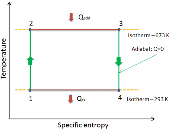
- isentropic compression – The gas is compressed adiabatically from state 1 to state 2, where the temperature is TH. The surroundings do work on the gas, increasing its internal energy and compressing it. On the other hand the entropy remains unchanged.
- Isothermal expansion – The system is placed in contact with the reservoir at TH. The gas expands isothermally while receiving energy QH from the hot reservoir by heat transfer. The temperature of the gas does not change during the process. The gas does work on the surroundings. The total entropy change is given by: ∆S = S1 – S4 = QH/TH
- isentropic expansion – The gas expands adiabatically from state 3 to state 4, where the temperature is TC. The gas does work on the surroundings and loses an amount of internal energy equal to the work that leaves the system. Again the entropy remains unchanged.
- isothermal compression – The system is placed in contact with the reservoir at TC. The gas compresses isothermally to its initial state while it discharges energy QC to the cold reservoir by heat transfer. In this process the surroundings do work on the gas. The total entropy change is given by: ∆S = S3 – S2 = QC/TC
Isentropic Process
An isentropic process is a thermodynamic process, in which the entropy of the fluid or gas remains constant. It means the isentropic process is a special case of an adiabatic process in which there is no transfer of heat or matter. It is a reversible adiabatic process. The assumption of no heat transfer is very important, since we can use the adiabatic approximation only in very rapid processes.
Isentropic Process and the First Law
For a closed system, we can write the first law of thermodynamics in terms of enthalpy:
dH = dQ + Vdp
or
dH = TdS + Vdp
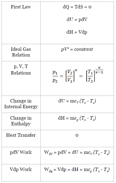
Isentropic process (dQ = 0):
dH = Vdp → W = H2 – H1 → H2 – H1 = Cp (T2 – T1) (for ideal gas)
Isentropic Process of the Ideal Gas
The isentropic process (a special case of adiabatic process) can be expressed with the ideal gas law as:
pVκ = constant
or
p1V1κ = p2V2κ
in which κ = cp/cv is the ratio of the specific heats (or heat capacities) for the gas. One for constant pressure (cp) and one for constant volume (cv). Note that, this ratio κ = cp/cv is a factor in determining the speed of sound in a gas and other adiabatic processes.
Isothermal Process
An isothermal process is a thermodynamic process, in which the temperature of the system remains constant (T = const). The heat transfer into or out of the system typically must happen at such a slow rate in order to continually adjust to the temperature of the reservoir through heat exchange. In each of these states the thermal equilibrium is maintained.
Isothermal Process and the First Law
The classical form of the first law of thermodynamics is the following equation:
dU = dQ – dW
In this equation dW is equal to dW = pdV and is known as the boundary work.
In isothermal process and the ideal gas, all heat added to the system will be used to do work:
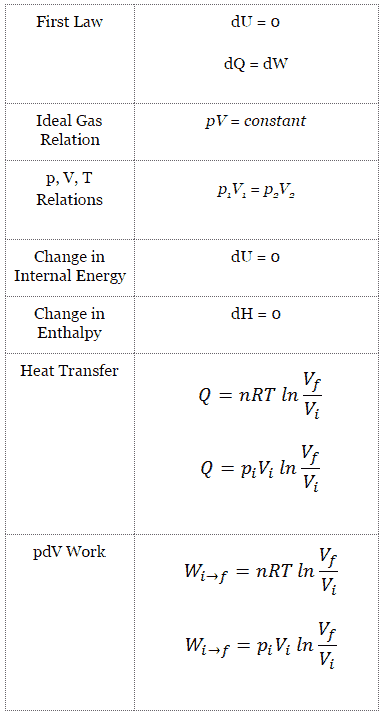
Isothermal process (dU = 0):
dU = 0 = Q – W → W = Q (for ideal gas)
Isothermal Process of the Ideal Gas
The isothermal process can be expressed with the ideal gas law as:
pV = constant
or
p1V1 = p2V2
On a p-V diagram, the process occurs along a line (called an isotherm) that has the equation p = constant / V.
See also: Boyle-Mariotte Law
Carnot Cycle – pV, Ts diagram
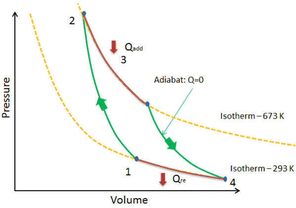
The Carnot cycle is often plotted on a pressure- volume diagram (pV diagram) and on a temperature-entropy diagram (Ts diagram).
When plotted on a pressure-volume diagram, the isothermal processes follow the isotherm lines for the gas, adiabatic processes move between isotherms and the area bounded by the complete cycle path represents the total work that can be done during one cycle.
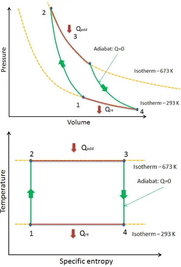
The temperature-entropy diagram (Ts diagram) in which the thermodynamic state is specified by a point on a graph with specific entropy (s) as the horizontal axis and absolute temperature (T) as the vertical axis, is the best diagram to describe behaviour of a Carnot cycle.
It is a useful and common tool, particularly because it helps to visualize the heat transfer during a process. For reversible (ideal) processes, the area under the T-s curve of a process is the heat transferred to the system during that process.
Carnot Cycle Efficiency
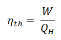
In general, the thermal efficiency, ηth, of any heat engine is defined as the ratio of the net work it does, W, to the heat input at the high temperature, QH.
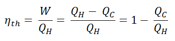
Since energy is conserved according to the first law of thermodynamics and energy cannot be be converted to work completely, the heat input, QH, must equal the work done, W, plus the heat that must be dissipated as waste heat QC into the environment. Therefore we can rewrite the formula for thermal efficiency as:
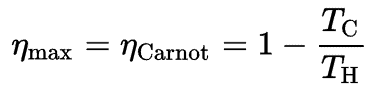
Since QC = ∆S.TC and QH = ∆S.TH, the formula for this maximum efficiency is:
where:
- is the efficiency of Carnot cycle, i.e. it is the ratio = W/QH of the work done by the engine to the heat energy entering the system from the hot reservoir.
- TC is the absolute temperature (Kelvins) of the cold reservoir,
- TH is the absolute temperature (Kelvins) of the hot reservoir.
See also : Causes of Inefficiencies
Example: Carnot efficiency for coal-fired power plant
In a modern coal-fired power plant, the temperature of high pressure steam (Thot) would be about 400°C (673K) and Tcold, the cooling tower water temperature, would be about 20°C (293K). For this type of power plant the maximum (ideal) efficiency will be:
ηth= 1 – Tcold/Thot = 1 – 293/673 = 56%
It must be added, this is an idealized efficiency. The Carnot efficiency is valid for reversible processes. These processes cannot be achieved in real cycles of power plants. The Carnot efficiency dictates that higher efficiencies can be attained by increasing the temperature of the steam. This feature is valid also for real thermodynamic cycles. But this requires an increase in pressures inside boilers or steam generators. However, metallurgical considerations place an upper limits on such pressures. Sub-critical fossil fuel power plants, that are operated under critical pressure (i.e. lower than 22.1 MPa), can achieve 36–40% efficiency. Supercritical designs, that are operated at supercritical pressure (i.e. greater than 22.1 MPa), have efficiencies around 43%. Most efficient and also very complex coal-fired power plants that are operated at “ultra critical” pressures (i.e. around 30 MPa) and use multiple stage reheat reach about 48% efficiency.
See also: Supercritical Reactor
We hope, this article, Carnot Cycle – Carnot Heat Engine, helps you. If so, give us a like in the sidebar. Main purpose of this website is to help the public to learn some interesting and important information about thermal engineering.