Facebook Instagram Youtube Twitter

What is Thermal Conductivity of Zirconium – Definition

Thermal Conductivity of Zirconium. Zirconium alloys have lower thermal conductivity (about 18 W/m.K) than pure zirconium metal (about 22 W/m.K). Thermal Engineering

Thermal Conductivity of Zirconium
Thermal conduction - thermal conductivity - zirconium

Thermal Conductivity of Zirconium

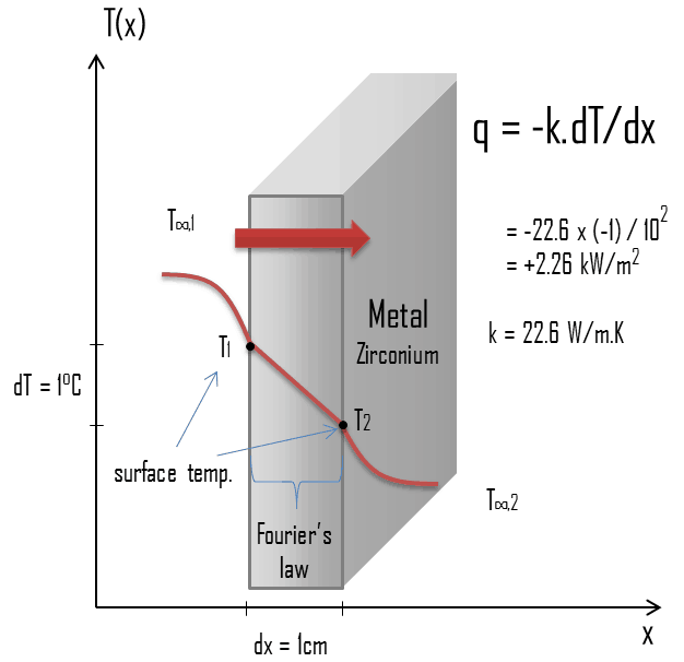
Zirconium is a lustrous, grey-white, strong transition metal that resembles hafnium and, to a lesser extent, titanium. Zirconium is mainly used as a refractory and opacifier, although small amounts are used as an alloying agent for its strong resistance to corrosion. Zirconium alloy (e.g. Zr + 1%Nb) is widely used as a cladding for nuclear reactor fuels. The desired properties of these alloys are a low neutron-capture cross-section and resistance to corrosion under normal service conditions. Zirconium alloys have lower thermal conductivity (about 18 W/m.K) than pure zirconium metal (about 22 W/m.K).

Special reference: Thermophysical Properties of Materials For Nuclear Engineering: A Tutorial and Collection of Data. IAEA-THPH, IAEA, Vienna, 2008. ISBN 978–92–0–106508–7.

Thermal Conductivity of Metals
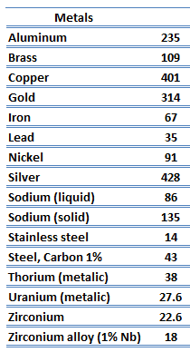
thermal conductivity - metalsMetals are solids and as such they possess crystalline structure where the ions (nuclei with their surrounding shells of core electrons) occupy translationally equivalent positions in the crystal lattice. Metals in general have high electrical conductivity, high thermal conductivity, and high density. Accordingly, transport of thermal energy may be due to two effects:

  • the migration of free electrons
  • lattice vibrational waves (phonons).

When electrons and phonons carry thermal energy leading to conduction heat transfer in a solid, the thermal conductivity may be expressed as:

k = ke + kph

The unique feature of metals as far as their structure is concerned is the presence of charge carriers, specifically electrons. The electrical and thermal conductivities of metals originate from the fact that their outer electrons are delocalized. Their contribution to the thermal conductivity is referred to as the electronic thermal conductivity, ke. In fact, in pure metals such as gold, silver, copper, and aluminum, the heat current associated with the flow of electrons by far exceeds a small contribution due to the flow of phonons. In contrast, for alloys, the contribution of kph to k is no longer negligible.

 
References:
Heat Transfer:
  1. Fundamentals of Heat and Mass Transfer, 7th Edition. Theodore L. Bergman, Adrienne S. Lavine, Frank P. Incropera. John Wiley & Sons, Incorporated, 2011. ISBN: 9781118137253.
  2. Heat and Mass Transfer. Yunus A. Cengel. McGraw-Hill Education, 2011. ISBN: 9780071077866.
  3. Fundamentals of Heat and Mass Transfer. C. P. Kothandaraman. New Age International, 2006, ISBN: 9788122417722.
  4. U.S. Department of Energy, Thermodynamics, Heat Transfer and Fluid Flow. DOE Fundamentals Handbook, Volume 2 of 3. May 2016.

Nuclear and Reactor Physics:

  1. J. R. Lamarsh, Introduction to Nuclear Reactor Theory, 2nd ed., Addison-Wesley, Reading, MA (1983).
  2. J. R. Lamarsh, A. J. Baratta, Introduction to Nuclear Engineering, 3d ed., Prentice-Hall, 2001, ISBN: 0-201-82498-1.
  3. W. M. Stacey, Nuclear Reactor Physics, John Wiley & Sons, 2001, ISBN: 0- 471-39127-1.
  4. Glasstone, Sesonske. Nuclear Reactor Engineering: Reactor Systems Engineering, Springer; 4th edition, 1994, ISBN: 978-0412985317
  5. W.S.C. Williams. Nuclear and Particle Physics. Clarendon Press; 1 edition, 1991, ISBN: 978-0198520467
  6. G.R.Keepin. Physics of Nuclear Kinetics. Addison-Wesley Pub. Co; 1st edition, 1965
  7. Robert Reed Burn, Introduction to Nuclear Reactor Operation, 1988.
  8. U.S. Department of Energy, Nuclear Physics and Reactor Theory. DOE Fundamentals Handbook, Volume 1 and 2. January 1993.
  9. Paul Reuss, Neutron Physics. EDP Sciences, 2008. ISBN: 978-2759800414.

Advanced Reactor Physics:

  1. K. O. Ott, W. A. Bezella, Introductory Nuclear Reactor Statics, American Nuclear Society, Revised edition (1989), 1989, ISBN: 0-894-48033-2.
  2. K. O. Ott, R. J. Neuhold, Introductory Nuclear Reactor Dynamics, American Nuclear Society, 1985, ISBN: 0-894-48029-4.
  3. D. L. Hetrick, Dynamics of Nuclear Reactors, American Nuclear Society, 1993, ISBN: 0-894-48453-2.
  4. E. E. Lewis, W. F. Miller, Computational Methods of Neutron Transport, American Nuclear Society, 1993, ISBN: 0-894-48452-4.

See also:

Thermal Conductivity

We hope, this article, Thermal Conductivity of Zirconium, helps you. If so, give us a like in the sidebar. Main purpose of this website is to help the public to learn some interesting and important information about thermal engineering.

What is Thermal Conductivity of Glass – Definition

Thermal Conductivity of Glass. Since glass is an amorphous solid material, it has not high thermal conductivity. Its thermal conductivity is about k = 1 W/m.K. Thermal Engineering

Thermal Conductivity of Glass

Glass is a non-crystalline amorphous solid that is often transparent and has widespread practical, technological, and decorative usage in, for example, window panes. Glass is made of sand and other minerals that are melted together at very high temperatures to form a material that is ideal for a wide range of uses. Since it is an amorphous solid material, it has not high thermal conductivity. Its thermal conductivity is about k = 1 W/m.K.

Example – Heat flux through a window

Example - Heat Flux - Thermal ConductionHeat loss through windows

A major source of heat loss from a house is through the windows. Calculate the rate of heat flux through a glass window 1.5 m x 1.0 m in area and 3.0 mm thick, if the temperatures at the inner and outer surfaces are 14.0°C and 13.0°C, respectively. Calculate the heat flux through this window.

Solution:

At this point, we know the temperatures at the surfaces of material. These temperatures are given also by conditions inside the house and outside the house. In this case, heat flows by conduction through the glass from the higher inside temperature to the lower outside temperature. We use the heat conduction equation:

Heat loss through window - equation

We assume that the thermal conductivity of a common glass is k = 0.96 W/m.K.

The heat flux will then be:

q = 0.96 [W/m.K] x 1 [K] / 3.0 x 10-3 [m] = 320 W/m2

The total heat loss through this window will be:

qloss = q . A = 320 x 1.5 x 1.0 = 480W

Thermal Conductivity of Nonmetals

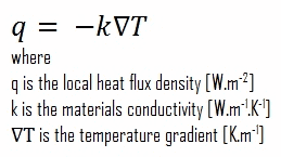
thermal conductivity - building materialsFor nonmetallic solids, k is determined primarily by kph, which increases as the frequency of interactions between the atoms and the lattice decreases. In fact, lattice thermal conduction is the dominant thermal conduction mechanism in nonmetals, if not the only one. In solids, atoms vibrate about their equilibrium positions (crystal lattice). The vibrations of atoms are not independent of each other, but are rather strongly coupled with neighboring atoms. The regularity of the lattice arrangement has an important effect on kph, with crystalline (well-ordered) materials like quartz having a higher thermal conductivity than amorphous materials like glass. At sufficiently high temperatures kph ∝ 1/T.

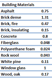
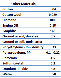
thermal conductivity - solidsThe quanta of the crystal vibrational field are referred to as ‘‘phonons.’’ A phonon is a collective excitation in a periodic, elastic arrangement of atoms or molecules in condensed matter, like solids and some liquids. Phonons play a major role in many of the physical properties of condensed matter, like thermal conductivity and electrical conductivity. In fact, for crystalline, nonmetallic solids such as diamond, kph can be quite large, exceeding values of k associated with good conductors, such as aluminum. In particular, diamond has the highest hardness and thermal conductivity (k = 1000 W/m.K) of any bulk material.

 
References:
Heat Transfer:
  1. Fundamentals of Heat and Mass Transfer, 7th Edition. Theodore L. Bergman, Adrienne S. Lavine, Frank P. Incropera. John Wiley & Sons, Incorporated, 2011. ISBN: 9781118137253.
  2. Heat and Mass Transfer. Yunus A. Cengel. McGraw-Hill Education, 2011. ISBN: 9780071077866.
  3. Fundamentals of Heat and Mass Transfer. C. P. Kothandaraman. New Age International, 2006, ISBN: 9788122417722.
  4. U.S. Department of Energy, Thermodynamics, Heat Transfer and Fluid Flow. DOE Fundamentals Handbook, Volume 2 of 3. May 2016.

Nuclear and Reactor Physics:

  1. J. R. Lamarsh, Introduction to Nuclear Reactor Theory, 2nd ed., Addison-Wesley, Reading, MA (1983).
  2. J. R. Lamarsh, A. J. Baratta, Introduction to Nuclear Engineering, 3d ed., Prentice-Hall, 2001, ISBN: 0-201-82498-1.
  3. W. M. Stacey, Nuclear Reactor Physics, John Wiley & Sons, 2001, ISBN: 0- 471-39127-1.
  4. Glasstone, Sesonske. Nuclear Reactor Engineering: Reactor Systems Engineering, Springer; 4th edition, 1994, ISBN: 978-0412985317
  5. W.S.C. Williams. Nuclear and Particle Physics. Clarendon Press; 1 edition, 1991, ISBN: 978-0198520467
  6. G.R.Keepin. Physics of Nuclear Kinetics. Addison-Wesley Pub. Co; 1st edition, 1965
  7. Robert Reed Burn, Introduction to Nuclear Reactor Operation, 1988.
  8. U.S. Department of Energy, Nuclear Physics and Reactor Theory. DOE Fundamentals Handbook, Volume 1 and 2. January 1993.
  9. Paul Reuss, Neutron Physics. EDP Sciences, 2008. ISBN: 978-2759800414.

Advanced Reactor Physics:

  1. K. O. Ott, W. A. Bezella, Introductory Nuclear Reactor Statics, American Nuclear Society, Revised edition (1989), 1989, ISBN: 0-894-48033-2.
  2. K. O. Ott, R. J. Neuhold, Introductory Nuclear Reactor Dynamics, American Nuclear Society, 1985, ISBN: 0-894-48029-4.
  3. D. L. Hetrick, Dynamics of Nuclear Reactors, American Nuclear Society, 1993, ISBN: 0-894-48453-2.
  4. E. E. Lewis, W. F. Miller, Computational Methods of Neutron Transport, American Nuclear Society, 1993, ISBN: 0-894-48452-4.

See also:

Thermal Conductivity

We hope, this article, Thermal Conductivity of Glass, helps you. If so, give us a like in the sidebar. Main purpose of this website is to help the public to learn some interesting and important information about thermal engineering.
What is Thermal Resistance – Thermal Resistivity – Definition

Thermal resistance is a heat property and a measurement of a temperature difference by which an object or material resists a heat flow. Thermal Resistivity

Thermal Resistance – Thermal Resistivity

thermal resistance - definition - analogyIn engineering, another very important concept is often used. Since there is an analogy between the diffusion of heat and electrical charge, engineers often use the thermal resistance (i.e. thermal resistance against heat conduction) to calculate heat transfer through materials. Thermal resistance is the reciprocal of thermal conductance. Just as an electrical resistance is associated with the conduction of electricity, a thermal resistance may be associated with the conduction of heat.

Consider a plane wall of thickness L and average thermal conductivity k. The two surfaces of the wall are maintained at constant temperatures of T1 and T2. For one-dimensional steady heat conduction through the wall, we have T(x). Then Fourier’s law of heat conduction for the wall can be expressed as:

Fourier’s law with thermal resistance

Definition of Thermal Resistance

Thermal resistance is a heat property and a measurement of a temperature difference by which an object or material resists a heat flow. The thermal resistance for conduction in a plane wall is defined as:

thermal resistance - definition

Since the concept of thermal resistance can be used in a variety of engineering branches, we define:

  • Absolute thermal resistance, Rt, which has units of [K/W]. Absolute thermal resistance is a property of a particular component, which has defined geometry (thickness – L, area – A and shape). For example, a characteristic of a defined heat exchanger. Only a temperature difference is needed to solve for heat transferred.
  • Specific thermal resistance or specific thermal resistivity, Rλ, which has units of [(K·m)/W]. Specific thermal is a material constant. Material thickness and a temperature difference is required to solve for heat transferred.
  • R-value. R-value (thermal insulance factor) is a measure of thermal resistance. The higher the R-value, the greater the insulating effectiveness. Thermal insulance has the units [(m2.K)/W] in SI units or [(ft2·°F·hr)/Btu] in imperial units. It is the thermal resistance of unit area of a material. The R-value depends on the type of insulation, its thickness, and its density. An area and a temperature difference is required to solve for heat transferred.

Analogy to Electric Resistance

The equation above for heat flow is analogous to the relation for electric current flow I, expressed as:

analogy to electric resistance

where Re = L/σeA is the electric resistance and V1 – V2 is the voltage difference across the resistance (σe is the electrical conductivity). The analogy between both equations is obvious. The rate of heat transfer through a layer corresponds to the electric current, the thermal resistance corresponds to electrical resistance, and the temperature difference corresponds to voltage difference across the layer. The temperature difference is the potential or driving function for the heat flow, resulting in the Fourier equation being written in a form similar to Ohm’s Law of Electrical Circuit Theory.

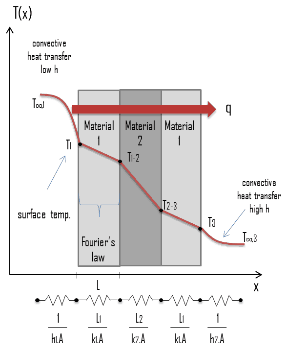
thermal resistance - composite wallsCircuit representations provide a useful tool for both conceptualizing and quantifying heat transfer problems. This analogy can be used also for the thermal resistance of the surface against heat convection. Note that when the convection heat transfer coefficient is very large (h → infinity), the convection resistance becomes zero and the surface temperature approaches the bulk temperature. This situation is approached in practice at surfaces where intensive boiling and condensation occur.

The heat transfer through the composite wall can be calculated from these resistances. The rate of steady heat transfer between two surfaces is equal to the temperature difference divided by the total thermal resistance between those two surfaces.

thermal resistance - equation

The equivalent thermal circuit for the plane wall with convection surface conditions is shown in the figure.

Thermal Contact Resistance – Thermal Contact Conductance

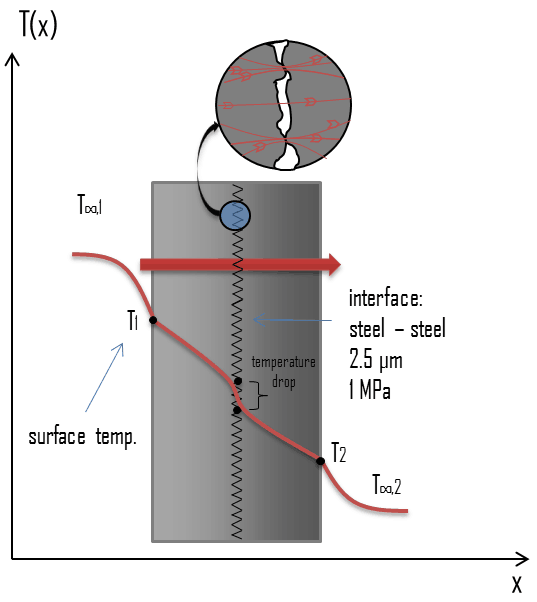
Thermal Contact Resistance - Thermal Contact ConductanceIn thermal engineering, the thermal contact conductance [W/m2.K] or thermal contact resistance [m2.K/W] represents the heat conduction between two solid bodies. When components are bolted or otherwise pressed together, a knowledge of the thermal performance of such joints are also needed. In these composite systems, the temperature drop across the interface between materials may be appreciable. This temperature drop is characterized by the thermal contact conductance coefficient, hc, which is a property indicating the thermal conductivity, or ability to conduct heat, between two bodies in contact. While extensive databases exist on the thermal properties of bulk materials, similar databases for pressed contacts do not.

The inverse of this property is termed thermal contact resistance.

The contact resistance depends on the surface roughness to a great extent. The pressure holding the two surfaces together also influences the contact resistance. Thermal contact resistance is observed to decrease with decreasing surface roughness and increasing interface pressure. This is attributed to the fact that the contact surface between the bodies grows as the contact pressure grows. When two such surfaces are pressed against each other, the peaks will form good material contact but the valleys will form voids filled with air. These voids filled with air act as insulation because of the low thermal conductivity of air. The limited number and size of the contact spots results in an actual contact area which is significantly smaller than the apparent contact area. In case of metallic composite material, which is placed in a vacuum, thermal conduction through the contact spots is the primary mode of heat transfer, and the contact resistance is generally greater than when the composite material is in the presence of air or other fluid. Moreover, thermal contact resistance is significant and may dominate for good heat conductors such as metals but can be neglected for poor heat conductors such as insulators.

For example:

  • The thermal contact conductance for aluminum plates with a surface roughness of 10 μm placed in air with the interface pressure of 1 atm is hc = 3640 W/m2.K
  • The thermal contact conductance for aluminum plates with a surface roughness of 10 μm placed in helium with the interface pressure of 1 atm is hc = 9520 W/m2.K
  • The thermal contact conductance for stainless steel plates with a surface roughness of 2.5 μm placed in air with the interface pressure of 1 MPa is about hc = 3000 W/m2.K

The thermal contact resistance can be minimized by applying a thermally conducting liquid called a thermal grease such as CPU grease on the surfaces before they are pressed against each other. The main role of thermal grease is to eliminate air gaps or spaces (which act as thermal insulator) from the interface area so as to maximize heat transfer. The thermal conductivity of the interstitial material and its pressure are the two properties governing its influence on contact conductance.

Special Reference: Madhusudana, Chakravarti V., Thermal Contact Conductance. Springer International Publishing, 2014. ISBN: 978-3-319-01276-6.

 
References:
Heat Transfer:
  1. Fundamentals of Heat and Mass Transfer, 7th Edition. Theodore L. Bergman, Adrienne S. Lavine, Frank P. Incropera. John Wiley & Sons, Incorporated, 2011. ISBN: 9781118137253.
  2. Heat and Mass Transfer. Yunus A. Cengel. McGraw-Hill Education, 2011. ISBN: 9780071077866.
  3. Fundamentals of Heat and Mass Transfer. C. P. Kothandaraman. New Age International, 2006, ISBN: 9788122417722.
  4. U.S. Department of Energy, Thermodynamics, Heat Transfer and Fluid Flow. DOE Fundamentals Handbook, Volume 2 of 3. May 2016.

Nuclear and Reactor Physics:

  1. J. R. Lamarsh, Introduction to Nuclear Reactor Theory, 2nd ed., Addison-Wesley, Reading, MA (1983).
  2. J. R. Lamarsh, A. J. Baratta, Introduction to Nuclear Engineering, 3d ed., Prentice-Hall, 2001, ISBN: 0-201-82498-1.
  3. W. M. Stacey, Nuclear Reactor Physics, John Wiley & Sons, 2001, ISBN: 0- 471-39127-1.
  4. Glasstone, Sesonske. Nuclear Reactor Engineering: Reactor Systems Engineering, Springer; 4th edition, 1994, ISBN: 978-0412985317
  5. W.S.C. Williams. Nuclear and Particle Physics. Clarendon Press; 1 edition, 1991, ISBN: 978-0198520467
  6. G.R.Keepin. Physics of Nuclear Kinetics. Addison-Wesley Pub. Co; 1st edition, 1965
  7. Robert Reed Burn, Introduction to Nuclear Reactor Operation, 1988.
  8. U.S. Department of Energy, Nuclear Physics and Reactor Theory. DOE Fundamentals Handbook, Volume 1 and 2. January 1993.
  9. Paul Reuss, Neutron Physics. EDP Sciences, 2008. ISBN: 978-2759800414.

Advanced Reactor Physics:

  1. K. O. Ott, W. A. Bezella, Introductory Nuclear Reactor Statics, American Nuclear Society, Revised edition (1989), 1989, ISBN: 0-894-48033-2.
  2. K. O. Ott, R. J. Neuhold, Introductory Nuclear Reactor Dynamics, American Nuclear Society, 1985, ISBN: 0-894-48029-4.
  3. D. L. Hetrick, Dynamics of Nuclear Reactors, American Nuclear Society, 1993, ISBN: 0-894-48453-2.
  4. E. E. Lewis, W. F. Miller, Computational Methods of Neutron Transport, American Nuclear Society, 1993, ISBN: 0-894-48452-4.

See also:

Thermal Conduction

We hope, this article, Thermal Resistance – Thermal Resistivity, helps you. If so, give us a like in the sidebar. Main purpose of this website is to help the public to learn some interesting and important information about thermal engineering.
What is Axial Offset Anomaly – Crud Induced Power Shift – Definition

It was found that axial offset anomaly (AOA) can be caused by crud buildup on high-power fuel assemblies, in which an increased subcooled nucleate boiling can occur. Thermal Engineering

Axial Offset Anomaly

AFD - Axial Flux Difference - Axial Offset ControlAs was written, the axial offset – A/O (or AFD) and the QPTR are direct and continuous measures of the core’s global power distribution. A/O measures global axial power distribution, whereas QPTR measures global azimuthal power distribution. Staying within their limits and proper operation of the control rods should maintain acceptable peaking factors (FQ(z) and FΔH) on a continuous basis. The AFD and QPTR limits ensure that peaking factors (FQ(z) and FΔH) remain below their limiting values by preventing an undetected change in the gross axial and radial power distribution.

In past, some PWR-type nuclear power plants (with LiOH water chemistry) have experienced small radial and especially axial offset anomalies (AOA). That means, some PWRs have experienced a unexpected and gradual shift in the target flux difference (ΔItarget) towards more negative values – shift of power from top half to bottom half.

After extensive research, it was found that axial offset anomaly can be caused by crud buildup on high-power fuel assemblies, in which an increased subcooled nucleate boiling can occur. Therefore this phenomenon is also known as the crud induced power shift (CIPS). Since this subcooled nucleate boiling occurs in the upper part of the assembly, crud accumulation causes an accumulation of boron on the surface of the upper part of the assembly. Lithium borate is absorbed and concentrated in the crud layer, reducing the fission rate in the upper portion of the core. It must be noted, not all reactor cores have experianced the AOA, it is now known that AOA is caused by a combination of high crud level in the coolant, high boiling intensity in the core and is strongly dependent on reactor water chemistry. Note that, some reactor design use LiOH to control pH of the reactor coolant and some use KOH.

In result, during fuel cycle the neutron flux shifts from top half to bottom half and causes an increase in local peaking factors. Crud accumulation may also cause a reduction in available SDM (3-4 pcm/day).  Near the end of cycle, excess burnup in the bottom of the core and reduced boron and lithium concentrations in the reactor coolant system cause the power distribution to shift back toward the upper portion of the core, partially restoring the burnup distribution.

Special Reference: Information Notice No. 97-85: Effects of Crud Buildup and Boron Deposition on Power Distribution and Shutdown Margin, US NRC, 12/1997.

 
AFD vs. A/O
AFD is defined as:

AFD or ΔI = Itop – Ibottom

where Itop and Ibottom are expressed as a fraction of rated thermal power. As an example, assume the core is operating at 100% power. When the Itop = 49% and Ibottom = 51% the resulting ΔI = -2%. When the delta flux target is -5%. The core would then be able to operate with a delta flux of -10% to 0%. The + 5% and -5% flux difference around the target allows for a small amount of movement of the control rods.

For plants operating with so called “constant axial offset control – CAOC”, the AFD limit involves a target band. This target band is, for example, +5% and -5% around the target value. Since the xenon concentration and distribution is flux and time dependent, the longer the core operates outside its target band, the greater the probability of initiating a xenon transient.

Constant Axial Offset Control (CAOC) is a strategy, which is used to control axial power distribution in normal operation. CAOC requires that the AFD must be controlled within a narrow tolerance band around a burnup dependent target to minimize the probability of initiation xenon oscillations during power maneuvers. It also minimizes the variation of axial peaking factors.

Axial offset is defined as:

A/O = (Itop – Ibottom)/(Itop + Ibottom)

where Itop and Ibottom are expressed as a fraction of rated thermal power.


References:
Nuclear and Reactor Physics:
  1. J. R. Lamarsh, Introduction to Nuclear Reactor Theory, 2nd ed., Addison-Wesley, Reading, MA (1983).
  2. J. R. Lamarsh, A. J. Baratta, Introduction to Nuclear Engineering, 3d ed., Prentice-Hall, 2001, ISBN: 0-201-82498-1.
  3. W. M. Stacey, Nuclear Reactor Physics, John Wiley & Sons, 2001, ISBN: 0- 471-39127-1.
  4. Glasstone, Sesonske. Nuclear Reactor Engineering: Reactor Systems Engineering, Springer; 4th edition, 1994, ISBN: 978-0412985317
  5. W.S.C. Williams. Nuclear and Particle Physics. Clarendon Press; 1 edition, 1991, ISBN: 978-0198520467
  6. G.R.Keepin. Physics of Nuclear Kinetics. Addison-Wesley Pub. Co; 1st edition, 1965
  7. Robert Reed Burn, Introduction to Nuclear Reactor Operation, 1988.
  8. U.S. Department of Energy, Nuclear Physics and Reactor Theory. DOE Fundamentals Handbook, Volume 1 and 2. January 1993.

Advanced Reactor Physics:

  1. K. O. Ott, W. A. Bezella, Introductory Nuclear Reactor Statics, American Nuclear Society, Revised edition (1989), 1989, ISBN: 0-894-48033-2.
  2. K. O. Ott, R. J. Neuhold, Introductory Nuclear Reactor Dynamics, American Nuclear Society, 1985, ISBN: 0-894-48029-4.
  3. D. L. Hetrick, Dynamics of Nuclear Reactors, American Nuclear Society, 1993, ISBN: 0-894-48453-2.
  4. E. E. Lewis, W. F. Miller, Computational Methods of Neutron Transport, American Nuclear Society, 1993, ISBN: 0-894-48452-4.

See also:

AFD

We hope, this article, Axial Offset Anomaly – Crud Induced Power Shift, helps you. If so, give us a like in the sidebar. Main purpose of this website is to help the public to learn some interesting and important information about thermal engineering.
What is Fourier’s Law of Thermal Conduction – Definition

Fourier’s law of thermal conduction states that the time rate of heat transfer through a material is proportional to the negative gradient in the temperature and to the area. Thermal Engineering

Fourier’s law of Thermal Conduction

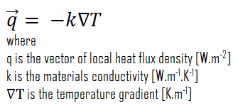
Heat transfer processes can be quantified in terms of appropriate rate equations. The rate equation in this heat transfer mode is based on Fourier’s law of thermal conduction. This law states that the time rate of heat transfer through a material is proportional to the negative gradient in the temperature and to the area, at right angles to that gradient, through which the heat flows. Its differential form is:

Fourier’s law of Thermal Conduction

 
Heat Flux
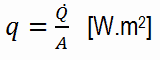
The rate of heat transfer per unit area normal to the direction of heat transfer is called heat flux. Sometimes it is also referred to as heat flux density. In SI its units are watts per square metre (W.m−2). It has both a direction and a magnitude, and so it is a vector quantity. The average heat flux is expressed as:

heat flux density - equation

where A is the heat transfer area. The unit of heat flux in English units is Btu/h·ft2. Note that heat flux may vary with time as well as position on a surface.

In nuclear reactors, limitations of the local heat flux is of the highest importance for reactor safety. Since nuclear fuel consist of fuel rods, the heat flux is there defined in units of W/cm (local linear heat flux) or kW/rod (power per fuel rod).

The proportionality constant obtained in the relation is known as thermal conductivity, k (or λ), of the material. A material that readily transfers energy by conduction is a good thermal conductor and has a high value of k. Fourier’s law is an expression that define the thermal conductivity.

As can be seen, to solve the Fourier’s law we have to involve the temperature difference, the geometry, and the thermal conductivity of the object. This law was first formulated by Joseph Fourier in 1822 who concluded that “the heat flux resulting from thermal conduction is proportional to the magnitude of the temperature gradient and opposite to it in sign”.

Similarly as the Fourier’s law determines the heat flux through a slab, it can also be used to determine the temperature difference, when q is known. This can be used for calculation of the temperature in the centre of fuel pellet as will be shown in following sections.

 
Thermal Conductivity
The heat transfer characteristics of a solid material are measured by a property called the thermal conductivity, k (or λ), measured in W/m.K. It is a measure of a substance’s ability to transfer heat through a material by conduction. Note that Fourier’s law applies for all matter, regardless of its state (solid, liquid, or gas), therefore, it is also defined for liquids and gases.

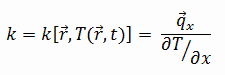
The thermal conductivity of most liquids and solids varies with temperature. For vapors, it also depends upon pressure. In general:

thermal conductivity - definition

Most materials are very nearly homogeneous, therefore we can usually write k = k (T). Similar definitions are associated with thermal conductivities in the y- and z-directions (ky, kz), but for an isotropic material the thermal conductivity is independent of the direction of transfer, kx = ky = kz = k.

From the foregoing equation, it follows that the conduction heat flux increases with increasing thermal conductivity and increases with increasing temperature difference. In general, the thermal conductivity of a solid is larger than that of a liquid, which is larger than that of a gas. This trend is due largely to differences in intermolecular spacing for the two states of matter. In particular, diamond has the highest hardness and thermal conductivity of any bulk material.

See also: Thermal Conductivity

Thermal Conductivity of Uranium Dioxide
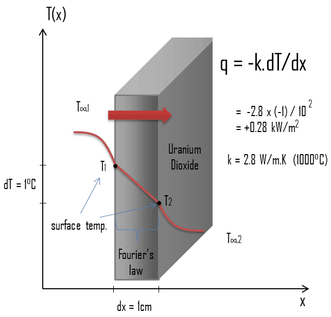
Thermal conduction - thermal conductivity - uranium dioxideMost of PWRs use the uranium fuel, which is in the form of uranium dioxide. Uranium dioxide is a black semiconducting solid with very low thermal conductivity. On the other hand the uranium dioxide has very high melting point and has well known behavior. The UO2 is pressed into pellets, these pellets are then sintered into the solid.

These pellets are then loaded and encapsulated within a fuel rod (or fuel pin), which is made of zirconium alloys due to its very low absorption cross-section (unlike the stainless steel). The surface of the tube, which covers the pellets, is called fuel cladding. Fuel rods are base element of a fuel assembly.

The thermal conductivity of uranium dioxide is very low when compared with metal uranium, uranium nitride, uranium carbide and zirconium cladding material. The thermal conductivity is one of parameters, which determine the fuel centerline temperature. This low thermal conductivity can result in localised overheating in the fuel centerline and therefore this overheating must be avoided.  Overheating of the fuel is prevented by maintaining the steady state peak linear heat rate (LHR) or the Heat Flux Hot Channel Factor – FQ(z) below the level at which fuel centerline melting occurs. Expansion of the fuel pellet upon centerline melting may cause the pellet to stress the cladding to the point of failure.

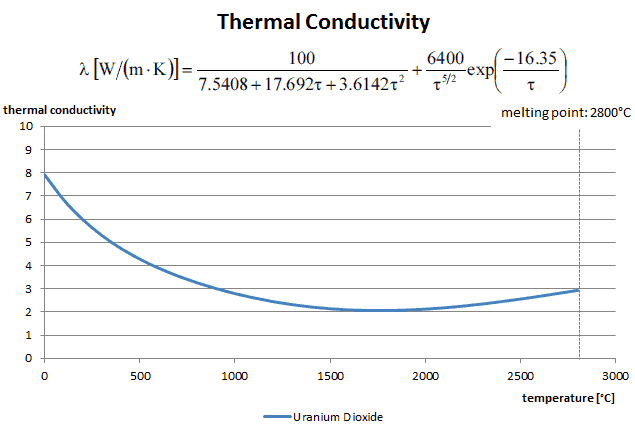
Thermal conductivity of solid UO2 with a density of 95% is estimated by following correlation [Klimenko; Zorin]:

thermal conductivity of uranium - equation

where τ = T/1000. The uncertainty of this correlation is +10% in the range from 298.15 to 2000 K and +20% in the range from 2000 to 3120 K.

Thermal Conductivity - Uranium Dioxide - chart

Special reference: Thermal and Nuclear Power Plants/Handbook ed. by A.V. Klimenko and V.M. Zorin. MEI Press, 2003.

Special reference: Thermophysical Properties of Materials For Nuclear Engineering: A Tutorial and Collection of Data. IAEA-THPH, IAEA, Vienna, 2008. ISBN 978–92–0–106508–7.

Example – Heat flux through a window

Example - Heat Flux - Thermal ConductionHeat loss through windows

A major source of heat loss from a house is through the windows. Calculate the rate of heat flux through a glass window 1.5 m x 1.0 m in area and 3.0 mm thick, if the temperatures at the inner and outer surfaces are 14.0°C and 13.0°C, respectively. Calculate the heat flux through this window.

Solution:

At this point, we know the temperatures at the surfaces of material. These temperatures are given also by conditions inside the house and outside the house. In this case, heat flows by conduction through the glass from the higher inside temperature to the lower outside temperature. We use the Fourier’s law of thermal conduction equation:

Heat loss through window - equation

We assume that the thermal conductivity of a common glass is k = 0.96 W/m.K.

The heat flux will then be:

q = 0.96 [W/m.K] x 1 [K] / 3.0 x 10-3 [m] = 320 W/m2

The total heat loss through this window will be:

qloss = q . A = 320 x 1.5 x 1.0 = 480W

Fourier’s Law and Thermal Resistance

thermal resistance - definition - analogyThermal resistance is the reciprocal of thermal conductance. Just as an electrical resistance is associated with the conduction of electricity, a thermal resistance may be associated with the conduction of heat.

Consider a plane wall of thickness L and average thermal conductivity k. The two surfaces of the wall are maintained at constant temperatures of T1 and T2. For one-dimensional steady heat conduction through the wall, we have T(x). Then Fourier’s law of heat conduction for the wall can be expressed as:

Fourier’s law with thermal resistance

Thermal resistance is a heat property and a measurement of a temperature difference by which an object or material resists a heat flow. The thermal resistance for conduction in a plane wall is defined as:

thermal resistance - definition


References:
Heat Transfer:
  1. Fundamentals of Heat and Mass Transfer, 7th Edition. Theodore L. Bergman, Adrienne S. Lavine, Frank P. Incropera. John Wiley & Sons, Incorporated, 2011. ISBN: 9781118137253.
  2. Heat and Mass Transfer. Yunus A. Cengel. McGraw-Hill Education, 2011. ISBN: 9780071077866.
  3. Fundamentals of Heat and Mass Transfer. C. P. Kothandaraman. New Age International, 2006, ISBN: 9788122417722.
  4. U.S. Department of Energy, Thermodynamics, Heat Transfer and Fluid Flow. DOE Fundamentals Handbook, Volume 2 of 3. May 2016.

Nuclear and Reactor Physics:

  1. J. R. Lamarsh, Introduction to Nuclear Reactor Theory, 2nd ed., Addison-Wesley, Reading, MA (1983).
  2. J. R. Lamarsh, A. J. Baratta, Introduction to Nuclear Engineering, 3d ed., Prentice-Hall, 2001, ISBN: 0-201-82498-1.
  3. W. M. Stacey, Nuclear Reactor Physics, John Wiley & Sons, 2001, ISBN: 0- 471-39127-1.
  4. Glasstone, Sesonske. Nuclear Reactor Engineering: Reactor Systems Engineering, Springer; 4th edition, 1994, ISBN: 978-0412985317
  5. W.S.C. Williams. Nuclear and Particle Physics. Clarendon Press; 1 edition, 1991, ISBN: 978-0198520467
  6. G.R.Keepin. Physics of Nuclear Kinetics. Addison-Wesley Pub. Co; 1st edition, 1965
  7. Robert Reed Burn, Introduction to Nuclear Reactor Operation, 1988.
  8. U.S. Department of Energy, Nuclear Physics and Reactor Theory. DOE Fundamentals Handbook, Volume 1 and 2. January 1993.
  9. Paul Reuss, Neutron Physics. EDP Sciences, 2008. ISBN: 978-2759800414.

Advanced Reactor Physics:

  1. K. O. Ott, W. A. Bezella, Introductory Nuclear Reactor Statics, American Nuclear Society, Revised edition (1989), 1989, ISBN: 0-894-48033-2.
  2. K. O. Ott, R. J. Neuhold, Introductory Nuclear Reactor Dynamics, American Nuclear Society, 1985, ISBN: 0-894-48029-4.
  3. D. L. Hetrick, Dynamics of Nuclear Reactors, American Nuclear Society, 1993, ISBN: 0-894-48453-2.
  4. E. E. Lewis, W. F. Miller, Computational Methods of Neutron Transport, American Nuclear Society, 1993, ISBN: 0-894-48452-4.

See also:

Thermal Conduction

We hope, this article, Fourier’s Law of Thermal Conduction, helps you. If so, give us a like in the sidebar. Main purpose of this website is to help the public to learn some interesting and important information about thermal engineering.
What is Thermal Resistance – Specific Thermal Resistance – Definition

Definition of Thermal Resistance. Specific thermal resistance or specific thermal resistivity, Rλ, which has units of [(K·m)/W]. Specific thermal is a material constant. Thermal Engineering

Definition of Thermal Resistance

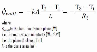
Thermal resistance is a heat property and a measurement of a temperature difference by which an object or material resists a heat flow. The thermal resistance for conduction in a plane wall is defined as:

thermal resistance - definition

Since the concept of thermal resistance can be used in a variety of engineering branches, we define:

  • Absolute thermal resistance, Rt, which has units of [K/W]. Absolute thermal resistance is a property of a particular component, which has defined geometry (thickness – L, area – A and shape). For example, a characteristic of a defined heat exchanger. Only a temperature difference is needed to solve for heat transferred.
  • Specific thermal resistance or specific thermal resistivity, Rλ, which has units of [(K·m)/W]. Specific thermal is a material constant. Material thickness and a temperature difference is required to solve for heat transferred.
  • R-value. R-value (thermal insulance factor) is a measure of thermal resistance. The higher the R-value, the greater the insulating effectiveness. Thermal insulance has the units [(m2.K)/W] in SI units or [(ft2·°F·hr)/Btu] in imperial units. It is the thermal resistance of unit area of a material. The R-value depends on the type of insulation, its thickness, and its density. An area and a temperature difference is required to solve for heat transferred.
 
References:
Heat Transfer:
  1. Fundamentals of Heat and Mass Transfer, 7th Edition. Theodore L. Bergman, Adrienne S. Lavine, Frank P. Incropera. John Wiley & Sons, Incorporated, 2011. ISBN: 9781118137253.
  2. Heat and Mass Transfer. Yunus A. Cengel. McGraw-Hill Education, 2011. ISBN: 9780071077866.
  3. Fundamentals of Heat and Mass Transfer. C. P. Kothandaraman. New Age International, 2006, ISBN: 9788122417722.
  4. U.S. Department of Energy, Thermodynamics, Heat Transfer and Fluid Flow. DOE Fundamentals Handbook, Volume 2 of 3. May 2016.

Nuclear and Reactor Physics:

  1. J. R. Lamarsh, Introduction to Nuclear Reactor Theory, 2nd ed., Addison-Wesley, Reading, MA (1983).
  2. J. R. Lamarsh, A. J. Baratta, Introduction to Nuclear Engineering, 3d ed., Prentice-Hall, 2001, ISBN: 0-201-82498-1.
  3. W. M. Stacey, Nuclear Reactor Physics, John Wiley & Sons, 2001, ISBN: 0- 471-39127-1.
  4. Glasstone, Sesonske. Nuclear Reactor Engineering: Reactor Systems Engineering, Springer; 4th edition, 1994, ISBN: 978-0412985317
  5. W.S.C. Williams. Nuclear and Particle Physics. Clarendon Press; 1 edition, 1991, ISBN: 978-0198520467
  6. G.R.Keepin. Physics of Nuclear Kinetics. Addison-Wesley Pub. Co; 1st edition, 1965
  7. Robert Reed Burn, Introduction to Nuclear Reactor Operation, 1988.
  8. U.S. Department of Energy, Nuclear Physics and Reactor Theory. DOE Fundamentals Handbook, Volume 1 and 2. January 1993.
  9. Paul Reuss, Neutron Physics. EDP Sciences, 2008. ISBN: 978-2759800414.

Advanced Reactor Physics:

  1. K. O. Ott, W. A. Bezella, Introductory Nuclear Reactor Statics, American Nuclear Society, Revised edition (1989), 1989, ISBN: 0-894-48033-2.
  2. K. O. Ott, R. J. Neuhold, Introductory Nuclear Reactor Dynamics, American Nuclear Society, 1985, ISBN: 0-894-48029-4.
  3. D. L. Hetrick, Dynamics of Nuclear Reactors, American Nuclear Society, 1993, ISBN: 0-894-48453-2.
  4. E. E. Lewis, W. F. Miller, Computational Methods of Neutron Transport, American Nuclear Society, 1993, ISBN: 0-894-48452-4.

See also:

Thermal Resistivity

We hope, this article, Thermal Resistance – Specific Thermal Resistance, helps you. If so, give us a like in the sidebar. Main purpose of this website is to help the public to learn some interesting and important information about thermal engineering.
What is R-value – Thermal Insulance Factor – Definition

R-value, the thermal insulance factor, is a measure of thermal resistance. The higher the R-value, the greater the insulating effectiveness.Thermal insulance has the units [(m2.K)/W]

R-value – Thermal Insulance Factor

Thermal resistance is a heat property and a measurement of a temperature difference by which an object or material resists a heat flow. The thermal resistance for conduction in a plane wall is defined as:

thermal resistance - definition

Since the concept of thermal resistance can be used in a variety of engineering branches, we define:

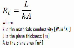
  • Absolute thermal resistance, Rt, which has units of [K/W]. Absolute thermal resistance is a property of a particular component, which has defined geometry (thickness – L, area – A and shape). For example, a characteristic of a defined heat exchanger. Only a temperature difference is needed to solve for heat transferred.
  • Specific thermal resistance or specific thermal resistivity, Rλ, which has units of [(K·m)/W]. Specific thermal is a material constant. Material thickness and a temperature difference is required to solve for heat transferred.
  • R-value. R-value (thermal insulance factor) is a measure of thermal resistance. The higher the R-value, the greater the insulating effectiveness. Thermal insulance has the units [(m2.K)/W] in SI units or [(ft2·°F·hr)/Btu] in imperial units. It is the thermal resistance of unit area of a material. The R-value depends on the type of insulation, its thickness, and its density. An area and a temperature difference is required to solve for heat transferred.

R-value

The construction industry makes use of units such as the R-value (resistance), which is expressed as the thickness of the material normalized to the thermal conductivity, and under uniform conditions it is the ratio of the temperature difference across an insulator and the heat flux density through it: R(x) = ∆T/q. The higher the R-value, the more a material prevents heat transfer. As can be seen, the resistance is dependent on the thickness of the product.

Thermal Resistance – Thermal Resistivity

thermal resistance - definition - analogyIn engineering, another very important concept is often used. Since there is an analogy between the diffusion of heat and electrical charge, engineers often use the thermal resistance (i.e. thermal resistance against heat conduction) to calculate heat transfer through materials. Thermal resistance is the reciprocal of thermal conductance. Just as an electrical resistance is associated with the conduction of electricity, a thermal resistance may be associated with the conduction of heat.

Consider a plane wall of thickness L and average thermal conductivity k. The two surfaces of the wall are maintained at constant temperatures of T1 and T2. For one-dimensional steady heat conduction through the wall, we have T(x). Then Fourier’s law of heat conduction for the wall can be expressed as:

Fourier’s law with thermal resistance

 
References:
Heat Transfer:
  1. Fundamentals of Heat and Mass Transfer, 7th Edition. Theodore L. Bergman, Adrienne S. Lavine, Frank P. Incropera. John Wiley & Sons, Incorporated, 2011. ISBN: 9781118137253.
  2. Heat and Mass Transfer. Yunus A. Cengel. McGraw-Hill Education, 2011. ISBN: 9780071077866.
  3. Fundamentals of Heat and Mass Transfer. C. P. Kothandaraman. New Age International, 2006, ISBN: 9788122417722.
  4. U.S. Department of Energy, Thermodynamics, Heat Transfer and Fluid Flow. DOE Fundamentals Handbook, Volume 2 of 3. May 2016.

Nuclear and Reactor Physics:

  1. J. R. Lamarsh, Introduction to Nuclear Reactor Theory, 2nd ed., Addison-Wesley, Reading, MA (1983).
  2. J. R. Lamarsh, A. J. Baratta, Introduction to Nuclear Engineering, 3d ed., Prentice-Hall, 2001, ISBN: 0-201-82498-1.
  3. W. M. Stacey, Nuclear Reactor Physics, John Wiley & Sons, 2001, ISBN: 0- 471-39127-1.
  4. Glasstone, Sesonske. Nuclear Reactor Engineering: Reactor Systems Engineering, Springer; 4th edition, 1994, ISBN: 978-0412985317
  5. W.S.C. Williams. Nuclear and Particle Physics. Clarendon Press; 1 edition, 1991, ISBN: 978-0198520467
  6. G.R.Keepin. Physics of Nuclear Kinetics. Addison-Wesley Pub. Co; 1st edition, 1965
  7. Robert Reed Burn, Introduction to Nuclear Reactor Operation, 1988.
  8. U.S. Department of Energy, Nuclear Physics and Reactor Theory. DOE Fundamentals Handbook, Volume 1 and 2. January 1993.
  9. Paul Reuss, Neutron Physics. EDP Sciences, 2008. ISBN: 978-2759800414.

Advanced Reactor Physics:

  1. K. O. Ott, W. A. Bezella, Introductory Nuclear Reactor Statics, American Nuclear Society, Revised edition (1989), 1989, ISBN: 0-894-48033-2.
  2. K. O. Ott, R. J. Neuhold, Introductory Nuclear Reactor Dynamics, American Nuclear Society, 1985, ISBN: 0-894-48029-4.
  3. D. L. Hetrick, Dynamics of Nuclear Reactors, American Nuclear Society, 1993, ISBN: 0-894-48453-2.
  4. E. E. Lewis, W. F. Miller, Computational Methods of Neutron Transport, American Nuclear Society, 1993, ISBN: 0-894-48452-4.

See also:

Thermal Resistivity

We hope, this article, R-value – Thermal Insulance Factor, helps you. If so, give us a like in the sidebar. Main purpose of this website is to help the public to learn some interesting and important information about thermal engineering.

What is Thermal Resistance – Analogy to Electric Resistance – Definition

Thermal Resistance – Analogy to Electric Resistance. The rate of heat transfer through a layer corresponds to the electric current, the thermal resistance corresponds to electrical resistance. Thermal Engineering

Thermal Resistance – Thermal Resistivity

thermal resistance - definition - analogyIn engineering, another very important concept is often used. Since there is an analogy between the diffusion of heat and electrical charge, engineers often use the thermal resistance (i.e. thermal resistance against heat conduction) to calculate heat transfer through materials. Thermal resistance is the reciprocal of thermal conductance. Just as an electrical resistance is associated with the conduction of electricity, a thermal resistance may be associated with the conduction of heat.

Consider a plane wall of thickness L and average thermal conductivity k. The two surfaces of the wall are maintained at constant temperatures of T1 and T2. For one-dimensional steady heat conduction through the wall, we have T(x). Then Fourier’s law of heat conduction for the wall can be expressed as:

Fourier’s law with thermal resistance

Definition of Thermal Resistance

Thermal resistance is a heat property and a measurement of a temperature difference by which an object or material resists a heat flow. The thermal resistance for conduction in a plane wall is defined as:

thermal resistance - definition

Since the concept of thermal resistance can be used in a variety of engineering branches, we define:

  • Absolute thermal resistance, Rt, which has units of [K/W]. Absolute thermal resistance is a property of a particular component, which has defined geometry (thickness – L, area – A and shape). For example, a characteristic of a defined heat exchanger. Only a temperature difference is needed to solve for heat transferred.
  • Specific thermal resistance or specific thermal resistivity, Rλ, which has units of [(K·m)/W]. Specific thermal is a material constant. Material thickness and a temperature difference is required to solve for heat transferred.
  • R-value. R-value (thermal insulance factor) is a measure of thermal resistance. The higher the R-value, the greater the insulating effectiveness. Thermal insulance has the units [(m2.K)/W] in SI units or [(ft2·°F·hr)/Btu] in imperial units. It is the thermal resistance of unit area of a material. The R-value depends on the type of insulation, its thickness, and its density. An area and a temperature difference is required to solve for heat transferred.

Analogy to Electric Resistance

The equation above for heat flow is analogous to the relation for electric current flow I, expressed as:

analogy to electric resistance

where Re = L/σeA is the electric resistance and V1 – V2 is the voltage difference across the resistance (σe is the electrical conductivity). The analogy between both equations is obvious. The rate of heat transfer through a layer corresponds to the electric current, the thermal resistance corresponds to electrical resistance, and the temperature difference corresponds to voltage difference across the layer. The temperature difference is the potential or driving function for the heat flow, resulting in the Fourier equation being written in a form similar to Ohm’s Law of Electrical Circuit Theory.

thermal resistance - composite wallsCircuit representations provide a useful tool for both conceptualizing and quantifying heat transfer problems. This analogy can be used also for the thermal resistance of the surface against heat convection. Note that when the convection heat transfer coefficient is very large (h → infinity), the convection resistance becomes zero and the surface temperature approaches the bulk temperature. This situation is approached in practice at surfaces where intensive boiling and condensation occur.

The heat transfer through the composite wall can be calculated from these resistances. The rate of steady heat transfer between two surfaces is equal to the temperature difference divided by the total thermal resistance between those two surfaces.

thermal resistance - equation

The equivalent thermal circuit for the plane wall with convection surface conditions is shown in the figure.

See also: Wiedemann–Franz Law

 
References:
Heat Transfer:
  1. Fundamentals of Heat and Mass Transfer, 7th Edition. Theodore L. Bergman, Adrienne S. Lavine, Frank P. Incropera. John Wiley & Sons, Incorporated, 2011. ISBN: 9781118137253.
  2. Heat and Mass Transfer. Yunus A. Cengel. McGraw-Hill Education, 2011. ISBN: 9780071077866.
  3. Fundamentals of Heat and Mass Transfer. C. P. Kothandaraman. New Age International, 2006, ISBN: 9788122417722.
  4. U.S. Department of Energy, Thermodynamics, Heat Transfer and Fluid Flow. DOE Fundamentals Handbook, Volume 2 of 3. May 2016.

Nuclear and Reactor Physics:

  1. J. R. Lamarsh, Introduction to Nuclear Reactor Theory, 2nd ed., Addison-Wesley, Reading, MA (1983).
  2. J. R. Lamarsh, A. J. Baratta, Introduction to Nuclear Engineering, 3d ed., Prentice-Hall, 2001, ISBN: 0-201-82498-1.
  3. W. M. Stacey, Nuclear Reactor Physics, John Wiley & Sons, 2001, ISBN: 0- 471-39127-1.
  4. Glasstone, Sesonske. Nuclear Reactor Engineering: Reactor Systems Engineering, Springer; 4th edition, 1994, ISBN: 978-0412985317
  5. W.S.C. Williams. Nuclear and Particle Physics. Clarendon Press; 1 edition, 1991, ISBN: 978-0198520467
  6. G.R.Keepin. Physics of Nuclear Kinetics. Addison-Wesley Pub. Co; 1st edition, 1965
  7. Robert Reed Burn, Introduction to Nuclear Reactor Operation, 1988.
  8. U.S. Department of Energy, Nuclear Physics and Reactor Theory. DOE Fundamentals Handbook, Volume 1 and 2. January 1993.
  9. Paul Reuss, Neutron Physics. EDP Sciences, 2008. ISBN: 978-2759800414.

Advanced Reactor Physics:

  1. K. O. Ott, W. A. Bezella, Introductory Nuclear Reactor Statics, American Nuclear Society, Revised edition (1989), 1989, ISBN: 0-894-48033-2.
  2. K. O. Ott, R. J. Neuhold, Introductory Nuclear Reactor Dynamics, American Nuclear Society, 1985, ISBN: 0-894-48029-4.
  3. D. L. Hetrick, Dynamics of Nuclear Reactors, American Nuclear Society, 1993, ISBN: 0-894-48453-2.
  4. E. E. Lewis, W. F. Miller, Computational Methods of Neutron Transport, American Nuclear Society, 1993, ISBN: 0-894-48452-4.

See also:

Thermal Resistivity

We hope, this article, Thermal Resistance – Analogy to Electric Resistance, helps you. If so, give us a like in the sidebar. Main purpose of this website is to help the public to learn some interesting and important information about thermal engineering.

What is Thermal Contact Resistance – Thermal Contact Conductance – Definition

In thermal engineering, the thermal contact conductance [W/m2.K] or thermal contact resistance [m2.K/W] represents the heat conduction between two solid bodies. Thermal Engineering

Thermal Contact Resistance – Thermal Contact Conductance

Thermal Contact Resistance - Thermal Contact ConductanceIn thermal engineering, the thermal contact conductance [W/m2.K] or thermal contact resistance [m2.K/W] represents the heat conduction between two solid bodies. When components are bolted or otherwise pressed together, a knowledge of the thermal performance of such joints are also needed. In these composite systems, the temperature drop across the interface between materials may be appreciable. This temperature drop is characterized by the thermal contact conductance coefficient, hc, which is a property indicating the thermal conductivity, or ability to conduct heat, between two bodies in contact. While extensive databases exist on the thermal properties of bulk materials, similar databases for pressed contacts do not.

The inverse of this property is termed thermal contact resistance.

The contact resistance depends on the surface roughness to a great extent. The pressure holding the two surfaces together also influences the contact resistance. Thermal contact resistance is observed to decrease with decreasing surface roughness and increasing interface pressure. This is attributed to the fact that the contact surface between the bodies grows as the contact pressure grows. When two such surfaces are pressed against each other, the peaks will form good material contact but the valleys will form voids filled with air. These voids filled with air act as insulation because of the low thermal conductivity of air. The limited number and size of the contact spots results in an actual contact area which is significantly smaller than the apparent contact area. In case of metallic composite material, which is placed in a vacuum, thermal conduction through the contact spots is the primary mode of heat transfer, and the contact resistance is generally greater than when the composite material is in the presence of air or other fluid. Moreover, thermal contact resistance is significant and may dominate for good heat conductors such as metals but can be neglected for poor heat conductors such as insulators.

For example:

  • The thermal contact conductance for aluminum plates with a surface roughness of 10 μm placed in air with the interface pressure of 1 atm is hc = 3640 W/m2.K
  • The thermal contact conductance for aluminum plates with a surface roughness of 10 μm placed in helium with the interface pressure of 1 atm is hc = 9520 W/m2.K
  • The thermal contact conductance for stainless steel plates with a surface roughness of 2.5 μm placed in air with the interface pressure of 1 MPa is about hc = 3000 W/m2.K

The thermal contact resistance can be minimized by applying a thermally conducting liquid called a thermal grease such as CPU grease on the surfaces before they are pressed against each other. The main role of thermal grease is to eliminate air gaps or spaces (which act as thermal insulator) from the interface area so as to maximize heat transfer. The thermal conductivity of the interstitial material and its pressure are the two properties governing its influence on contact conductance.

Special Reference: Madhusudana, Chakravarti V., Thermal Contact Conductance. Springer International Publishing, 2014. ISBN: 978-3-319-01276-6.

 
References:
Heat Transfer:
  1. Fundamentals of Heat and Mass Transfer, 7th Edition. Theodore L. Bergman, Adrienne S. Lavine, Frank P. Incropera. John Wiley & Sons, Incorporated, 2011. ISBN: 9781118137253.
  2. Heat and Mass Transfer. Yunus A. Cengel. McGraw-Hill Education, 2011. ISBN: 9780071077866.
  3. Fundamentals of Heat and Mass Transfer. C. P. Kothandaraman. New Age International, 2006, ISBN: 9788122417722.
  4. U.S. Department of Energy, Thermodynamics, Heat Transfer and Fluid Flow. DOE Fundamentals Handbook, Volume 2 of 3. May 2016.

Nuclear and Reactor Physics:

  1. J. R. Lamarsh, Introduction to Nuclear Reactor Theory, 2nd ed., Addison-Wesley, Reading, MA (1983).
  2. J. R. Lamarsh, A. J. Baratta, Introduction to Nuclear Engineering, 3d ed., Prentice-Hall, 2001, ISBN: 0-201-82498-1.
  3. W. M. Stacey, Nuclear Reactor Physics, John Wiley & Sons, 2001, ISBN: 0- 471-39127-1.
  4. Glasstone, Sesonske. Nuclear Reactor Engineering: Reactor Systems Engineering, Springer; 4th edition, 1994, ISBN: 978-0412985317
  5. W.S.C. Williams. Nuclear and Particle Physics. Clarendon Press; 1 edition, 1991, ISBN: 978-0198520467
  6. G.R.Keepin. Physics of Nuclear Kinetics. Addison-Wesley Pub. Co; 1st edition, 1965
  7. Robert Reed Burn, Introduction to Nuclear Reactor Operation, 1988.
  8. U.S. Department of Energy, Nuclear Physics and Reactor Theory. DOE Fundamentals Handbook, Volume 1 and 2. January 1993.
  9. Paul Reuss, Neutron Physics. EDP Sciences, 2008. ISBN: 978-2759800414.

Advanced Reactor Physics:

  1. K. O. Ott, W. A. Bezella, Introductory Nuclear Reactor Statics, American Nuclear Society, Revised edition (1989), 1989, ISBN: 0-894-48033-2.
  2. K. O. Ott, R. J. Neuhold, Introductory Nuclear Reactor Dynamics, American Nuclear Society, 1985, ISBN: 0-894-48029-4.
  3. D. L. Hetrick, Dynamics of Nuclear Reactors, American Nuclear Society, 1993, ISBN: 0-894-48453-2.
  4. E. E. Lewis, W. F. Miller, Computational Methods of Neutron Transport, American Nuclear Society, 1993, ISBN: 0-894-48452-4.

See also:

Thermal Resistivity

We hope, this article, Thermal Contact Resistance – Thermal Contact Conductance, helps you. If so, give us a like in the sidebar. Main purpose of this website is to help the public to learn some interesting and important information about thermal engineering.

What is Thermal Grease – CPU Grease – Definition

The thermal contact resistance can be minimized by applying a thermally conducting liquid called a thermal grease such as CPU grease on the surfaces. Thermal Engineering

Thermal Grease – CPU Grease

Thermal Contact Resistance - Thermal Contact Conductance

The thermal contact resistance can be minimized by applying a thermally conducting liquid called a thermal grease such as CPU grease on the surfaces before they are pressed against each other. The main role of thermal grease is to eliminate air gaps or spaces (which act as thermal insulator) from the interface area so as to maximize heat transfer. The thermal conductivity of the interstitial material and its pressure are the two properties governing its influence on contact conductance.

In thermal engineering, the thermal contact conductance [W/m2.K] or thermal contact resistance [m2.K/W] represents the heat conduction between two solid bodies. When components are bolted or otherwise pressed together, a knowledge of the thermal performance of such joints are also needed. In these composite systems, the temperature drop across the interface between materials may be appreciable. This temperature drop is characterized by the thermal contact conductance coefficient, hc, which is a property indicating the thermal conductivity, or ability to conduct heat, between two bodies in contact. While extensive databases exist on the thermal properties of bulk materials, similar databases for pressed contacts do not.

The inverse of this property is termed thermal contact resistance.

The contact resistance depends on the surface roughness to a great extent. The pressure holding the two surfaces together also influences the contact resistance. Thermal contact resistance is observed to decrease with decreasing surface roughness and increasing interface pressure. This is attributed to the fact that the contact surface between the bodies grows as the contact pressure grows. When two such surfaces are pressed against each other, the peaks will form good material contact but the valleys will form voids filled with air. These voids filled with air act as insulation because of the low thermal conductivity of air. The limited number and size of the contact spots results in an actual contact area which is significantly smaller than the apparent contact area. In case of metallic composite material, which is placed in a vacuum, thermal conduction through the contact spots is the primary mode of heat transfer, and the contact resistance is generally greater than when the composite material is in the presence of air or other fluid. Moreover, thermal contact resistance is significant and may dominate for good heat conductors such as metals but can be neglected for poor heat conductors such as insulators.

For example:

  • The thermal contact conductance for aluminum plates with a surface roughness of 10 μm placed in air with the interface pressure of 1 atm is hc = 3640 W/m2.K
  • The thermal contact conductance for aluminum plates with a surface roughness of 10 μm placed in helium with the interface pressure of 1 atm is hc = 9520 W/m2.K
  • The thermal contact conductance for stainless steel plates with a surface roughness of 2.5 μm placed in air with the interface pressure of 1 MPa is about hc = 3000 W/m2.K

Special Reference: Madhusudana, Chakravarti V., Thermal Contact Conductance. Springer International Publishing, 2014. ISBN: 978-3-319-01276-6.

 
References:
Heat Transfer:
  1. Fundamentals of Heat and Mass Transfer, 7th Edition. Theodore L. Bergman, Adrienne S. Lavine, Frank P. Incropera. John Wiley & Sons, Incorporated, 2011. ISBN: 9781118137253.
  2. Heat and Mass Transfer. Yunus A. Cengel. McGraw-Hill Education, 2011. ISBN: 9780071077866.
  3. Fundamentals of Heat and Mass Transfer. C. P. Kothandaraman. New Age International, 2006, ISBN: 9788122417722.
  4. U.S. Department of Energy, Thermodynamics, Heat Transfer and Fluid Flow. DOE Fundamentals Handbook, Volume 2 of 3. May 2016.

Nuclear and Reactor Physics:

  1. J. R. Lamarsh, Introduction to Nuclear Reactor Theory, 2nd ed., Addison-Wesley, Reading, MA (1983).
  2. J. R. Lamarsh, A. J. Baratta, Introduction to Nuclear Engineering, 3d ed., Prentice-Hall, 2001, ISBN: 0-201-82498-1.
  3. W. M. Stacey, Nuclear Reactor Physics, John Wiley & Sons, 2001, ISBN: 0- 471-39127-1.
  4. Glasstone, Sesonske. Nuclear Reactor Engineering: Reactor Systems Engineering, Springer; 4th edition, 1994, ISBN: 978-0412985317
  5. W.S.C. Williams. Nuclear and Particle Physics. Clarendon Press; 1 edition, 1991, ISBN: 978-0198520467
  6. G.R.Keepin. Physics of Nuclear Kinetics. Addison-Wesley Pub. Co; 1st edition, 1965
  7. Robert Reed Burn, Introduction to Nuclear Reactor Operation, 1988.
  8. U.S. Department of Energy, Nuclear Physics and Reactor Theory. DOE Fundamentals Handbook, Volume 1 and 2. January 1993.
  9. Paul Reuss, Neutron Physics. EDP Sciences, 2008. ISBN: 978-2759800414.

Advanced Reactor Physics:

  1. K. O. Ott, W. A. Bezella, Introductory Nuclear Reactor Statics, American Nuclear Society, Revised edition (1989), 1989, ISBN: 0-894-48033-2.
  2. K. O. Ott, R. J. Neuhold, Introductory Nuclear Reactor Dynamics, American Nuclear Society, 1985, ISBN: 0-894-48029-4.
  3. D. L. Hetrick, Dynamics of Nuclear Reactors, American Nuclear Society, 1993, ISBN: 0-894-48453-2.
  4. E. E. Lewis, W. F. Miller, Computational Methods of Neutron Transport, American Nuclear Society, 1993, ISBN: 0-894-48452-4.

See also:

Thermal Resistivity

We hope, this article, Thermal Grease – CPU Grease, helps you. If so, give us a like in the sidebar. Main purpose of this website is to help the public to learn some interesting and important information about thermal engineering.