Facebook Instagram Youtube Twitter

What is Heat Transfer – Definition

Heat transfer is an engineering discipline that concerns the generation, use, conversion, and exchange of heat (thermal energy) between physical systems. Thermal Engineering

Heat Transfer

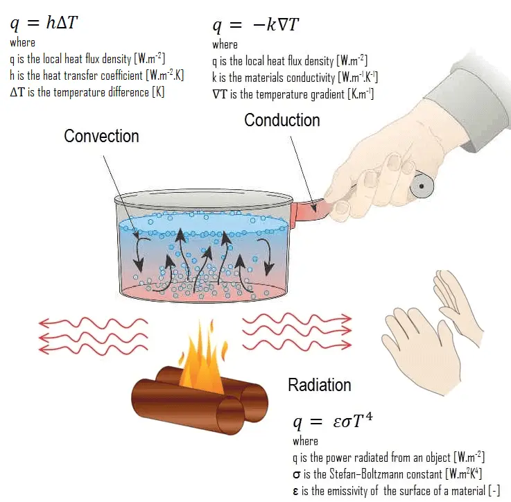
Heat Transfer - mechanismsHeat transfer is an engineering discipline that concerns the generation, use, conversion, and exchange of heat (thermal energy) between physical systems.  In power engineering it determines key parameters and materials of heat exchangers. Heat transfer is usually classified into various mechanisms, such as:

  • Heat Conduction. Heat conduction, also called diffusion, occurs within a body or between two bodies in contact. It is the direct microscopic exchange of kinetic energy of particles through the boundary between two systems. When an object is at a different temperature from another body or its surroundings
  • Heat Convection. Heat convection depends on motion of mass from one region of space to another. Heat convection occurs when bulk flow of a fluid (gas or liquid) carries heat along with the flow of matter in the fluid.
  • Thermal Radiation. Radiation is heat transfer by electromagnetic radiation, such as sunshine, with no need for matter to be present in the space between bodies.
 
Thermodynamics and Heat Transfer
Thermodynamics is the science that deals with energy production, storage, transfer and conversion. It studies the effects of work, heat and energy on a system as a system undergoes a process from one equilibrium state to another, and makes no reference to how long the process will take. But in engineering, we are often interested in the rate of heat transfer, which is the topic of the science of heat transfer. We can recall from thermodynamics that energy exists in various forms.

Heat transfer is primarily interested in heat, which is the form of energy that can be transferred from one system to another as a result of temperature difference. The engineering thermodynamics might better be named thermostatics, because it describes primarily the equilibrium states on either side of irreversible processes.

In engineering, the term convective heat transfer is used to describe the combined effects of conduction and fluid flow.  At this point, we have to add a new mechanism, which is known as advection (the transport of a substance by bulk motion). From the thermodynamic point of view, heat flows into a fluid by diffusion to increase its energy, the fluid then transfers (advects) this increased internal energy (not heat) from one location to another, and this is then followed by a second thermal interaction which transfers heat to a second body or system, again by diffusion.

Heat Transfer in Nuclear Engineering – Application

Heat transfer is commonly encountered in engineering systems and other aspects of life, and one does not need to go very far to see some application areas of heat transfer.
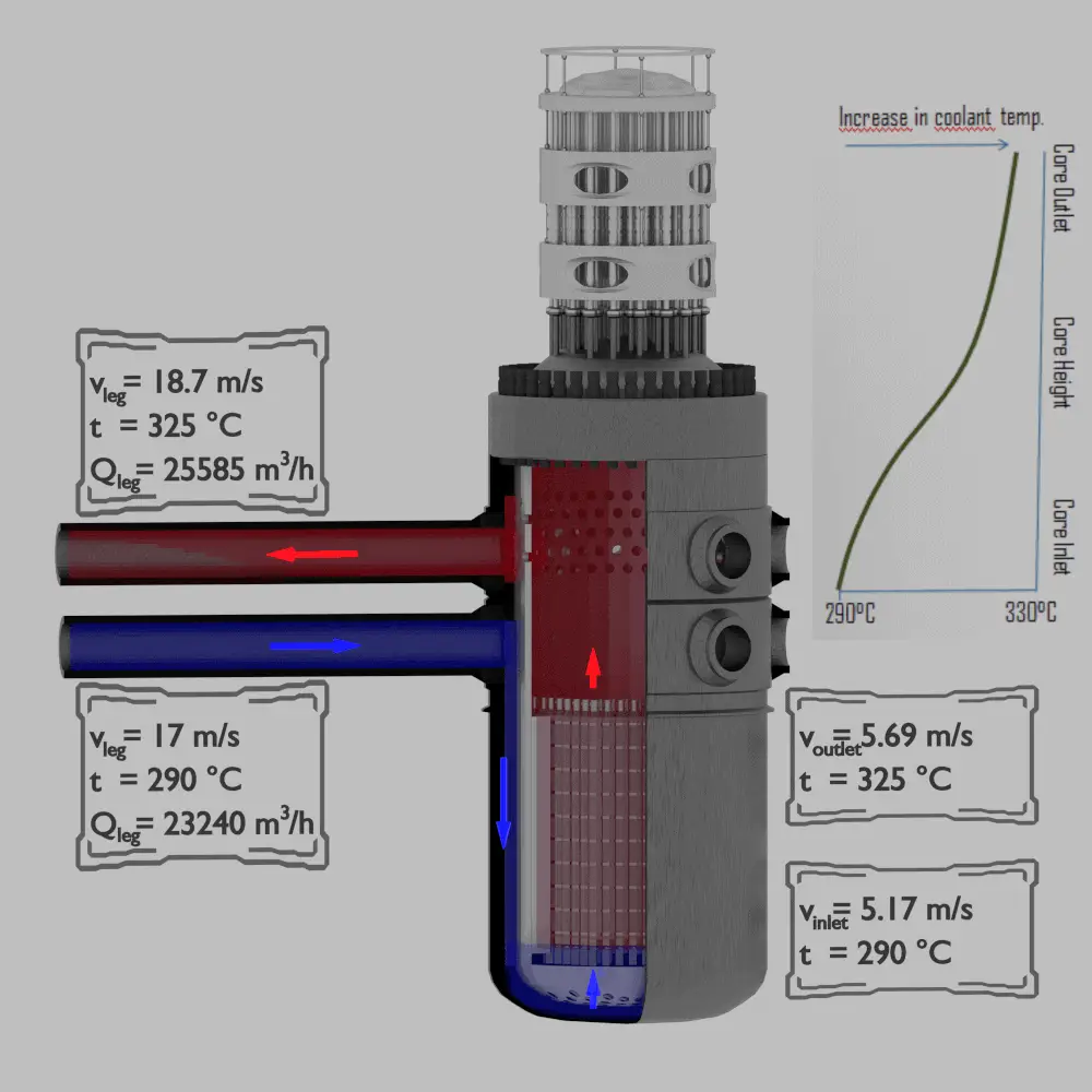
Continuity Equation - Flow Rates through Reactor
Example of flow rates in a reactor. It is an illustrative example, data do not represent any reactor design.

Detailed knowledge of heat transfer mechanisms is also essential for reactor engineers as well as all other engineers. A nuclear power plant (nuclear power station) looks like a standard thermal power station with one exception. The heat source in the nuclear power plant is a nuclear reactor. As is typical in all conventional thermal power stations the heat is used to generate steam which drives a steam turbine connected to a generator which produces electricity. But in nuclear power plants reactors produce enormous amount of heat (energy) in a small volume. The density of the energy generation is very large and this puts demands on its heat transfer system (reactor coolant system). Therefore we have to start by the reactor heat generation and removal from the reactor.

For a reactor to operate in a steady state, all of the heat released in the system must be removed as fast as it is produced. This is accomplished by passing a liquid or gaseous coolant through the core and through other regions where heat is generated. The heat transfer must be equal to or greater than the heat generation rate or overheating and possible damage to the fuel may occur. The nature and operation of this coolant system is one of the most important considerations in the design of a nuclear reactor.

It should be noted that from a strictly nuclear standpoint, there is theoretically no upper limit to the reactor thermal power, which can be attained by any critical reactor having sufficient excess of reactivity to overcome its negative temperature feedbacks. In each nuclear reactor, there is a direct proportionality between the neutron flux and the reactor thermal power. The term thermal power is usually used, because it means the rate at which heat is produced in the reactor core as the result of fissions in the fuel. Moreover, for a short period, a critical reactor does not need to have high excess of reactivity as in case of rapid reactivity excursions.

In short, almost any reactor is able to exceed the ability of heat removal of its coolant system. Beyond this point, the fuel would heat up and can reach very high temperatures. This situation must be avoided by reactor operator and by reactor safety systems. It is essential, that the heat generation – heat removal rate balance must be maintained to prevent these temperatures that might result in the failure of fuel or other structural materials. In reactor engineering, the thermal-hydraulics of nuclear reactors describe the effort involving the coupling of heat transfer and fluid dynamics to accomplish the desired heat removal rate from the core under both normal operation and accident conditions.

 
Thermal Efficiency of Nuclear Power Plants
The thermal efficiency of the conversion of thermal energy to work is primarily determined by the difference between the hot and cold temperature reservoirs. Thermal efficiency is improved if the heat input from the steam to the steam turbine is at as high a temperature as possible and the heat rejection in the condenser is at as low a temperature as possible. The high temperature in a light water reactor is usually limited by materials and pressure considerations and the sink temperature is limited by environment.

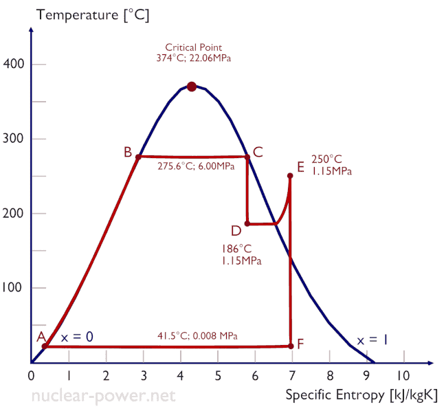
rankine cycle-minTypically most of nuclear power plants operates multi-stage condensing steam turbines. In these turbines the high-pressure stage receives steam (this steam is nearly saturated steam – x = 0.995 – point C at the figure; 6 MPa; 275.6°C) from a steam generator and exhaust it to moisture separator-reheater (point D). The steam must be reheated in order to avoid damages that could be caused to blades of steam turbine by low quality steam. The reheater heats the steam (point D) and then the steam is directed to the low-pressure stage of steam turbine, where expands (point E to F). The exhausted steam then condenses in the condenser and it is at a pressure well below atmospheric (absolute pressure of 0.008 MPa), and is in a partially condensed state (point F), typically of a quality near 90%.

In this case, steam generators, steam turbine, condensers and feedwater pumps constitute a heat engine, that is subject to the efficiency limitations imposed by the second law of thermodynamics. In ideal case (no friction, reversible processes, perfect design), this heat engine would have a Carnot efficiency of

η = 1 – Tcold/Thot = 1 – 315/549 = 42.6%

where the temperature of the hot reservoir is 275.6°C (548.7K), the temperature of the cold reservoir is 41.5°C (314.7K). But the nuclear power plant is the real heat engine, in which thermodynamic processes are somehow irreversible. They are not done infinitely slowly. In real devices (such as turbines, pumps, and compressors) a mechanical friction and heat losses cause further efficiency losses.

Therefore nuclear power plants usually have efficiency about 33%. In modern nuclear power plants the overall thermodynamic efficiency is about one-third (33%), so 3000 MWth of thermal power from the fission reaction is needed to generate 1000 MWe of electrical power.

Boiler Pressure
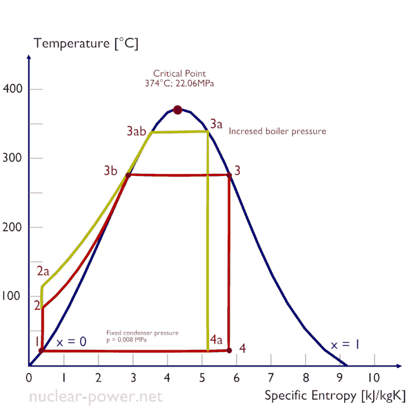
Rankine Cycle - boiler pressure
An increase in the boiler pressure is in the result limited by material of the reactor pressure vessel.

According to the Carnot’s principle higher efficiencies can be attained by increasing the temperature of the steam. But this requires an increase in pressures inside boilers or steam generators. However, metallurgical considerations place an upper limits on such pressures.  In order to prevent boiling of the primary coolant and to provide a subcooling margin (the difference between the pressurizer temperature and the highest temperature in the reactor core), pressures around 16 MPa are typical for PWRs. The reactor pressure vessel is the key component, which limits the thermal efficiency of each nuclear power plant, since the reactor vessel must withstand high pressures.

From this point of view, supercritical water reactors are considered a promising advancement for nuclear power plants because of its high thermal efficiency (~45 % vs. ~33 % for current LWRs). SCWRs are operated at supercritical pressure (i.e. greater than 22.1 MPa).

Condenser Pressure
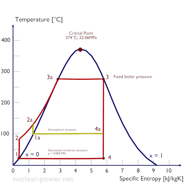
Rankine Cycle - condenser pressure
Decreasing the turbine exhaust pressure increases the net work per cycle but also decreses the vapor quality of outlet steam.

The case of the decrease in the average temperature at which energy is rejected, requires a decrease in the pressure inside condenser (i.e. the decrease in the saturation temperature). The lowest feasible condenser pressure is the saturation pressure corresponding to the ambient temperature (i.e. absolute pressure of 0.008 MPa, which corresponds to 41.5°C). The goal of maintaining the lowest practical turbine exhaust pressure is a primary reason for including the condenser in a thermal power plant. The condenser provides a vacuum that maximizes the energy extracted from the steam, resulting in a significant increase in net work and thermal efficiency. But also this parameter (condenser pressure) has its engineering limits:

  • Decreasing the turbine exhaust pressure decreases the vapor quality (or dryness fraction). At some point the expansion must be ended to avoid damages that could be caused to blades of steam turbine by low quality steam.
  • Decreasing the turbine exhaust pressure significantly increases the specific volume of exhausted steam, which requires huge blades in last rows of low-pressure stage of the steam turbine.

In a typical wet steam turbines, the exhausted steam condenses in the condenser and it is at a pressure well below atmospheric (absolute pressure of 0.008 MPa, which corresponds to 41.5°C). This steam is in a partially condensed state (point F), typically of a quality near 90%. Note that, there is always a temperature difference between (around ΔT = 14°C) the condenser temperature and the ambient temperature, which originates from finite size and efficiency of condensers.

 
References:
Heat Transfer:
  1. Fundamentals of Heat and Mass Transfer, 7th Edition. Theodore L. Bergman, Adrienne S. Lavine, Frank P. Incropera. John Wiley & Sons, Incorporated, 2011. ISBN: 9781118137253.
  2. Heat and Mass Transfer. Yunus A. Cengel. McGraw-Hill Education, 2011. ISBN: 9780071077866.
  3. U.S. Department of Energy, Thermodynamics, Heat Transfer and Fluid Flow. DOE Fundamentals Handbook, Volume 2 of 3. May 2016.

Nuclear and Reactor Physics:

  1. J. R. Lamarsh, Introduction to Nuclear Reactor Theory, 2nd ed., Addison-Wesley, Reading, MA (1983).
  2. J. R. Lamarsh, A. J. Baratta, Introduction to Nuclear Engineering, 3d ed., Prentice-Hall, 2001, ISBN: 0-201-82498-1.
  3. W. M. Stacey, Nuclear Reactor Physics, John Wiley & Sons, 2001, ISBN: 0- 471-39127-1.
  4. Glasstone, Sesonske. Nuclear Reactor Engineering: Reactor Systems Engineering, Springer; 4th edition, 1994, ISBN: 978-0412985317
  5. W.S.C. Williams. Nuclear and Particle Physics. Clarendon Press; 1 edition, 1991, ISBN: 978-0198520467
  6. G.R.Keepin. Physics of Nuclear Kinetics. Addison-Wesley Pub. Co; 1st edition, 1965
  7. Robert Reed Burn, Introduction to Nuclear Reactor Operation, 1988.
  8. U.S. Department of Energy, Nuclear Physics and Reactor Theory. DOE Fundamentals Handbook, Volume 1 and 2. January 1993.
  9. Paul Reuss, Neutron Physics. EDP Sciences, 2008. ISBN: 978-2759800414.

Advanced Reactor Physics:

  1. K. O. Ott, W. A. Bezella, Introductory Nuclear Reactor Statics, American Nuclear Society, Revised edition (1989), 1989, ISBN: 0-894-48033-2.
  2. K. O. Ott, R. J. Neuhold, Introductory Nuclear Reactor Dynamics, American Nuclear Society, 1985, ISBN: 0-894-48029-4.
  3. D. L. Hetrick, Dynamics of Nuclear Reactors, American Nuclear Society, 1993, ISBN: 0-894-48453-2.
  4. E. E. Lewis, W. F. Miller, Computational Methods of Neutron Transport, American Nuclear Society, 1993, ISBN: 0-894-48452-4.

See also:

Nuclear Engineering

We hope, this article, Heat Transfer, helps you. If so, give us a like in the sidebar. Main purpose of this website is to help the public to learn some interesting and important information about thermal engineering.
What is Application of Heat Transfer – Engineering – Definition

Application of Heat Transfer. Heat transfer is commonly encountered in engineering systems and other aspects of life, and one does not need to go very far to see some application areas of heat transfer. Thermal Engineering

Heat Transfer in Nuclear Engineering – Application

Heat transfer is commonly encountered in engineering systems and other aspects of life, and one does not need to go very far to see some application areas of heat transfer.

Continuity Equation - Flow Rates through Reactor
Example of flow rates in a reactor. It is an illustrative example, data do not represent any reactor design.

Detailed knowledge of heat transfer mechanisms is also essential for reactor engineers as well as all other engineers. A nuclear power plant (nuclear power station) looks like a standard thermal power station with one exception. The heat source in the nuclear power plant is a nuclear reactor. As is typical in all conventional thermal power stations the heat is used to generate steam which drives a steam turbine connected to a generator which produces electricity. But in nuclear power plants reactors produce enormous amount of heat (energy) in a small volume. The density of the energy generation is very large and this puts demands on its heat transfer system (reactor coolant system). Therefore we have to start by the reactor heat generation and removal from the reactor.

For a reactor to operate in a steady state, all of the heat released in the system must be removed as fast as it is produced. This is accomplished by passing a liquid or gaseous coolant through the core and through other regions where heat is generated. The heat transfer must be equal to or greater than the heat generation rate or overheating and possible damage to the fuel may occur. The nature and operation of this coolant system is one of the most important considerations in the design of a nuclear reactor.

It should be noted that from a strictly nuclear standpoint, there is theoretically no upper limit to the reactor thermal power, which can be attained by any critical reactor having sufficient excess of reactivity to overcome its negative temperature feedbacks. In each nuclear reactor, there is a direct proportionality between the neutron flux and the reactor thermal power. The term thermal power is usually used, because it means the rate at which heat is produced in the reactor core as the result of fissions in the fuel. Moreover, for a short period, a critical reactor does not need to have high excess of reactivity as in case of rapid reactivity excursions.

In short, almost any reactor is able to exceed the ability of heat removal of its coolant system. Beyond this point, the fuel would heat up and can reach very high temperatures. This situation must be avoided by reactor operator and by reactor safety systems. It is essential, that the heat generation – heat removal rate balance must be maintained to prevent these temperatures that might result in the failure of fuel or other structural materials. In reactor engineering, the thermal-hydraulics of nuclear reactors describe the effort involving the coupling of heat transfer and fluid dynamics to accomplish the desired heat removal rate from the core under both normal operation and accident conditions.

 
References:
Heat Transfer:
  1. Fundamentals of Heat and Mass Transfer, 7th Edition. Theodore L. Bergman, Adrienne S. Lavine, Frank P. Incropera. John Wiley & Sons, Incorporated, 2011. ISBN: 9781118137253.
  2. Heat and Mass Transfer. Yunus A. Cengel. McGraw-Hill Education, 2011. ISBN: 9780071077866.
  3. U.S. Department of Energy, Thermodynamics, Heat Transfer and Fluid Flow. DOE Fundamentals Handbook, Volume 2 of 3. May 2016.

Nuclear and Reactor Physics:

  1. J. R. Lamarsh, Introduction to Nuclear Reactor Theory, 2nd ed., Addison-Wesley, Reading, MA (1983).
  2. J. R. Lamarsh, A. J. Baratta, Introduction to Nuclear Engineering, 3d ed., Prentice-Hall, 2001, ISBN: 0-201-82498-1.
  3. W. M. Stacey, Nuclear Reactor Physics, John Wiley & Sons, 2001, ISBN: 0- 471-39127-1.
  4. Glasstone, Sesonske. Nuclear Reactor Engineering: Reactor Systems Engineering, Springer; 4th edition, 1994, ISBN: 978-0412985317
  5. W.S.C. Williams. Nuclear and Particle Physics. Clarendon Press; 1 edition, 1991, ISBN: 978-0198520467
  6. G.R.Keepin. Physics of Nuclear Kinetics. Addison-Wesley Pub. Co; 1st edition, 1965
  7. Robert Reed Burn, Introduction to Nuclear Reactor Operation, 1988.
  8. U.S. Department of Energy, Nuclear Physics and Reactor Theory. DOE Fundamentals Handbook, Volume 1 and 2. January 1993.
  9. Paul Reuss, Neutron Physics. EDP Sciences, 2008. ISBN: 978-2759800414.

Advanced Reactor Physics:

  1. K. O. Ott, W. A. Bezella, Introductory Nuclear Reactor Statics, American Nuclear Society, Revised edition (1989), 1989, ISBN: 0-894-48033-2.
  2. K. O. Ott, R. J. Neuhold, Introductory Nuclear Reactor Dynamics, American Nuclear Society, 1985, ISBN: 0-894-48029-4.
  3. D. L. Hetrick, Dynamics of Nuclear Reactors, American Nuclear Society, 1993, ISBN: 0-894-48453-2.
  4. E. E. Lewis, W. F. Miller, Computational Methods of Neutron Transport, American Nuclear Society, 1993, ISBN: 0-894-48452-4.

See also:

Heat Transfer

We hope, this article, Application of Heat Transfer – Engineering, helps you. If so, give us a like in the sidebar. Main purpose of this website is to help the public to learn some interesting and important information about thermal engineering.
What is Thermodynamics and Heat Transfer – Definition

Thermodynamics is the science that deals with energy production, storage, transfer and conversion. Thermodynamics and Heat Transfer

Thermodynamics and Heat Transfer

Rankine Cycle - Ts diagram
Rankine cycle – Ts diagram

Thermodynamics is the science that deals with energy production, storage, transfer and conversion. It studies the effects of work, heat and energy on a system as a system undergoes a process from one equilibrium state to another, and makes no reference to how long the process will take. But in engineering, we are often interested in the rate of heat transfer, which is the topic of the science of heat transfer. We can recall from thermodynamics that energy exists in various forms.

Heat transfer is primarily interested in heat, which is the form of energy that can be transferred from one system to another as a result of temperature difference. The engineering thermodynamics might better be named thermostatics, because it describes primarily the equilibrium states on either side of irreversible processes.

In engineering, the term convective heat transfer is used to describe the combined effects of conduction and fluid flow.  At this point, we have to add a new mechanism, which is known as advection (the transport of a substance by bulk motion). From the thermodynamic point of view, heat flows into a fluid by diffusion to increase its energy, the fluid then transfers (advects) this increased internal energy (not heat) from one location to another, and this is then followed by a second thermal interaction which transfers heat to a second body or system, again by diffusion.

Heat Transfer

Heat Transfer - mechanismsHeat transfer is an engineering discipline that concerns the generation, use, conversion, and exchange of heat (thermal energy) between physical systems.  In power engineering it determines key parameters and materials of heat exchangers. Heat transfer is usually classified into various mechanisms, such as:

  • Heat Conduction. Heat conduction, also called diffusion, occurs within a body or between two bodies in contact. It is the direct microscopic exchange of kinetic energy of particles through the boundary between two systems. When an object is at a different temperature from another body or its surroundings
  • Heat Convection. Heat convection depends on motion of mass from one region of space to another. Heat convection occurs when bulk flow of a fluid (gas or liquid) carries heat along with the flow of matter in the fluid.
  • Thermal Radiation. Radiation is heat transfer by electromagnetic radiation, such as sunshine, with no need for matter to be present in the space between bodies.
 
References:
Heat Transfer:
  1. Fundamentals of Heat and Mass Transfer, 7th Edition. Theodore L. Bergman, Adrienne S. Lavine, Frank P. Incropera. John Wiley & Sons, Incorporated, 2011. ISBN: 9781118137253.
  2. Heat and Mass Transfer. Yunus A. Cengel. McGraw-Hill Education, 2011. ISBN: 9780071077866.
  3. U.S. Department of Energy, Thermodynamics, Heat Transfer and Fluid Flow. DOE Fundamentals Handbook, Volume 2 of 3. May 2016.

Nuclear and Reactor Physics:

  1. J. R. Lamarsh, Introduction to Nuclear Reactor Theory, 2nd ed., Addison-Wesley, Reading, MA (1983).
  2. J. R. Lamarsh, A. J. Baratta, Introduction to Nuclear Engineering, 3d ed., Prentice-Hall, 2001, ISBN: 0-201-82498-1.
  3. W. M. Stacey, Nuclear Reactor Physics, John Wiley & Sons, 2001, ISBN: 0- 471-39127-1.
  4. Glasstone, Sesonske. Nuclear Reactor Engineering: Reactor Systems Engineering, Springer; 4th edition, 1994, ISBN: 978-0412985317
  5. W.S.C. Williams. Nuclear and Particle Physics. Clarendon Press; 1 edition, 1991, ISBN: 978-0198520467
  6. G.R.Keepin. Physics of Nuclear Kinetics. Addison-Wesley Pub. Co; 1st edition, 1965
  7. Robert Reed Burn, Introduction to Nuclear Reactor Operation, 1988.
  8. U.S. Department of Energy, Nuclear Physics and Reactor Theory. DOE Fundamentals Handbook, Volume 1 and 2. January 1993.
  9. Paul Reuss, Neutron Physics. EDP Sciences, 2008. ISBN: 978-2759800414.

Advanced Reactor Physics:

  1. K. O. Ott, W. A. Bezella, Introductory Nuclear Reactor Statics, American Nuclear Society, Revised edition (1989), 1989, ISBN: 0-894-48033-2.
  2. K. O. Ott, R. J. Neuhold, Introductory Nuclear Reactor Dynamics, American Nuclear Society, 1985, ISBN: 0-894-48029-4.
  3. D. L. Hetrick, Dynamics of Nuclear Reactors, American Nuclear Society, 1993, ISBN: 0-894-48453-2.
  4. E. E. Lewis, W. F. Miller, Computational Methods of Neutron Transport, American Nuclear Society, 1993, ISBN: 0-894-48452-4.

See also:

Heat Transfer

We hope, this article, Thermodynamics and Heat Transfer, helps you. If so, give us a like in the sidebar. Main purpose of this website is to help the public to learn some interesting and important information about thermal engineering.

What is Thermal Efficiency of Nuclear Power Plants – Definition

Thermal Efficiency of Nuclear Power Plants. In modern nuclear power plants the overall thermodynamic efficiency is about one-third (33%). Thermal Engineering

Thermal Efficiency of Nuclear Power Plants

The thermal efficiency of the conversion of thermal energy to work is primarily determined by the difference between the hot and cold temperature reservoirs. Thermal efficiency is improved if the heat input from the steam to the steam turbine is at as high a temperature as possible and the heat rejection in the condenser is at as low a temperature as possible. The high temperature in a light water reactor is usually limited by materials and pressure considerations and the sink temperature is limited by environment.

rankine cycle-minTypically most of nuclear power plants operates multi-stage condensing steam turbines. In these turbines the high-pressure stage receives steam (this steam is nearly saturated steam – x = 0.995 – point C at the figure; 6 MPa; 275.6°C) from a steam generator and exhaust it to moisture separator-reheater (point D). The steam must be reheated in order to avoid damages that could be caused to blades of steam turbine by low quality steam. The reheater heats the steam (point D) and then the steam is directed to the low-pressure stage of steam turbine, where expands (point E to F). The exhausted steam then condenses in the condenser and it is at a pressure well below atmospheric (absolute pressure of 0.008 MPa), and is in a partially condensed state (point F), typically of a quality near 90%.

In this case, steam generators, steam turbine, condensers and feedwater pumps constitute a heat engine, that is subject to the efficiency limitations imposed by the second law of thermodynamics. In ideal case (no friction, reversible processes, perfect design), this heat engine would have a Carnot efficiency of

η = 1 – Tcold/Thot = 1 – 315/549 = 42.6%

where the temperature of the hot reservoir is 275.6°C (548.7K), the temperature of the cold reservoir is 41.5°C (314.7K). But the nuclear power plant is the real heat engine, in which thermodynamic processes are somehow irreversible. They are not done infinitely slowly. In real devices (such as turbines, pumps, and compressors) a mechanical friction and heat losses cause further efficiency losses.

Therefore nuclear power plants usually have efficiency about 33%. In modern nuclear power plants the overall thermodynamic efficiency is about one-third (33%), so 3000 MWth of thermal power from the fission reaction is needed to generate 1000 MWe of electrical power.

Boiler Pressure

Rankine Cycle - boiler pressure
An increase in the boiler pressure is in the result limited by material of the reactor pressure vessel.

According to the Carnot’s principle higher efficiencies can be attained by increasing the temperature of the steam. But this requires an increase in pressures inside boilers or steam generators. However, metallurgical considerations place an upper limits on such pressures.  In order to prevent boiling of the primary coolant and to provide a subcooling margin (the difference between the pressurizer temperature and the highest temperature in the reactor core), pressures around 16 MPa are typical for PWRs. The reactor pressure vessel is the key component, which limits the thermal efficiency of each nuclear power plant, since the reactor vessel must withstand high pressures.

From this point of view, supercritical water reactors are considered a promising advancement for nuclear power plants because of its high thermal efficiency (~45 % vs. ~33 % for current LWRs). SCWRs are operated at supercritical pressure (i.e. greater than 22.1 MPa).

Condenser Pressure

Rankine Cycle - condenser pressure
Decreasing the turbine exhaust pressure increases the net work per cycle but also decreses the vapor quality of outlet steam.

The case of the decrease in the average temperature at which energy is rejected, requires a decrease in the pressure inside condenser (i.e. the decrease in the saturation temperature). The lowest feasible condenser pressure is the saturation pressure corresponding to the ambient temperature (i.e. absolute pressure of 0.008 MPa, which corresponds to 41.5°C). The goal of maintaining the lowest practical turbine exhaust pressure is a primary reason for including the condenser in a thermal power plant. The condenser provides a vacuum that maximizes the energy extracted from the steam, resulting in a significant increase in net work and thermal efficiency. But also this parameter (condenser pressure) has its engineering limits:

  • Decreasing the turbine exhaust pressure decreases the vapor quality (or dryness fraction). At some point the expansion must be ended to avoid damages that could be caused to blades of steam turbine by low quality steam.
  • Decreasing the turbine exhaust pressure significantly increases the specific volume of exhausted steam, which requires huge blades in last rows of low-pressure stage of the steam turbine.

In a typical wet steam turbines, the exhausted steam condenses in the condenser and it is at a pressure well below atmospheric (absolute pressure of 0.008 MPa, which corresponds to 41.5°C). This steam is in a partially condensed state (point F), typically of a quality near 90%. Note that, there is always a temperature difference between (around ΔT = 14°C) the condenser temperature and the ambient temperature, which originates from finite size and efficiency of condensers.

 
References:
Heat Transfer:
  1. Fundamentals of Heat and Mass Transfer, 7th Edition. Theodore L. Bergman, Adrienne S. Lavine, Frank P. Incropera. John Wiley & Sons, Incorporated, 2011. ISBN: 9781118137253.
  2. Heat and Mass Transfer. Yunus A. Cengel. McGraw-Hill Education, 2011. ISBN: 9780071077866.
  3. U.S. Department of Energy, Thermodynamics, Heat Transfer and Fluid Flow. DOE Fundamentals Handbook, Volume 2 of 3. May 2016.

Nuclear and Reactor Physics:

  1. J. R. Lamarsh, Introduction to Nuclear Reactor Theory, 2nd ed., Addison-Wesley, Reading, MA (1983).
  2. J. R. Lamarsh, A. J. Baratta, Introduction to Nuclear Engineering, 3d ed., Prentice-Hall, 2001, ISBN: 0-201-82498-1.
  3. W. M. Stacey, Nuclear Reactor Physics, John Wiley & Sons, 2001, ISBN: 0- 471-39127-1.
  4. Glasstone, Sesonske. Nuclear Reactor Engineering: Reactor Systems Engineering, Springer; 4th edition, 1994, ISBN: 978-0412985317
  5. W.S.C. Williams. Nuclear and Particle Physics. Clarendon Press; 1 edition, 1991, ISBN: 978-0198520467
  6. G.R.Keepin. Physics of Nuclear Kinetics. Addison-Wesley Pub. Co; 1st edition, 1965
  7. Robert Reed Burn, Introduction to Nuclear Reactor Operation, 1988.
  8. U.S. Department of Energy, Nuclear Physics and Reactor Theory. DOE Fundamentals Handbook, Volume 1 and 2. January 1993.
  9. Paul Reuss, Neutron Physics. EDP Sciences, 2008. ISBN: 978-2759800414.

Advanced Reactor Physics:

  1. K. O. Ott, W. A. Bezella, Introductory Nuclear Reactor Statics, American Nuclear Society, Revised edition (1989), 1989, ISBN: 0-894-48033-2.
  2. K. O. Ott, R. J. Neuhold, Introductory Nuclear Reactor Dynamics, American Nuclear Society, 1985, ISBN: 0-894-48029-4.
  3. D. L. Hetrick, Dynamics of Nuclear Reactors, American Nuclear Society, 1993, ISBN: 0-894-48453-2.
  4. E. E. Lewis, W. F. Miller, Computational Methods of Neutron Transport, American Nuclear Society, 1993, ISBN: 0-894-48452-4.

See also:

Thermal Efficiency

We hope, this article, Thermal Efficiency of Nuclear Power Plants, helps you. If so, give us a like in the sidebar. Main purpose of this website is to help the public to learn some interesting and important information about thermal engineering.
What is Introduction to Heat Transfer – Definition

Introduction to Heat Transfer. This article defines basic relationships and properties that are required to understand heat transfer, which is essential for reactor engineers. Thermal Engineering

Introduction to Heat Transfer

zeroth-law-of-thermodynamics-heatWhile internal energy refers to the total energy of all the molecules within the object, heat is the amount of energy flowing from one body to another spontaneously due to their temperature difference. Heat is a form of energy, but it is energy in transit. Heat is not a property of a system. However, the transfer of energy as heat occurs at the molecular level as a result of a temperature difference.

Consider a block of metal at high temperature, that consists of atoms that are oscillating intensely around their average positions. At low temperatures, the atoms continue to oscillate, but with less intensity. If a hotter block of metal is put in contact with a cooler block, the intensely oscillating atoms at the edge of the hotter block gives off its kinetic energy to the less oscillating atoms at the edge of the cool block. In this case there is energy transfer between these two blocks and heat flows from the hotter to the cooler block by this random vibrations.

 
Thermal Energy in Microscopic Scale
Internal energy involves energy on the microscopic scale. It may be divided into microscopic potential energy, Upot, and microscopic kinetic energy, Ukin, components:

U = Upot + Ukin

Microscopic Energy - Internal Energywhere the microscopic kinetic energy, Ukin, involves the motions of all the system’s particles with respect to the center-of-mass frame. For an ideal monatomic gas, this is just the translational kinetic energy of the linear motion of the atoms. Monoatomic particles do not rotate or vibrate. The behavior of the system is well described by kinetic theory of gases. Kinetic theory is based on the fact that during an elastic collision between a molecule with high kinetic energy and one with low kinetic energy, part of energy will transfer to the molecule of lower kinetic energy. However, for polyatomic gases there isrotational and vibrational kinetic energy as well.

The microscopic potential energy, Upot, involves the chemical bonds between the atoms that make up the molecules, binding forces in the nucleus and also the physical force fields within the system (e.g. electric or magnetic fields).

In liquids and solids there is significant component of potential energy associated with the intermolecular attractive forces.

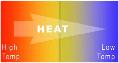
In general, when two objects are brought into thermal contact, heat will flow between them until they come into equilibrium with each other.  When a temperature difference does exist heat flows spontaneously from the warmer system to the colder system. Heat transfer occurs by conduction or by thermal radiation. When the flow of heat stops, they are said to be at the same temperature. They are then said to be in thermal equilibrium.

As with work, the amount of heat transferred depends upon the path and not simply on the initial and final conditions of the system. There are actually many ways to take the gas from state i to state f.

Also, as with work, it is important to distinguish between heat added to a system from its surroundings and heat removed from a system to its surroundings. Q is positive for heat added to the system, so if heat leaves the system, Q is negative. Because W in the equation is the work done by the system, then if work is done on the system, W will be negative and Eint will increase.

The symbol q is sometimes used to indicate the heat added to or removed from a system per unit mass. It equals the total heat (Q) added or removed divided by the mass (m).

Distinguishing Temperature, Heat, and Internal Energy

Using the kinetic theory, a clear distinction between these three properties can be made.

  • Temperature is related to the kinetic energies of the molecules of a material. It is the average kinetic energy of individual molecules.
  • Internal energy refers to the total energy of all the molecules within the object. It is an extensive property, therefore when two equal-mass hot ingots of steel may have the same temperature, but two of them have twice as much internal energy as one does.
  • Finally, heat is the amount of energy flowing from one body to another spontaneously due to their temperature difference.

It must be added, when a temperature difference does exist heat flows spontaneously from the warmer system to the colder system. Thus, if a 5 kg cube of steel at 100°C is placed in contact with a 500 kg cube of steel at 20°C, heat flows from the cube at 300°C to the cube at 20°C even though the internal energy of the 20°C cube is much greater because there is so much more of it.

A particularly important concept is thermodynamic equilibrium. In general, when two objects are brought into thermal contact, heat will flow between them until they come into equilibrium with each other.

 
Thermal Energy in Microscopic Scale
Internal energy involves energy on the microscopic scale. It may be divided into microscopic potential energy, Upot, and microscopic kinetic energy, Ukin, components:

U = Upot + Ukin

Microscopic Energy - Internal Energywhere the microscopic kinetic energy, Ukin, involves the motions of all the system’s particles with respect to the center-of-mass frame. For an ideal monatomic gas, this is just the translational kinetic energy of the linear motion of the atoms. Monoatomic particles do not rotate or vibrate. The behavior of the system is well described by kinetic theory of gases. Kinetic theory is based on the fact that during an elastic collision between a molecule with high kinetic energy and one with low kinetic energy, part of energy will transfer to the molecule of lower kinetic energy. However, for polyatomic gases there isrotational and vibrational kinetic energy as well.

The microscopic potential energy, Upot, involves the chemical bonds between the atoms that make up the molecules, binding forces in the nucleus and also the physical force fields within the system (e.g. electric or magnetic fields).

In liquids and solids there is significant component of potential energy associated with the intermolecular attractive forces.

Heat Flux Density – Thermal Flux

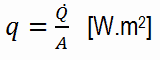
The rate of heat transfer per unit area normal to the direction of heat transfer is called heat flux. Sometimes it is also referred to as heat flux density. In SI its units are watts per square metre (W.m−2). It has both a direction and a magnitude, and so it is a vector quantity. The average heat flux is expressed as:

heat flux density - equation

where A is the heat transfer area. The unit of heat flux in English units is Btu/h·ft2. Note that heat flux may vary with time as well as position on a surface.

In nuclear reactors, limitations of the local heat flux is of the highest importance for reactor safety. Since nuclear fuel consist of fuel rods, the heat flux is there defined in units of W/cm (local linear heat flux density) or kW/rod (power per fuel rod).

See also: Heat Flux Density

 
References:
Heat Transfer:
  1. Fundamentals of Heat and Mass Transfer, 7th Edition. Theodore L. Bergman, Adrienne S. Lavine, Frank P. Incropera. John Wiley & Sons, Incorporated, 2011. ISBN: 9781118137253.
  2. Heat and Mass Transfer. Yunus A. Cengel. McGraw-Hill Education, 2011. ISBN: 9780071077866.
  3. Fundamentals of Heat and Mass Transfer. C. P. Kothandaraman. New Age International, 2006, ISBN: 9788122417722.
  4. U.S. Department of Energy, Thermodynamics, Heat Transfer and Fluid Flow. DOE Fundamentals Handbook, Volume 2 of 3. May 2016.

Nuclear and Reactor Physics:

  1. J. R. Lamarsh, Introduction to Nuclear Reactor Theory, 2nd ed., Addison-Wesley, Reading, MA (1983).
  2. J. R. Lamarsh, A. J. Baratta, Introduction to Nuclear Engineering, 3d ed., Prentice-Hall, 2001, ISBN: 0-201-82498-1.
  3. W. M. Stacey, Nuclear Reactor Physics, John Wiley & Sons, 2001, ISBN: 0- 471-39127-1.
  4. Glasstone, Sesonske. Nuclear Reactor Engineering: Reactor Systems Engineering, Springer; 4th edition, 1994, ISBN: 978-0412985317
  5. W.S.C. Williams. Nuclear and Particle Physics. Clarendon Press; 1 edition, 1991, ISBN: 978-0198520467
  6. G.R.Keepin. Physics of Nuclear Kinetics. Addison-Wesley Pub. Co; 1st edition, 1965
  7. Robert Reed Burn, Introduction to Nuclear Reactor Operation, 1988.
  8. U.S. Department of Energy, Nuclear Physics and Reactor Theory. DOE Fundamentals Handbook, Volume 1 and 2. January 1993.
  9. Paul Reuss, Neutron Physics. EDP Sciences, 2008. ISBN: 978-2759800414.

Advanced Reactor Physics:

  1. K. O. Ott, W. A. Bezella, Introductory Nuclear Reactor Statics, American Nuclear Society, Revised edition (1989), 1989, ISBN: 0-894-48033-2.
  2. K. O. Ott, R. J. Neuhold, Introductory Nuclear Reactor Dynamics, American Nuclear Society, 1985, ISBN: 0-894-48029-4.
  3. D. L. Hetrick, Dynamics of Nuclear Reactors, American Nuclear Society, 1993, ISBN: 0-894-48453-2.
  4. E. E. Lewis, W. F. Miller, Computational Methods of Neutron Transport, American Nuclear Society, 1993, ISBN: 0-894-48452-4.

See also:

Heat Transfer

We hope, this article, Introduction to Heat Transfer, helps you. If so, give us a like in the sidebar. Main purpose of this website is to help the public to learn some interesting and important information about thermal engineering.
What is Heat in Physics – Heat – Definition

Heat is the amount of energy flowing from one body to another spontaneously due to their temperature difference. Heat in Physics – Definition of Heat

Definition of Heat

zeroth-law-of-thermodynamics-heatWhile internal energy refers to the total energy of all the molecules within the object, heat is the amount of energy flowing from one body to another spontaneously due to their temperature difference. Heat is a form of energy, but it is energy in transit. Heat is not a property of a system. However, the transfer of energy as heat occurs at the molecular level as a result of a temperature difference.

Consider a block of metal at high temperature, that consists of atoms that are oscillating intensely around their average positions. At low temperatures, the atoms continue to oscillate, but with less intensity. If a hotter block of metal is put in contact with a cooler block, the intensely oscillating atoms at the edge of the hotter block gives off its kinetic energy to the less oscillating atoms at the edge of the cool block. In this case there is energy transfer between these two blocks and heat flows from the hotter to the cooler block by this random vibrations.

 
Thermal Energy in Microscopic Scale
Internal energy involves energy on the microscopic scale. It may be divided into microscopic potential energy, Upot, and microscopic kinetic energy, Ukin, components:

U = Upot + Ukin

Microscopic Energy - Internal Energywhere the microscopic kinetic energy, Ukin, involves the motions of all the system’s particles with respect to the center-of-mass frame. For an ideal monatomic gas, this is just the translational kinetic energy of the linear motion of the atoms. Monoatomic particles do not rotate or vibrate. The behavior of the system is well described by kinetic theory of gases. Kinetic theory is based on the fact that during an elastic collision between a molecule with high kinetic energy and one with low kinetic energy, part of energy will transfer to the molecule of lower kinetic energy. However, for polyatomic gases there isrotational and vibrational kinetic energy as well.

The microscopic potential energy, Upot, involves the chemical bonds between the atoms that make up the molecules, binding forces in the nucleus and also the physical force fields within the system (e.g. electric or magnetic fields).

In liquids and solids there is significant component of potential energy associated with the intermolecular attractive forces.

In general, when two objects are brought into thermal contact, heat will flow between them until they come into equilibrium with each other.  When a temperature difference does exist heat flows spontaneously from the warmer system to the colder system. Heat transfer occurs by conduction or by thermal radiation. When the flow of heat stops, they are said to be at the same temperature. They are then said to be in thermal equilibrium.

As with work, the amount of heat transferred depends upon the path and not simply on the initial and final conditions of the system. There are actually many ways to take the gas from state i to state f.

Also, as with work, it is important to distinguish between heat added to a system from its surroundings and heat removed from a system to its surroundings. Q is positive for heat added to the system, so if heat leaves the system, Q is negative. Because W in the equation is the work done by the system, then if work is done on the system, W will be negative and Eint will increase.

The symbol q is sometimes used to indicate the heat added to or removed from a system per unit mass. It equals the total heat (Q) added or removed divided by the mass (m).

Distinguishing Temperature, Heat, and Internal Energy

Using the kinetic theory, a clear distinction between these three properties can be made.

  • Temperature is related to the kinetic energies of the molecules of a material. It is the average kinetic energy of individual molecules.
  • Internal energy refers to the total energy of all the molecules within the object. It is an extensive property, therefore when two equal-mass hot ingots of steel may have the same temperature, but two of them have twice as much internal energy as one does.
  • Finally, heat is the amount of energy flowing from one body to another spontaneously due to their temperature difference.

It must be added, when a temperature difference does exist heat flows spontaneously from the warmer system to the colder system. Thus, if a 5 kg cube of steel at 100°C is placed in contact with a 500 kg cube of steel at 20°C, heat flows from the cube at 300°C to the cube at 20°C even though the internal energy of the 20°C cube is much greater because there is so much more of it.

A particularly important concept is thermodynamic equilibrium. In general, when two objects are brought into thermal contact, heat will flow between them until they come into equilibrium with each other.

 
Thermal Energy in Microscopic Scale
Internal energy involves energy on the microscopic scale. It may be divided into microscopic potential energy, Upot, and microscopic kinetic energy, Ukin, components:

U = Upot + Ukin

Microscopic Energy - Internal Energywhere the microscopic kinetic energy, Ukin, involves the motions of all the system’s particles with respect to the center-of-mass frame. For an ideal monatomic gas, this is just the translational kinetic energy of the linear motion of the atoms. Monoatomic particles do not rotate or vibrate. The behavior of the system is well described by kinetic theory of gases. Kinetic theory is based on the fact that during an elastic collision between a molecule with high kinetic energy and one with low kinetic energy, part of energy will transfer to the molecule of lower kinetic energy. However, for polyatomic gases there isrotational and vibrational kinetic energy as well.

The microscopic potential energy, Upot, involves the chemical bonds between the atoms that make up the molecules, binding forces in the nucleus and also the physical force fields within the system (e.g. electric or magnetic fields).

In liquids and solids there is significant component of potential energy associated with the intermolecular attractive forces.

Example – Evaporation of water at atmospheric pressure

Calculate heat required to evaporate 1 kg of water at the atmospheric pressure (p = 1.0133 bar) and at the temperature of 100°C.

Solution:

Since these parameters corresponds to the saturated liquid state, only latent heat of vaporization of 1 kg of water is required. From steam tables, the latent heat of vaporization is L = 2257 kJ/kg. Therefore the heat required is equal to:

ΔH = 2257 kJ

Note that the initial specific enthalpy h1 = 419 kJ/kg, whereas the final specific enthalpy will be h2 = 2676 kJ/kg. The specific enthalpy of low-pressure dry steam is very similar to the specific enthalpy of high-pressure dry steam, despite the fact they have different temperatures.

Example – Evaporation of water at high pressure

Calculate heat required to evaporate 1 kg of feedwater at the pressure of 6 MPa (p = 60 bar) and at the temperature of 275.6°C (saturation temperature).

Solution:

Since these parameters corresponds to the saturated liquid state, only latent heat of vaporization of 1 kg of water is required. From steam tables, the latent heat of vaporization is L = 1571 kJ/kg. Therefore the heat required is equal to:

ΔH = 1571 kJ

Note that the initial specific enthalpy h1 = 1214 kJ/kg, whereas the final specific enthalpy will be h2 = 2785 kJ/kg.

 
References:
Heat Transfer:
  1. Fundamentals of Heat and Mass Transfer, 7th Edition. Theodore L. Bergman, Adrienne S. Lavine, Frank P. Incropera. John Wiley & Sons, Incorporated, 2011. ISBN: 9781118137253.
  2. Heat and Mass Transfer. Yunus A. Cengel. McGraw-Hill Education, 2011. ISBN: 9780071077866.
  3. Fundamentals of Heat and Mass Transfer. C. P. Kothandaraman. New Age International, 2006, ISBN: 9788122417722.
  4. U.S. Department of Energy, Thermodynamics, Heat Transfer and Fluid Flow. DOE Fundamentals Handbook, Volume 2 of 3. May 2016.

Nuclear and Reactor Physics:

  1. J. R. Lamarsh, Introduction to Nuclear Reactor Theory, 2nd ed., Addison-Wesley, Reading, MA (1983).
  2. J. R. Lamarsh, A. J. Baratta, Introduction to Nuclear Engineering, 3d ed., Prentice-Hall, 2001, ISBN: 0-201-82498-1.
  3. W. M. Stacey, Nuclear Reactor Physics, John Wiley & Sons, 2001, ISBN: 0- 471-39127-1.
  4. Glasstone, Sesonske. Nuclear Reactor Engineering: Reactor Systems Engineering, Springer; 4th edition, 1994, ISBN: 978-0412985317
  5. W.S.C. Williams. Nuclear and Particle Physics. Clarendon Press; 1 edition, 1991, ISBN: 978-0198520467
  6. G.R.Keepin. Physics of Nuclear Kinetics. Addison-Wesley Pub. Co; 1st edition, 1965
  7. Robert Reed Burn, Introduction to Nuclear Reactor Operation, 1988.
  8. U.S. Department of Energy, Nuclear Physics and Reactor Theory. DOE Fundamentals Handbook, Volume 1 and 2. January 1993.
  9. Paul Reuss, Neutron Physics. EDP Sciences, 2008. ISBN: 978-2759800414.

Advanced Reactor Physics:

  1. K. O. Ott, W. A. Bezella, Introductory Nuclear Reactor Statics, American Nuclear Society, Revised edition (1989), 1989, ISBN: 0-894-48033-2.
  2. K. O. Ott, R. J. Neuhold, Introductory Nuclear Reactor Dynamics, American Nuclear Society, 1985, ISBN: 0-894-48029-4.
  3. D. L. Hetrick, Dynamics of Nuclear Reactors, American Nuclear Society, 1993, ISBN: 0-894-48453-2.
  4. E. E. Lewis, W. F. Miller, Computational Methods of Neutron Transport, American Nuclear Society, 1993, ISBN: 0-894-48452-4.

See also:

Basics of Heat Transfer

We hope, this article, Heat in Physics – Heat, helps you. If so, give us a like in the sidebar. Main purpose of this website is to help the public to learn some interesting and important information about thermal engineering.
What is Heat Flux Density – Thermal Flux – Definition

The rate of heat transfer per unit area normal to the direction of heat transfer is called heat flux. Sometimes it is also referred to as heat flux density. Thermal Engineering

Heat Flux Density – Thermal Flux

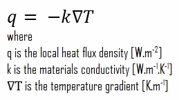
The rate of heat transfer per unit area normal to the direction of heat transfer is called heat flux. Sometimes it is also referred to as heat flux density. In SI its units are watts per square metre (W.m−2). It has both a direction and a magnitude, and so it is a vector quantity. The average heat flux is expressed as:

heat flux density - equation

where A is the heat transfer area. The unit of heat flux in English units is Btu/h·ft2. Note that heat flux may vary with time as well as position on a surface.

In nuclear reactors, limitations of the local heat flux is of the highest importance for reactor safety. Since nuclear fuel consist of fuel rods, the heat flux is there defined in units of W/cm (local linear heat flux) or kW/rod (power per fuel rod).

 
Microscopic view of heat conduction
Consider, for example, heat conduction, which is one of three machanisms of heat transfer.

Consider a block of metal at high temperature, that consists of atoms that are oscillating intensely around their average positions. At low temperatures, the atoms continue to oscillate, but with less intensity. If a hotter block of metal is put in contact with a cooler block, the intensely oscillating atoms at the edge of the hotter block gives off its kinetic energy to the less oscillating atoms at the edge of the cool block. In this case there is energy transfer between these two blocks and heat flows from the hotter to the cooler block by this random vibrations.

Heat Flux Measurement

The measurement of heat flux can be performed in a few different manners.

  • Measurement based on the temperature difference. A commonly known, but often impractical, method is performed by measuring a temperature difference over a piece of material with known thermal conductivity. This method assumes that the material’s thermal conductivity is well known. This method is analogous to a standard way to measure an electric current, where one measures the voltage drop over a known resistor.
  • Measurement based on the use of the heat flux sensor. Heat flux can be directly measured via heat flux sensors or heat flux transducers. The most common type of heat flux sensor is a differential temperature thermopile which operates on essentially the same principal as the first measurement method. A heat flux sensor should measure the local heat flux density in one direction. The result is expressed in watts per square meter. This measurement has the advantage in that the thermal conductivity does not need to be a known parameter.

Example – Heat flux through a window

Example - Heat Flux - Thermal ConductionHeat loss through windows

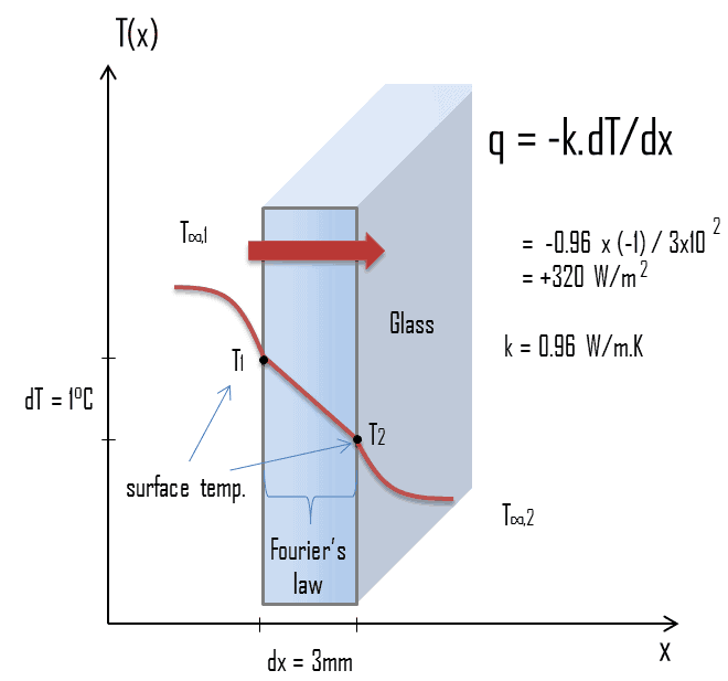
A major source of heat loss from a house is through the windows. Calculate the rate of heat flux through a glass window 1.5 m x 1.0 m in area and 3.0 mm thick, if the temperatures at the inner and outer surfaces are 14.0°C and 13.0°C, respectively. Calculate the heat flux through this window.

Solution:

At this point, we know the temperatures at the surfaces of material. These temperatures are given also by conditions inside the house and outside the house. In this case, heat flows by conduction through the glass from the higher inside temperature to the lower outside temperature. We use the heat conduction equation:

Heat loss through window - equation

We assume that the thermal conductivity of a common glass is k = 0.96 W/m.K.

The heat flux will then be:

q = 0.96 [W/m.K] x 1 [K] / 3.0 x 10-3 [m] = 320 W/m2

The total heat loss through this window will be:

qloss = q . A = 320 x 1.5 x 1.0 = 480W

Critical Heat Flux

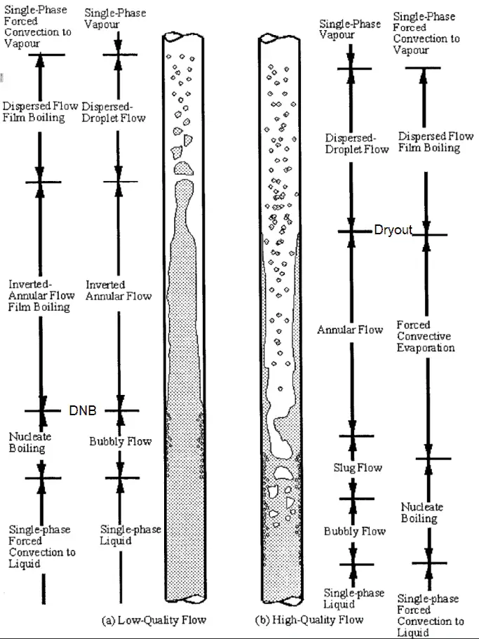
Dryout vs. DNBAs was written, in nuclear reactors, limitations of the local heat flux is of the highest importance for reactor safety. For pressurized water reactors and also for boiling water reactors, there are thermal-hydraulic phenomena, which cause a sudden decrease in the efficiency of heat transfer (more precisely in the heat transfer coefficient). These phenomena occur at certain value of heat flux, known as the “critical heat flux”. The phenomena, that cause the deterioration of heat transfer are different for PWRs and for BWRs.

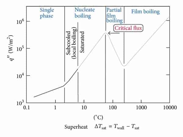
In both types of reactors, the problem is more or less associated with departure from nucleate boiling. The nucleate boiling heat flux cannot be increased indefinitely. At some value, we call it the “critical heat flux” (CHF), the steam produced can form an insulating layer over the surface, which in turn deteriorates the heat transfer coefficient. Immediately after the critical heat flux has been reached, boiling become unstable and film boiling occurs. The transition from nucleate boiling to film boiling is known as the “boiling crisis”. As was written, the phenomena, that cause the deterioration of heat transfer are different for PWRs and for BWRs.

  • Dryout. In BWRs, this phenomenon is known as the “dryout” and it is directly associated with changes in flow pattern during evaporation in the high-quality region. At given combinations of flow rate through a channel, pressure, flow quality, and linear heat rate, the wall liquid film may exhaust and the wall may be dried out. At normal, the fuel surface is effectively cooled by boiling coolant. However when the heat flux exceeds a critical value (CHF – critical heat flux) the flow pattern may reach the dryout conditions (thin film of liquid disappears). The heat transfer from the fuel surface into the coolant is deteriorated, with the result of a drastically increased fuel surface temperature. In the high-quality region, the crisis occurs at a lower heat flux. Since the flow velocity in the vapor core is high, post-CHF heat transfer is much better than for low-quality critical flux (i.e. for PWRs temperature rises are higher and more rapid).
  • critical heat flux and DNB (Departure from Nucleate Boiling)
    If the heat flux of a boiling system is higher than the critical heat flux then DNB (Departure from Nucleate Boiling) may occur.

    Departure from Nucleate Boiling. In case of PWRs, the critical safety issue is named DNB (departure from nucleate boiling), which causes the formation of a local vapor layer, causing a dramatic reduction in heat transfer capability. This phenomenon occurs in the subcooled or low-quality region. The behaviour of the boiling crisis depends on many flow conditions (pressure, temperature, flow rate), but the boiling crisis occurs at a relatively high heat fluxes and appears to be associated with the cloud of bubbles, adjacent to the surface. These bubbles or film of vapor reduces the amount of incoming water. Since this phenomenon deteriorates the heat transfer coefficient and the heat flux remains, heat then accumulates in the fuel rod causing dramatic rise of cladding and fuel temperature. Simply, a very high temperature difference is required to transfer the critical heat flux being produced from the surface of the fuel rod to the reactor coolant (through vapor layer). In case of PWRs, the critical flow is inverted annular flow, while in BWRs, the critical flow is usually annular flow. The difference in flow regime between post-dryout flow and post-DNB flow is depicted in the figure. In PWRs at normal operation the flow is considered to be single-phase. But a great deal of study has been performed on the nature of two-phase flow in case of transients and accidents (such as the loss-of-coolant accident – LOCA or trip of RCPs), which are of importance in reactor safety and in must be proved and declared in the Safety Analysis Report (SAR).

 
References:
Heat Transfer:
  1. Fundamentals of Heat and Mass Transfer, 7th Edition. Theodore L. Bergman, Adrienne S. Lavine, Frank P. Incropera. John Wiley & Sons, Incorporated, 2011. ISBN: 9781118137253.
  2. Heat and Mass Transfer. Yunus A. Cengel. McGraw-Hill Education, 2011. ISBN: 9780071077866.
  3. Fundamentals of Heat and Mass Transfer. C. P. Kothandaraman. New Age International, 2006, ISBN: 9788122417722.
  4. U.S. Department of Energy, Thermodynamics, Heat Transfer and Fluid Flow. DOE Fundamentals Handbook, Volume 2 of 3. May 2016.

Nuclear and Reactor Physics:

  1. J. R. Lamarsh, Introduction to Nuclear Reactor Theory, 2nd ed., Addison-Wesley, Reading, MA (1983).
  2. J. R. Lamarsh, A. J. Baratta, Introduction to Nuclear Engineering, 3d ed., Prentice-Hall, 2001, ISBN: 0-201-82498-1.
  3. W. M. Stacey, Nuclear Reactor Physics, John Wiley & Sons, 2001, ISBN: 0- 471-39127-1.
  4. Glasstone, Sesonske. Nuclear Reactor Engineering: Reactor Systems Engineering, Springer; 4th edition, 1994, ISBN: 978-0412985317
  5. W.S.C. Williams. Nuclear and Particle Physics. Clarendon Press; 1 edition, 1991, ISBN: 978-0198520467
  6. G.R.Keepin. Physics of Nuclear Kinetics. Addison-Wesley Pub. Co; 1st edition, 1965
  7. Robert Reed Burn, Introduction to Nuclear Reactor Operation, 1988.
  8. U.S. Department of Energy, Nuclear Physics and Reactor Theory. DOE Fundamentals Handbook, Volume 1 and 2. January 1993.
  9. Paul Reuss, Neutron Physics. EDP Sciences, 2008. ISBN: 978-2759800414.

Advanced Reactor Physics:

  1. K. O. Ott, W. A. Bezella, Introductory Nuclear Reactor Statics, American Nuclear Society, Revised edition (1989), 1989, ISBN: 0-894-48033-2.
  2. K. O. Ott, R. J. Neuhold, Introductory Nuclear Reactor Dynamics, American Nuclear Society, 1985, ISBN: 0-894-48029-4.
  3. D. L. Hetrick, Dynamics of Nuclear Reactors, American Nuclear Society, 1993, ISBN: 0-894-48453-2.
  4. E. E. Lewis, W. F. Miller, Computational Methods of Neutron Transport, American Nuclear Society, 1993, ISBN: 0-894-48452-4.

See also:

Basics of Heat Transfer

We hope, this article, Heat Flux Density – Thermal Flux, helps you. If so, give us a like in the sidebar. Main purpose of this website is to help the public to learn some interesting and important information about thermal engineering.
What is Heat Flux Measurement – Definition

The measurement of heat flux can be performed in a few different manners. Some methods are based on the use of the heat flux sensor. Heat Flux Measurement

Heat Flux Measurement

The measurement of heat flux can be performed in a few different manners.

  • Measurement based on the temperature difference. A commonly known, but often impractical, method is performed by measuring a temperature difference over a piece of material with known thermal conductivity. This method assumes that the material’s thermal conductivity is well known. This method is analogous to a standard way to measure an electric current, where one measures the voltage drop over a known resistor.
  • Measurement based on the use of the heat flux sensor. Heat flux can be directly measured via heat flux sensors or heat flux transducers. The most common type of heat flux sensor is a differential temperature thermopile which operates on essentially the same principal as the first measurement method. A heat flux sensor should measure the local heat flux density in one direction. The result is expressed in watts per square meter. This measurement has the advantage in that the thermal conductivity does not need to be a known parameter.

Heat Flux Density – Thermal Flux

The rate of heat transfer per unit area normal to the direction of heat transfer is called heat flux. Sometimes it is also referred to as heat flux density. In SI its units are watts per square metre (W.m−2). It has both a direction and a magnitude, and so it is a vector quantity. The average heat flux is expressed as:

heat flux density - equation

where A is the heat transfer area. The unit of heat flux in English units is Btu/h·ft2. Note that heat flux may vary with time as well as position on a surface.

In nuclear reactors, limitations of the local heat flux is of the highest importance for reactor safety. Since nuclear fuel consist of fuel rods, the heat flux is there defined in units of W/cm (local linear heat flux) or kW/rod (power per fuel rod).

 
References:
Heat Transfer:
  1. Fundamentals of Heat and Mass Transfer, 7th Edition. Theodore L. Bergman, Adrienne S. Lavine, Frank P. Incropera. John Wiley & Sons, Incorporated, 2011. ISBN: 9781118137253.
  2. Heat and Mass Transfer. Yunus A. Cengel. McGraw-Hill Education, 2011. ISBN: 9780071077866.
  3. Fundamentals of Heat and Mass Transfer. C. P. Kothandaraman. New Age International, 2006, ISBN: 9788122417722.
  4. U.S. Department of Energy, Thermodynamics, Heat Transfer and Fluid Flow. DOE Fundamentals Handbook, Volume 2 of 3. May 2016.

Nuclear and Reactor Physics:

  1. J. R. Lamarsh, Introduction to Nuclear Reactor Theory, 2nd ed., Addison-Wesley, Reading, MA (1983).
  2. J. R. Lamarsh, A. J. Baratta, Introduction to Nuclear Engineering, 3d ed., Prentice-Hall, 2001, ISBN: 0-201-82498-1.
  3. W. M. Stacey, Nuclear Reactor Physics, John Wiley & Sons, 2001, ISBN: 0- 471-39127-1.
  4. Glasstone, Sesonske. Nuclear Reactor Engineering: Reactor Systems Engineering, Springer; 4th edition, 1994, ISBN: 978-0412985317
  5. W.S.C. Williams. Nuclear and Particle Physics. Clarendon Press; 1 edition, 1991, ISBN: 978-0198520467
  6. G.R.Keepin. Physics of Nuclear Kinetics. Addison-Wesley Pub. Co; 1st edition, 1965
  7. Robert Reed Burn, Introduction to Nuclear Reactor Operation, 1988.
  8. U.S. Department of Energy, Nuclear Physics and Reactor Theory. DOE Fundamentals Handbook, Volume 1 and 2. January 1993.
  9. Paul Reuss, Neutron Physics. EDP Sciences, 2008. ISBN: 978-2759800414.

Advanced Reactor Physics:

  1. K. O. Ott, W. A. Bezella, Introductory Nuclear Reactor Statics, American Nuclear Society, Revised edition (1989), 1989, ISBN: 0-894-48033-2.
  2. K. O. Ott, R. J. Neuhold, Introductory Nuclear Reactor Dynamics, American Nuclear Society, 1985, ISBN: 0-894-48029-4.
  3. D. L. Hetrick, Dynamics of Nuclear Reactors, American Nuclear Society, 1993, ISBN: 0-894-48453-2.
  4. E. E. Lewis, W. F. Miller, Computational Methods of Neutron Transport, American Nuclear Society, 1993, ISBN: 0-894-48452-4.

See also:

Heat Flux

We hope, this article, Heat Flux Measurement, helps you. If so, give us a like in the sidebar. Main purpose of this website is to help the public to learn some interesting and important information about thermal engineering.
What is Example: Heat flux through Window – Definition

Heat flux through windows. A major source of heat loss from a house is through the windows. Calculate the rate of heat flux through a glass window 1.5 m x 1.0 m. Thermal Engineering

Example – Heat flux through a window

Example - Heat Flux - Thermal ConductionHeat loss through windows

A major source of heat loss from a house is through the windows. Calculate the rate of heat flux through a glass window 1.5 m x 1.0 m in area and 3.0 mm thick, if the temperatures at the inner and outer surfaces are 14.0°C and 13.0°C, respectively. Calculate the heat flux through this window.

Solution:

At this point, we know the temperatures at the surfaces of material. These temperatures are given also by conditions inside the house and outside the house. In this case, heat flows by conduction through the glass from the higher inside temperature to the lower outside temperature. We use the heat conduction equation:

Heat loss through window - equation

We assume that the thermal conductivity of a common glass is k = 0.96 W/m.K.

The heat flux will then be:

q = 0.96 [W/m.K] x 1 [K] / 3.0 x 10-3 [m] = 320 W/m2

The total heat loss through this window will be:

qloss = q . A = 320 x 1.5 x 1.0 = 480W

Heat Flux Density – Thermal Flux

The rate of heat transfer per unit area normal to the direction of heat transfer is called heat flux. Sometimes it is also referred to as heat flux density. In SI its units are watts per square metre (W.m−2). It has both a direction and a magnitude, and so it is a vector quantity. The average heat flux is expressed as:

heat flux density - equation

where A is the heat transfer area. The unit of heat flux in English units is Btu/h·ft2. Note that heat flux may vary with time as well as position on a surface.

In nuclear reactors, limitations of the local heat flux is of the highest importance for reactor safety. Since nuclear fuel consist of fuel rods, the heat flux is there defined in units of W/cm (local linear heat flux) or kW/rod (power per fuel rod).

 
References:
Heat Transfer:
  1. Fundamentals of Heat and Mass Transfer, 7th Edition. Theodore L. Bergman, Adrienne S. Lavine, Frank P. Incropera. John Wiley & Sons, Incorporated, 2011. ISBN: 9781118137253.
  2. Heat and Mass Transfer. Yunus A. Cengel. McGraw-Hill Education, 2011. ISBN: 9780071077866.
  3. Fundamentals of Heat and Mass Transfer. C. P. Kothandaraman. New Age International, 2006, ISBN: 9788122417722.
  4. U.S. Department of Energy, Thermodynamics, Heat Transfer and Fluid Flow. DOE Fundamentals Handbook, Volume 2 of 3. May 2016.

Nuclear and Reactor Physics:

  1. J. R. Lamarsh, Introduction to Nuclear Reactor Theory, 2nd ed., Addison-Wesley, Reading, MA (1983).
  2. J. R. Lamarsh, A. J. Baratta, Introduction to Nuclear Engineering, 3d ed., Prentice-Hall, 2001, ISBN: 0-201-82498-1.
  3. W. M. Stacey, Nuclear Reactor Physics, John Wiley & Sons, 2001, ISBN: 0- 471-39127-1.
  4. Glasstone, Sesonske. Nuclear Reactor Engineering: Reactor Systems Engineering, Springer; 4th edition, 1994, ISBN: 978-0412985317
  5. W.S.C. Williams. Nuclear and Particle Physics. Clarendon Press; 1 edition, 1991, ISBN: 978-0198520467
  6. G.R.Keepin. Physics of Nuclear Kinetics. Addison-Wesley Pub. Co; 1st edition, 1965
  7. Robert Reed Burn, Introduction to Nuclear Reactor Operation, 1988.
  8. U.S. Department of Energy, Nuclear Physics and Reactor Theory. DOE Fundamentals Handbook, Volume 1 and 2. January 1993.
  9. Paul Reuss, Neutron Physics. EDP Sciences, 2008. ISBN: 978-2759800414.

Advanced Reactor Physics:

  1. K. O. Ott, W. A. Bezella, Introductory Nuclear Reactor Statics, American Nuclear Society, Revised edition (1989), 1989, ISBN: 0-894-48033-2.
  2. K. O. Ott, R. J. Neuhold, Introductory Nuclear Reactor Dynamics, American Nuclear Society, 1985, ISBN: 0-894-48029-4.
  3. D. L. Hetrick, Dynamics of Nuclear Reactors, American Nuclear Society, 1993, ISBN: 0-894-48453-2.
  4. E. E. Lewis, W. F. Miller, Computational Methods of Neutron Transport, American Nuclear Society, 1993, ISBN: 0-894-48452-4.

See also:

Heat Flux

We hope, this article, Example: Heat flux through Window, helps you. If so, give us a like in the sidebar. Main purpose of this website is to help the public to learn some interesting and important information about thermal engineering.
What is Thermal Conduction – Heat Conduction – Definition

Thermal conduction, also called heat conduction, occurs within a body or between two bodies in contact without the involvement of mass flow and mixing. Thermal Engineering

Thermal Conduction – Heat Conduction

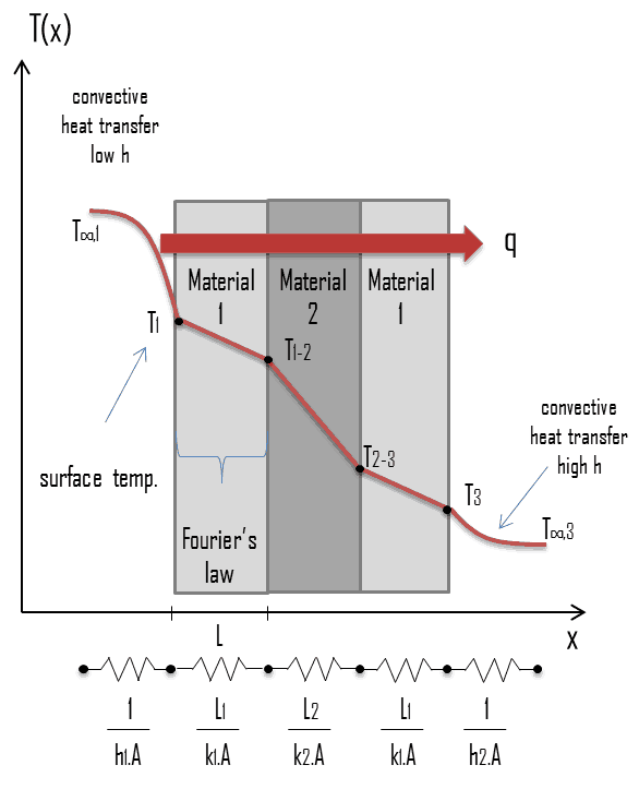
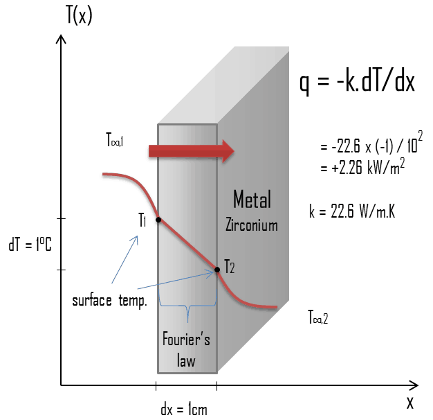
Thermal conduction - thermal conductivity - zirconiumThermal conduction, also called heat conduction, occurs within a body or between two bodies in contact without the involvement of mass flow and mixing. It is the direct microscopic exchange of kinetic energy of particles through the boundary between two systems. Heat transfer by conduction is dependent upon the driving “force” of temperature difference and the thermal conductivity (or the resistance to heat transfer). The thermal conductivity is dependent upon the nature and dimensions of the heat transfer medium. All heat transfer problems involve the temperature difference, the geometry, and the physical properties of the object being studied. In conduction heat transfer problems, the object being studied is usually a solid.

Microscopically this mode of energy transfer is attributed to free electron flow from higher to lower energy levels, lattice vibration and molecular collision. Consider a block of stone at high temperature, that consists of atoms that are oscillating intensely around their average positions. At low temperatures, the atoms continue to oscillate, but with less intensity. zeroth-law-of-thermodynamics-heatIf a hotter block of stone is put in contact with a cooler block, the intensely oscillating atoms at the edge of the hotter block gives off its kinetic energy to the less oscillating atoms at the edge of the cool block. In this case there is energy transfer between these two blocks and heat flows from the hotter to the cooler block by this random vibrations. The modern view is to ascribe the energy transfer to lattice waves induced by atomic motion. In an electrical insulators, the energy transfer is exclusively via these lattice waves. In a conductor, it is also due to the translational motion of the free electrons.

See also: Zeroth Law of Thermodynamics

In general, metals are usually good conductors of thermal energy. It is closely associated with its good electrical conductivity. For metals, the thermal conductivity is quite high, and those metals which are the best electrical conductors are also the best thermal conductors. This is due to the way that metals bond chemically. Metallic bonds have free-moving electrons (free electrons) that transfer thermal energy rapidly through the metal. The electron fluid of a conductive metallic solid conducts most of the heat flux through the solid. Phonon flux is still present, but carries less of the energy. These mechanisms of thermal conduction will be discussed later.

Fourier’s law of Thermal Conduction

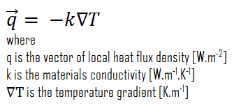
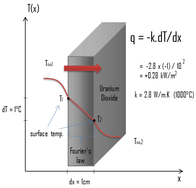
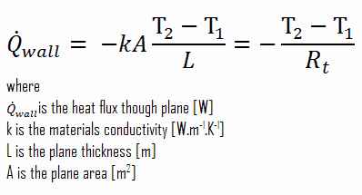
Heat transfer processes can be quantified in terms of appropriate rate equations. The rate equation in this heat transfer mode is based on Fourier’s law of thermal conduction. This law states that the time rate of heat transfer through a material is proportional to the negative gradient in the temperature and to the area, at right angles to that gradient, through which the heat flows. Its differential form is:

Fourier’s law of Thermal Conduction

 
Heat Flux
The rate of heat transfer per unit area normal to the direction of heat transfer is called heat flux. Sometimes it is also referred to as heat flux density. In SI its units are watts per square metre (W.m−2). It has both a direction and a magnitude, and so it is a vector quantity. The average heat flux is expressed as:

heat flux density - equation

where A is the heat transfer area. The unit of heat flux in English units is Btu/h·ft2. Note that heat flux may vary with time as well as position on a surface.

In nuclear reactors, limitations of the local heat flux is of the highest importance for reactor safety. Since nuclear fuel consist of fuel rods, the heat flux is there defined in units of W/cm (local linear heat flux) or kW/rod (power per fuel rod).

The proportionality constant obtained in the relation is known as thermal conductivity, k (or λ), of the material. A material that readily transfers energy by conduction is a good thermal conductor and has a high value of k. Fourier’s law is an expression that define the thermal conductivity.

As can be seen, to solve the Fourier’s law we have to involve the temperature difference, the geometry, and the thermal conductivity of the object. This law was first formulated by Joseph Fourier in 1822 who concluded that “the heat flux resulting from thermal conduction is proportional to the magnitude of the temperature gradient and opposite to it in sign”.

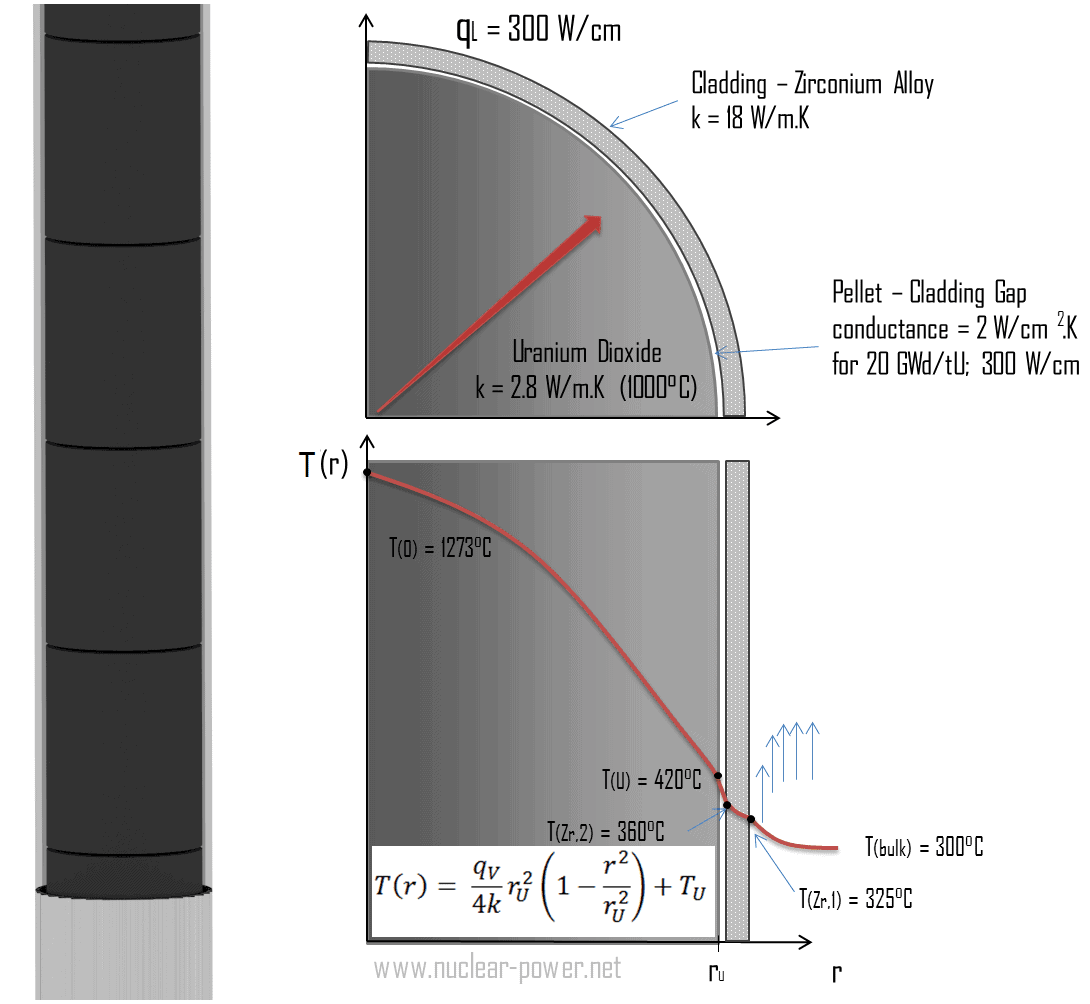
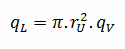
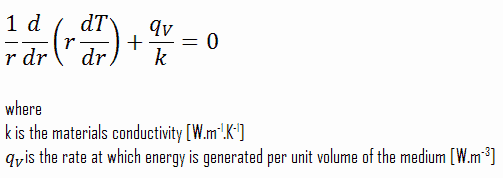
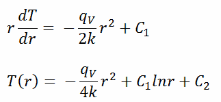
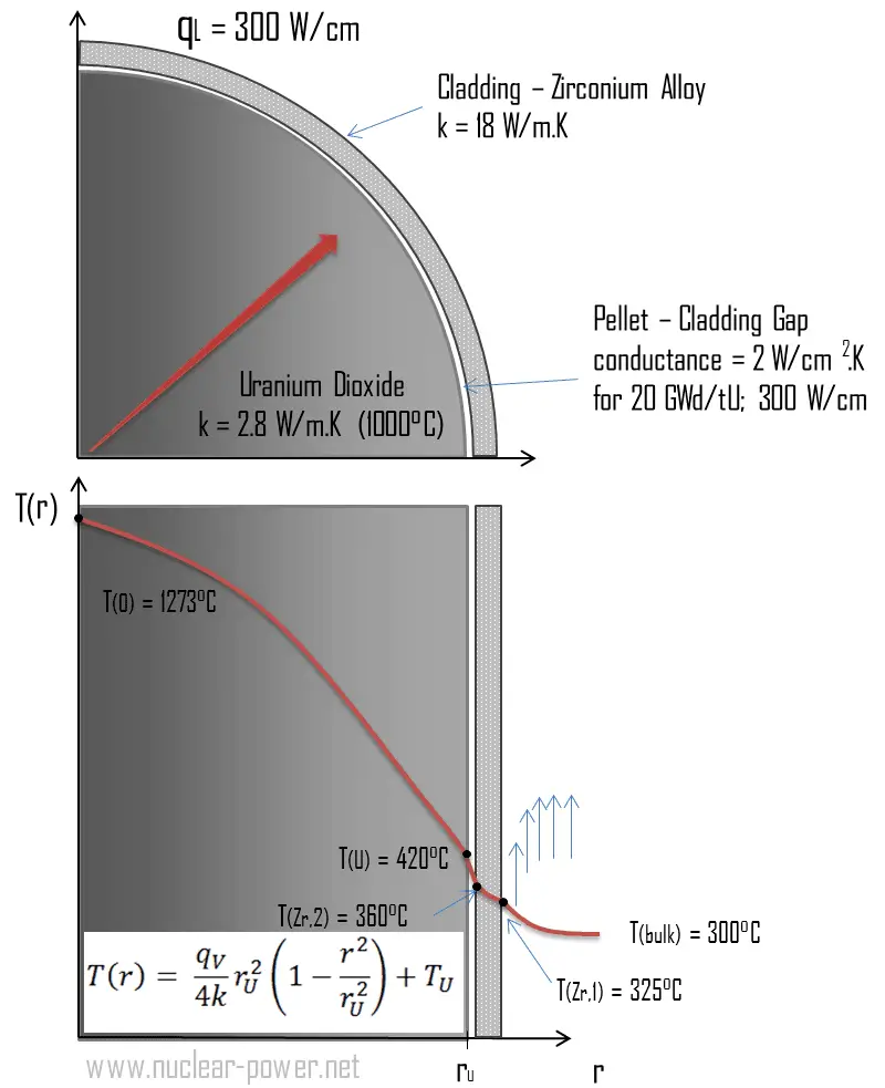
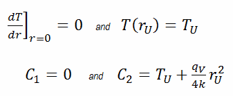
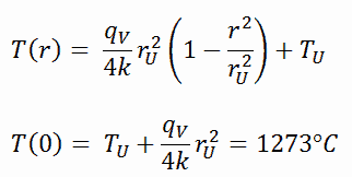
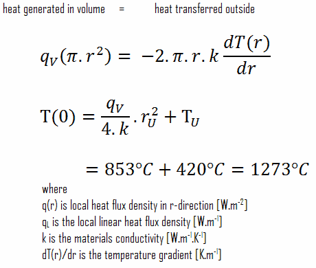
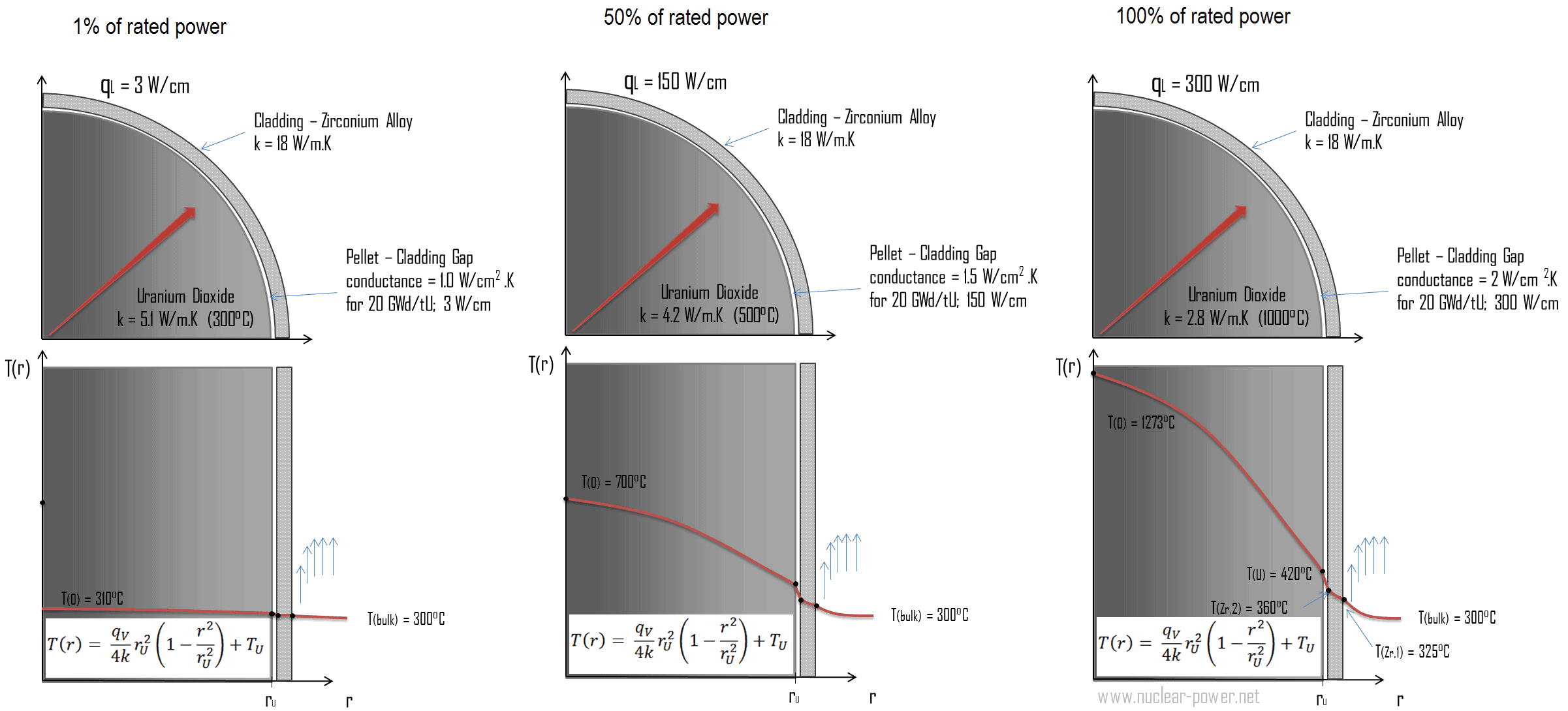
Similarly as the Fourier’s law determines the heat flux through a slab, it can also be used to determine the temperature difference, when q is known. This can be used for calculation of the temperature in the centre of fuel pellet as will be shown in following sections.

 
Thermal Conductivity
The heat transfer characteristics of a solid material are measured by a property called the thermal conductivity, k (or λ), measured in W/m.K. It is a measure of a substance’s ability to transfer heat through a material by conduction. Note that Fourier’s law applies for all matter, regardless of its state (solid, liquid, or gas), therefore, it is also defined for liquids and gases.

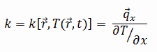
The thermal conductivity of most liquids and solids varies with temperature. For vapors, it also depends upon pressure. In general:

thermal conductivity - definition

Most materials are very nearly homogeneous, therefore we can usually write k = k (T). Similar definitions are associated with thermal conductivities in the y- and z-directions (ky, kz), but for an isotropic material the thermal conductivity is independent of the direction of transfer, kx = ky = kz = k.

From the foregoing equation, it follows that the conduction heat flux increases with increasing thermal conductivity and increases with increasing temperature difference. In general, the thermal conductivity of a solid is larger than that of a liquid, which is larger than that of a gas. This trend is due largely to differences in intermolecular spacing for the two states of matter. In particular, diamond has the highest hardness and thermal conductivity of any bulk material.

See also: Thermal Conductivity

Thermal Conductivity of Uranium Dioxide
Thermal conduction - thermal conductivity - uranium dioxideMost of PWRs use the uranium fuel, which is in the form of uranium dioxide. Uranium dioxide is a black semiconducting solid with very low thermal conductivity. On the other hand the uranium dioxide has very high melting point and has well known behavior. The UO2 is pressed into pellets, these pellets are then sintered into the solid.

These pellets are then loaded and encapsulated within a fuel rod (or fuel pin), which is made of zirconium alloys due to its very low absorption cross-section (unlike the stainless steel). The surface of the tube, which covers the pellets, is called fuel cladding. Fuel rods are base element of a fuel assembly.

The thermal conductivity of uranium dioxide is very low when compared with metal uranium, uranium nitride, uranium carbide and zirconium cladding material. The thermal conductivity is one of parameters, which determine the fuel centerline temperature. This low thermal conductivity can result in localised overheating in the fuel centerline and therefore this overheating must be avoided.  Overheating of the fuel is prevented by maintaining the steady state peak linear heat rate (LHR) or the Heat Flux Hot Channel Factor – FQ(z) below the level at which fuel centerline melting occurs. Expansion of the fuel pellet upon centerline melting may cause the pellet to stress the cladding to the point of failure.

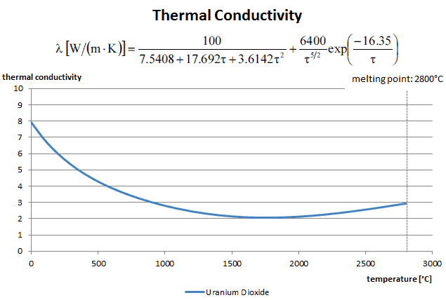
Thermal conductivity of solid UO2 with a density of 95% is estimated by following correlation [Klimenko; Zorin]:

thermal conductivity of uranium - equation

where τ = T/1000. The uncertainty of this correlation is +10% in the range from 298.15 to 2000 K and +20% in the range from 2000 to 3120 K.

Thermal Conductivity - Uranium Dioxide - chart

Special reference: Thermal and Nuclear Power Plants/Handbook ed. by A.V. Klimenko and V.M. Zorin. MEI Press, 2003.

Special reference: Thermophysical Properties of Materials For Nuclear Engineering: A Tutorial and Collection of Data. IAEA-THPH, IAEA, Vienna, 2008. ISBN 978–92–0–106508–7.

Thermal Resistance
thermal resistance - definition - analogyIn engineering, another very important concept is often used. Since there is an analogy between the diffusion of heat and electrical charge, engineers often use the thermal resistance (i.e. thermal resistance against heat conduction) to calculate heat transfer through materials. Thermal resistance is the reciprocal of thermal conductance. Just as an electrical resistance is associated with the conduction of electricity, a thermal resistance may be associated with the conduction of heat.

Consider a plane wall of thickness L and average thermal conductivity k. The two surfaces of the wall are maintained at constant temperatures of T1 and T2. For one-dimensional steady heat conduction through the wall, we have T(x). Then Fourier’s law of heat conduction for the wall can be expressed as:

Fourier’s law with thermal resistance

Heat Conduction Equation

Nuclear Fuel - TemperaturesIn previous sections, we have dealt especially with one-dimensional steady-state heat transfer, which can be characterized by the Fourier’s law of heat conduction. But its applicability is very limited. This law assumes steady-state heat transfer through a planar body (note that, Fourier’s law can be derived also for cylindrical and spherical coordinates), without heat sources. It is simply the rate equation in this heat transfer mode, where the temperature gradient is known.

But a major problem in most conduction analyses is to determine the temperature field in a medium resulting from conditions imposed on its boundaries. In engineering, we have to solve heat transfer problems involving different geometries and different conditions such as a cylindrical nuclear fuel element, which involves internal heat source or the wall of a spherical containment. These problems are more complex than the planar analyses we did in previous sections. Therefore these problems will be the subject of this section, in which the heat conduction equation will be introduced and solved.

See also: Heat Equation

Heat Conduction Equation – General Form

The heat conduction equation is a partial differential equation that describes the distribution of heat (or the temperature field) in a given body over time. Detailed knowledge of the temperature field is very important in thermal conduction through materials. Once this temperature distribution is known, the conduction heat flux at any point in the material or on its surface may be computed from Fourier’s law.

The heat equation is derived from Fourier’s law and conservation of energy. The Fourier’s law states that the time rate of heat transfer through a material is proportional to the negative gradient in the temperature and to the area, at right angles to that gradient, through which the heat flows.

Fourier’s law of Thermal Conduction

A change in internal energy per unit volume in the material, ΔQ, is proportional to the change in temperature, Δu. That is:

∆Q = ρ.cp.∆T

General Form

Using these two equation we can derive the general heat conduction equation:

Heat Conduction Equation - Fourier-Biot equation

This equation is also known as the Fourier-Biot equation, and provides the basic tool for heat conduction analysis. From its solution, we can obtain the temperature field as a function of time.

In words, the heat conduction equation states that:

At any point in the medium the net rate of energy transfer by conduction into a unit volume plus the volumetric rate of thermal energy generation must equal the rate of change of thermal energy stored within the volume.

See also: Thermal Diffusivity

Example – Thermal Conduction in Fuel Rod

Nuclear Fuel - TemperaturesMost of PWRs use the uranium fuel, which is in the form of uranium dioxide. Uranium dioxide is a black semiconducting solid with very low thermal conductivity. On the other hand the uranium dioxide has very high melting point and has well known behavior. The UO2 is pressed into cylindrical pellets, these pellets are then sintered into the solid.

These cylindrical pellets are then loaded and encapsulated within a fuel rod (or fuel pin), which is made of zirconium alloys due to its very low absorption cross-section (unlike the stainless steel). The surface of the tube, which covers the pellets, is called fuel cladding.

See also: Thermal Conduction of Uranium Dioxide

Thermal and mechanical behavior of fuel pellets and fuel rods constitute one of three key core design disciplines. Nuclear fuel is operated under very inhospitable conditions (thermal, radiation, mechanical) and must withstand more than normal conditions operation. For example temperatures in the centre of fuel pellets reach more than 1000°C (1832°F) accompanied by fission-gas releases. Therefore detailed knowledge of temperature distribution within a single fuel rod is essential for safe operation of nuclear fuel. In this section we will study heat conduction equation in cylindrical coordinates using Dirichlet boundary condition with given surface temperature (i.e. using Dirichlet boundary condition). Comprehensive analysis of fuel rod temperature profile will be studied in separate section.

Temperature in the centerline of a fuel pellet

Consider the fuel pellet of radius rU = 0.40 cm, in which there is uniform and constant heat generation per unit volume, qV [W/m3]. Instead of volumetric heat rate qV [W/m3], engineers often use the linear heat rate, qL [W/m], which represents the heat rate of one meter of fuel rod. The linear heat rate can be calculated from the volumetric heat rate by:

linear heat rate vs volumetric heat rate

The centreline is taken as the origin for r-coordinate. Due to symmetry in z-direction and in azimuthal direction, we can separate of variables and simplify this problem to one-dimensional problem. Thus, we will solve for the temperature as function of radius, T(r), only. For constant thermal conductivity, k, the appropriate form of the cylindrical heat equation, is:

heat equation - cylindrical - 2

The general solution of this equation is:

heat equation - cylindrical - general solution

where C1 and C2 are the constants of integration.

Thermal conduction - fuel pelletCalculate the temperature distribution, T(r), in this fuel pellet, if:

  • the temperatures at the surface of the fuel pellet is TU = 420°C
  • the fuel pellet radius rU = 4 mm.
  • the averaged material’s conductivity is k = 2.8 W/m.K (corresponds to uranium dioxide at 1000°C)
  • the linear heat rate is qL = 300 W/cm and thus the volumetric heat rate is qV = 597 x 106 W/m3

In this case, the surface is maintained at given temperatures TU. This corresponds to the Dirichlet boundary condition. Moreover, this problem is thermally symmetric and therefore we may use also thermal symmetry boundary condition. The constants may be evaluated using substitution into the general solution and are of the form:

heat equation - cylindrical - boundary conditions

The resulting temperature distribution and the centerline (r = 0) temperature (maximum) in this cylindrical fuel pellet at these specific boundary conditions will be:

heat equation - cylindrical - solution

The radial heat flux at any radius, qr [W.m-1], in the cylinder may, of course, be determined by using the temperature distribution and with the Fourier’s law. Note that, with heat generation the heat flux is no longer independent of r.

∆T in fuel pellet

Detailed knowledge of geometry, outer radius of fuel pellet, volumetric heat rate, and the pellet surface temperature (TU) determines ∆T between outer surface and centerline of fuel pellet. Therefore we can calculate the centerline temperature (TZr,2) simply using the energy conservation between heat generated in the volume and the transferred outside the volume:

dT in fuel pellet - equation

The following figure shows the temperature distribution in the fuel pellet at various power levels.

Temperature distribution - nuclear fuel

______

The temperature in an operating reactor varies from point to point within the system. As a consequence, there is always one fuel rod and one local volume, that are hotter than all the rest. In order to limit these hot places the peak power limits must be introduced. The peak power limits are associated with a boiling crisis and with the conditions which could cause fuel pellet melt. However, metallurgical considerations place an upper limits on the temperature of the fuel cladding and the fuel pellet. Above these temperatures there is a danger that the fuel may be damaged. One of the major objectives in the design of a nuclear reactors is to provide for the removal of the heat produced at the desired power level, while assuring that the maximum fuel temperature and the maximum cladding temperature are always below these predetermined values.

 
References:
Heat Transfer:
  1. Fundamentals of Heat and Mass Transfer, 7th Edition. Theodore L. Bergman, Adrienne S. Lavine, Frank P. Incropera. John Wiley & Sons, Incorporated, 2011. ISBN: 9781118137253.
  2. Heat and Mass Transfer. Yunus A. Cengel. McGraw-Hill Education, 2011. ISBN: 9780071077866.
  3. Fundamentals of Heat and Mass Transfer. C. P. Kothandaraman. New Age International, 2006, ISBN: 9788122417722.
  4. U.S. Department of Energy, Thermodynamics, Heat Transfer and Fluid Flow. DOE Fundamentals Handbook, Volume 2 of 3. May 2016.

Nuclear and Reactor Physics:

  1. J. R. Lamarsh, Introduction to Nuclear Reactor Theory, 2nd ed., Addison-Wesley, Reading, MA (1983).
  2. J. R. Lamarsh, A. J. Baratta, Introduction to Nuclear Engineering, 3d ed., Prentice-Hall, 2001, ISBN: 0-201-82498-1.
  3. W. M. Stacey, Nuclear Reactor Physics, John Wiley & Sons, 2001, ISBN: 0- 471-39127-1.
  4. Glasstone, Sesonske. Nuclear Reactor Engineering: Reactor Systems Engineering, Springer; 4th edition, 1994, ISBN: 978-0412985317
  5. W.S.C. Williams. Nuclear and Particle Physics. Clarendon Press; 1 edition, 1991, ISBN: 978-0198520467
  6. G.R.Keepin. Physics of Nuclear Kinetics. Addison-Wesley Pub. Co; 1st edition, 1965
  7. Robert Reed Burn, Introduction to Nuclear Reactor Operation, 1988.
  8. U.S. Department of Energy, Nuclear Physics and Reactor Theory. DOE Fundamentals Handbook, Volume 1 and 2. January 1993.
  9. Paul Reuss, Neutron Physics. EDP Sciences, 2008. ISBN: 978-2759800414.

Advanced Reactor Physics:

  1. K. O. Ott, W. A. Bezella, Introductory Nuclear Reactor Statics, American Nuclear Society, Revised edition (1989), 1989, ISBN: 0-894-48033-2.
  2. K. O. Ott, R. J. Neuhold, Introductory Nuclear Reactor Dynamics, American Nuclear Society, 1985, ISBN: 0-894-48029-4.
  3. D. L. Hetrick, Dynamics of Nuclear Reactors, American Nuclear Society, 1993, ISBN: 0-894-48453-2.
  4. E. E. Lewis, W. F. Miller, Computational Methods of Neutron Transport, American Nuclear Society, 1993, ISBN: 0-894-48452-4.

See also:

Heat Transfer

We hope, this article, Thermal Conduction – Heat Conduction, helps you. If so, give us a like in the sidebar. Main purpose of this website is to help the public to learn some interesting and important information about thermal engineering.