Facebook Instagram Youtube Twitter

What is Thermal Conductivity – Definition

Thermal conductivity is a measure of a substance’s ability to transfer heat through a material by conduction. Thermal conductivity, k (or λ), measured in W/m.K. Thermal Engineering

Thermal Conductivity
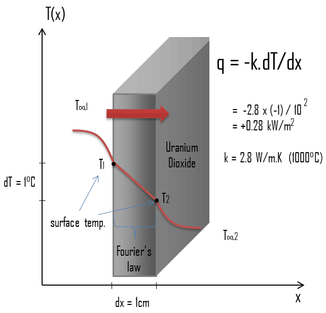
Thermal conduction - thermal conductivity - uranium dioxideThe heat transfer characteristics of a solid material are measured by a property called the thermal conductivity, k (or λ), measured in W/m.K. It is a measure of a substance’s ability to transfer heat through a material by conduction. Note that Fourier’s law applies for all matter, regardless of its state (solid, liquid, or gas), therefore, it is also defined for liquids and gases.

The thermal conductivity of most liquids and solids varies with temperature. For vapors, it also depends upon pressure. In general:
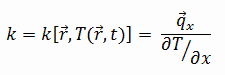
thermal conductivity - definition

Most materials are very nearly homogeneous, therefore we can usually write k = k (T). Similar definitions are associated with thermal conductivities in the y- and z-directions (ky, kz), but for an isotropic material the thermal conductivity is independent of the direction of transfer, kx = ky = kz = k.

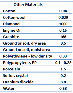
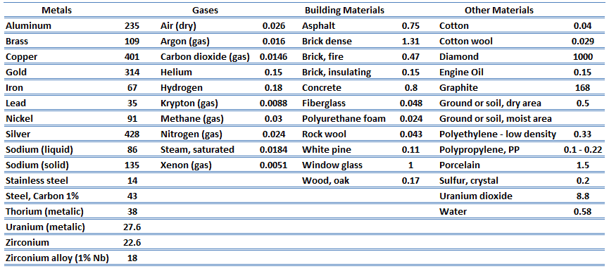
From the foregoing equation, it follows that the conduction heat flux increases with increasing thermal conductivity and increases with increasing temperature difference. In general, the thermal conductivity of a solid is larger than that of a liquid, which is larger than that of a gas. This trend is due largely to differences in intermolecular spacing for the two states of matter. In particular, diamond has the highest hardness and thermal conductivity of any bulk material.
thermal conductivity - materials

 
Fourier’s law of Thermal Conduction
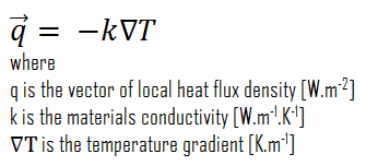
Heat transfer processes can be quantified in terms of appropriate rate equations. The rate equation in this heat transfer mode is based on Fourier’s law of thermal conduction. This law states that the time rate of heat transfer through a material is proportional to the negative gradient in the temperature and to the area, at right angles to that gradient, through which the heat flows. Its differential form is:

Fourier’s law of Thermal Conduction

The proportionality constant obtained in the relation is known as thermal conductivity, k (or λ), of the material. A material that readily transfers energy by conduction is a good thermal conductor and has a high value of k. Fourier’s law is an expression that define the thermal conductivity.

As can be seen, to solve the Fourier’s law we have to involve the temperature difference, the geometry, and the thermal conductivity of the object. This law was first formulated by Joseph Fourier in 1822 who concluded that “the heat flux resulting from thermal conduction is proportional to the magnitude of the temperature gradient and opposite to it in sign”.

Similarly as the Fourier’s law determines the heat flux through a slab, it can also be used to determine the temperature difference, when q is known. This can be used for calculation of the temperature in the centre of fuel pellet as will be shown in following sections.
Units of Thermal Conductivity
In SI units, thermal conductivity is measured in watts per meter-kelvin – W/(m·K). In Imperial units, thermal conductivity is measured in BTU/(hr·ft⋅°F).

Note that, British Thermal Unit (unit: BTU) is defined to be the amount of heat that must be absorbed by a 1 one pound of water to raise its temperature by 1 °F at the temperature that water has its greatest density (approximately 39 degrees Fahrenheit).

Other units which are closely related to the thermal conductivity are in common use in the construction and textile industries. The construction industry makes use of units such as the R-value (resistance), which is expressed as the thickness of the material normalized to the thermal conductivity, and under uniform conditions it is the ratio of the temperature difference across an insulator and the heat flux density through it: R(x) = ∆T/q. The higher the R-value, the more a material prevents heat transfer. As can be seen, the resistance is dependent on the thickness of the product.

Thermal Conductivity of Chemical Elements
thermal conductivity

Thermal Conductivity of Fluids (Liquids and Gases)

In physics, a fluid is a substance that continually deforms (flows) under an applied shear stress. Fluids are a subset of the phases of matter and include liquids, gases, plasmas and, to some extent, plastic solids. Because the intermolecular spacing is much larger and the motion of the molecules is more random for the fluid state than for the solid state, thermal energy transport is less effective. The thermal conductivity of gases and liquids is therefore generally smaller than that of solids. In liquids, the thermal conduction is caused by atomic or molecular diffusion. In gases, the thermal conduction is caused by diffusion of molecules from higher energy level to the lower level.

Thermal Conductivity of Gases
thermal conductivity - gasesThe effect of temperature, pressure, and chemical species on the thermal conductivity of a gas may be explained in terms of the kinetic theory of gases. Air and other gases are generally good insulators, in the absence of convection. Therefore, many insulating materials (e.g.polystyrene) function simply by having a large number of gas-filled pockets which prevent large-scale convection. Alternation of gas pocket and solid material causes that the heat must be transferred through many interfaces causing rapid decrease in heat transfer coefficient.

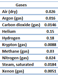
The thermal conductivity of gases is directly proportional to the density of the gas, the mean molecular speed, and especially to the mean free path of molecule. The mean free path also depends on the diameter of the molecule, with larger molecules more likely to experience collisions than small molecules, which is the average distance traveled by an energy carrier (a molecule) before experiencing a collision. Light gases, such as hydrogen and helium typically have high thermal conductivity. Dense gases such as xenon and dichlorodifluoromethane have low thermal conductivity.

In general, the thermal conductivity of gases increases with increasing temperature.

Thermal Conductivity of Liquids

As was written, in liquids, the thermal conduction is caused by atomic or molecular diffusion, but physical mechanisms for explaining the thermal conductivity of liquids are not well understood. Liquids tend to have better thermal conductivity than gases, and the ability to flow makes a liquid suitable for removing excess heat from mechanical components. The heat can be removed by channeling the liquid through a heat exchanger. The coolants used in nuclear reactors include water or liquid metals, such as sodium or lead.

The thermal conductivity of nonmetallic liquids generally decreases with increasing temperature.
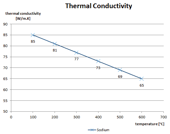
 
Thermal Conductivity of Sodium
Liquid sodium is used as a heat transfer fluid in some types of nuclear reactors because it has the high thermal conductivity and low neutron absorption cross section required to achieve a high neutron flux in the reactor. The high thermal conductivity properties effectively create a reservoir of heat capacity which provides thermal inertia against overheating.

thermal conductivity - sodium

Special reference: Thermophysical Properties of Materials For Nuclear Engineering: A Tutorial and Collection of Data. IAEA-THPH, IAEA, Vienna, 2008. ISBN 978–92–0–106508–7.

Thermal Conductivity of Water and Steam
Water and steam are a common fluid used for heat exchange in the primary circuit (from surface of fuel rods to the coolant flow) and in the secondary circuit. It used due to its availability and high heat capacity, both for cooling and heating. It is especially effective to transport heat through vaporization and condensation of water because of its very large latent heat of vaporization.

A disadvantage is that water moderated reactors have to use high pressure primary circuit in order to keep water in liquid state and in order to achieve sufficient thermodynamic efficiency. Water and steam also reacts with metals commonly found in industries such as steel and copper that are oxidized faster by untreated water and steam. In almost all thermal power stations (coal, gas, nuclear), water is used as the working fluid (used in a closed loop between boiler, steam turbine and condenser), and the coolant (used to exchange the waste heat to a water body or carry it away by evaporation in a cooling tower).

Thermal Conductivity of Water
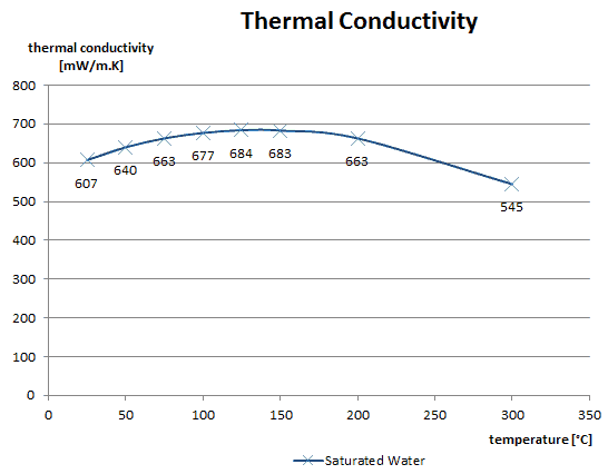
thermal conductivity - saturated water

Thermal Conductivity of Steam

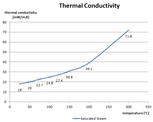
thermal conductivity - saturated steam

See also: Steam Tables

Special reference: Thermophysical Properties of Materials For Nuclear Engineering: A Tutorial and Collection of Data. IAEA-THPH, IAEA, Vienna, 2008. ISBN 978–92–0–106508–7.

Thermal Conductivity of Helium
Helium is a chemical element with atomic number 2 which means there are 2 protons and 2 electrons in the atomic structure. The chemical symbol for Helium is He.

It is a colorless, odorless, tasteless, non-toxic, inert, monatomic gas, the first in the noble gas group in the periodic table. Its boiling point is the lowest among all the elements.

Because of helium’s relatively low molar (atomic) mass, its thermal conductivity, specific heat, and sound speed in the gas phase are all greater than any other gas except hydrogen. For its inertness and high thermal conductivity, neutron transparency, and because it does not form radioactive isotopes under reactor conditions, helium is used as a heat-transfer medium in some gas-cooled nuclear reactors (e.g. High-temperature Gas-cooled Reactors – HTGR).
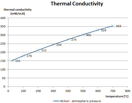
thermal conductivity - helium

Special reference: Thermophysical Properties of Materials For Nuclear Engineering: A Tutorial and Collection of Data. IAEA-THPH, IAEA, Vienna, 2008. ISBN 978–92–0–106508–7.

Thermal Conductivity of Solids

Transport of thermal energy in solids may be generally due to two effects:

  • the migration of free electrons
  • lattice vibrational waves (phonons)

When electrons and phonons carry thermal energy leading to conduction heat transfer in a solid, the thermal conductivity may be expressed as:

k = ke + kph

Thermal Conductivity of Metals
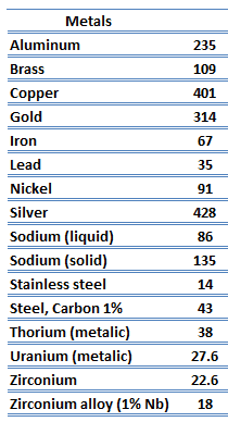
thermal conductivity - metalsMetals are solids and as such they possess crystalline structure where the ions (nuclei with their surrounding shells of core electrons) occupy translationally equivalent positions in the crystal lattice. Metals in general have high electrical conductivity, high thermal conductivity, and high density. Accordingly, transport of thermal energy may be due to two effects:

  • the migration of free electrons
  • lattice vibrational waves (phonons).

When electrons and phonons carry thermal energy leading to conduction heat transfer in a solid, the thermal conductivity may be expressed as:

k = ke + kph

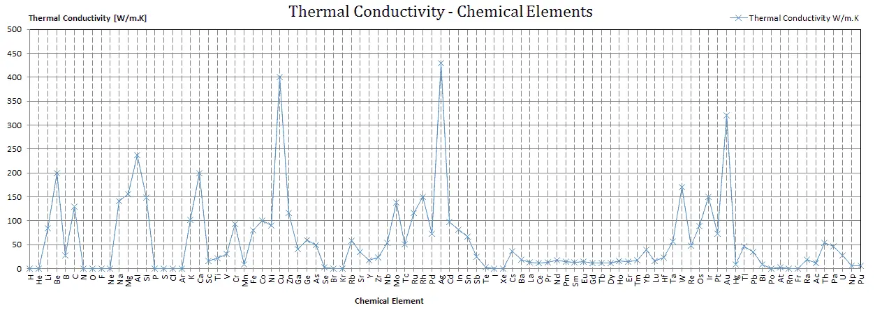
The unique feature of metals as far as their structure is concerned is the presence of charge carriers, specifically electrons. The electrical and thermal conductivities of metals originate from the fact that their outer electrons are delocalized. Their contribution to the thermal conductivity is referred to as the electronic thermal conductivity, ke. In fact, in pure metals such as gold, silver, copper, and aluminum, the heat current associated with the flow of electrons by far exceeds a small contribution due to the flow of phonons. In contrast, for alloys, the contribution of kph to k is no longer negligible.
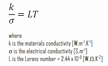
 
Wiedemann-Franz Law - Lorenz Number
At a given temperature, the thermal and electrical conductivities of metals are proportional, but raising the temperature increases the thermal conductivity while decreasing the electrical conductivity. This behavior is quantified in the Wiedemann–Franz law. This law states that the ratio of the electronic contribution of the thermal conductivity (k) to the electrical conductivity (σ) of a metal is proportional to the temperature (T).

Wiedemann-Franz Law - Lorentz Number - definition

Qualitatively, this relationship is based upon the fact that the heat and electrical transport both involve the free electrons in the metal. The electrical conductivity decreases with particle velocity increases because the collisions divert the electrons from forward transport of charge. However, the thermal conductivity increases with the average particle velocity since that increases the forward transport of energy. The Wiedemann-Franz law is generally well obeyed at high temperatures. In the low and intermediate temperature regions, however, the law fails due to the inelastic scattering of the charge carriers.

It must be noted, the general correlation between electrical and thermal conductance does not hold for other materials, due to the increased importance of phonon carriers for heat in non-metals.

Thermal Conductivity of Nonmetals
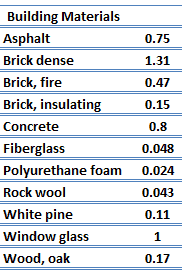
thermal conductivity - building materialsFor nonmetallic solids, k is determined primarily by kph, which increases as the frequency of interactions between the atoms and the lattice decreases. In fact, lattice thermal conduction is the dominant thermal conduction mechanism in nonmetals, if not the only one. In solids, atoms vibrate about their equilibrium positions (crystal lattice). The vibrations of atoms are not independent of each other, but are rather strongly coupled with neighboring atoms. The regularity of the lattice arrangement has an important effect on kph, with crystalline (well-ordered) materials like quartz having a higher thermal conductivity than amorphous materials like glass. At sufficiently high temperatures kph ∝ 1/T.

thermal conductivity - solidsThe quanta of the crystal vibrational field are referred to as ‘‘phonons.’’ A phonon is a collective excitation in a periodic, elastic arrangement of atoms or molecules in condensed matter, like solids and some liquids. Phonons play a major role in many of the physical properties of condensed matter, like thermal conductivity and electrical conductivity. In fact, for crystalline, nonmetallic solids such as diamond, kph can be quite large, exceeding values of k associated with good conductors, such as aluminum. In particular, diamond has the highest hardness and thermal conductivity (k = 1000 W/m.K) of any bulk material.

Thermal Conductivity of Uranium Dioxide

Thermal conduction - thermal conductivity - uranium dioxideMost of PWRs use the uranium fuel, which is in the form of uranium dioxide. Uranium dioxide is a black semiconducting solid with very low thermal conductivity. On the other hand the uranium dioxide has very high melting point and has well known behavior. The UO2 is pressed into pellets, these pellets are then sintered into the solid.

These pellets are then loaded and encapsulated within a fuel rod (or fuel pin), which is made of zirconium alloys due to its very low absorption cross-section (unlike the stainless steel). The surface of the tube, which covers the pellets, is called fuel cladding. Fuel rods are base element of a fuel assembly.

The thermal conductivity of uranium dioxide is very low when compared with metal uranium, uranium nitride, uranium carbide and zirconium cladding material. The thermal conductivity is one of parameters, which determine the fuel centerline temperature. This low thermal conductivity can result in localised overheating in the fuel centerline and therefore this overheating must be avoided.  Overheating of the fuel is prevented by maintaining the steady state peak linear heat rate (LHR) or the Heat Flux Hot Channel Factor – FQ(z) below the level at which fuel centerline melting occurs. Expansion of the fuel pellet upon centerline melting may cause the pellet to stress the cladding to the point of failure.

Thermal conductivity of solid UO2 with a density of 95% is estimated by following correlation [Klimenko; Zorin]:

thermal conductivity of uranium - equation

where τ = T/1000. The uncertainty of this correlation is +10% in the range from 298.15 to 2000 K and +20% in the range from 2000 to 3120 K.
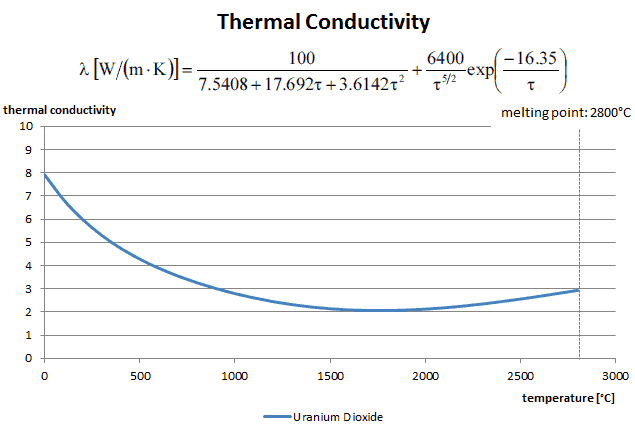
Thermal Conductivity - Uranium Dioxide - chart

Special reference: Thermal and Nuclear Power Plants/Handbook ed. by A.V. Klimenko and V.M. Zorin. MEI Press, 2003.

Special reference: Thermophysical Properties of Materials For Nuclear Engineering: A Tutorial and Collection of Data. IAEA-THPH, IAEA, Vienna, 2008. ISBN 978–92–0–106508–7.

Thermal Conductivity of Zirconium
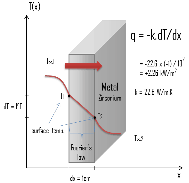
Thermal conduction - thermal conductivity - zirconiumZirconium is a lustrous, grey-white, strong transition metal that resembles hafnium and, to a lesser extent, titanium. Zirconium is mainly used as a refractory and opacifier, although small amounts are used as an alloying agent for its strong resistance to corrosion. Zirconium alloy (e.g. Zr + 1%Nb) is widely used as a cladding for nuclear reactor fuels. The desired properties of these alloys are a low neutron-capture cross-section and resistance to corrosion under normal service conditions. Zirconium alloys have lower thermal conductivity (about 18 W/m.K) than pure zirconium metal (about 22 W/m.K).

Special reference: Thermophysical Properties of Materials For Nuclear Engineering: A Tutorial and Collection of Data. IAEA-THPH, IAEA, Vienna, 2008. ISBN 978–92–0–106508–7.

 
References:
Heat Transfer:
  1. Fundamentals of Heat and Mass Transfer, 7th Edition. Theodore L. Bergman, Adrienne S. Lavine, Frank P. Incropera. John Wiley & Sons, Incorporated, 2011. ISBN: 9781118137253.
  2. Heat and Mass Transfer. Yunus A. Cengel. McGraw-Hill Education, 2011. ISBN: 9780071077866.
  3. Fundamentals of Heat and Mass Transfer. C. P. Kothandaraman. New Age International, 2006, ISBN: 9788122417722.
  4. U.S. Department of Energy, Thermodynamics, Heat Transfer and Fluid Flow. DOE Fundamentals Handbook, Volume 2 of 3. May 2016.

Nuclear and Reactor Physics:

  1. J. R. Lamarsh, Introduction to Nuclear Reactor Theory, 2nd ed., Addison-Wesley, Reading, MA (1983).
  2. J. R. Lamarsh, A. J. Baratta, Introduction to Nuclear Engineering, 3d ed., Prentice-Hall, 2001, ISBN: 0-201-82498-1.
  3. W. M. Stacey, Nuclear Reactor Physics, John Wiley & Sons, 2001, ISBN: 0- 471-39127-1.
  4. Glasstone, Sesonske. Nuclear Reactor Engineering: Reactor Systems Engineering, Springer; 4th edition, 1994, ISBN: 978-0412985317
  5. W.S.C. Williams. Nuclear and Particle Physics. Clarendon Press; 1 edition, 1991, ISBN: 978-0198520467
  6. G.R.Keepin. Physics of Nuclear Kinetics. Addison-Wesley Pub. Co; 1st edition, 1965
  7. Robert Reed Burn, Introduction to Nuclear Reactor Operation, 1988.
  8. U.S. Department of Energy, Nuclear Physics and Reactor Theory. DOE Fundamentals Handbook, Volume 1 and 2. January 1993.
  9. Paul Reuss, Neutron Physics. EDP Sciences, 2008. ISBN: 978-2759800414.

Advanced Reactor Physics:

  1. K. O. Ott, W. A. Bezella, Introductory Nuclear Reactor Statics, American Nuclear Society, Revised edition (1989), 1989, ISBN: 0-894-48033-2.
  2. K. O. Ott, R. J. Neuhold, Introductory Nuclear Reactor Dynamics, American Nuclear Society, 1985, ISBN: 0-894-48029-4.
  3. D. L. Hetrick, Dynamics of Nuclear Reactors, American Nuclear Society, 1993, ISBN: 0-894-48453-2.
  4. E. E. Lewis, W. F. Miller, Computational Methods of Neutron Transport, American Nuclear Society, 1993, ISBN: 0-894-48452-4.

See also:

Thermal Conduction

We hope, this article, Thermal Conductivity, helps you. If so, give us a like in the sidebar. Main purpose of this website is to help the public to learn some interesting and important information about thermal engineering.
What is Thermal Conductivity – Definition – Definition

What is Thermal Conductivity – Definition. Thermal conductivity is key thermal characteristics of a solid material. It is a measure of a substance’s ability to transfer heat through a material by conduction. Thermal Engineering

What is Thermal Conductivity – Definition

Thermal conduction - thermal conductivity - uranium dioxideThe heat transfer characteristics of a solid material are measured by a property called the thermal conductivity, k (or λ), measured in W/m.K. It is a measure of a substance’s ability to transfer heat through a material by conduction. Note that Fourier’s law applies for all matter, regardless of its state (solid, liquid, or gas), therefore, it is also defined for liquids and gases.

The thermal conductivity of most liquids and solids varies with temperature. For vapors, it also depends upon pressure.

What is Thermal Conductivity – Definition

thermal conductivity - definition

Most materials are very nearly homogeneous, therefore we can usually write k = k (T). Similar definitions are associated with thermal conductivities in the y- and z-directions (ky, kz), but for an isotropic material the thermal conductivity is independent of the direction of transfer, kx = ky = kz = k.

From the foregoing equation, it follows that the conduction heat flux increases with increasing thermal conductivity and increases with increasing temperature difference. In general, the thermal conductivity of a solid is larger than that of a liquid, which is larger than that of a gas. This trend is due largely to differences in intermolecular spacing for the two states of matter. In particular, diamond has the highest hardness and thermal conductivity of any bulk material.

thermal conductivity - materials

 
References:
Heat Transfer:
  1. Fundamentals of Heat and Mass Transfer, 7th Edition. Theodore L. Bergman, Adrienne S. Lavine, Frank P. Incropera. John Wiley & Sons, Incorporated, 2011. ISBN: 9781118137253.
  2. Heat and Mass Transfer. Yunus A. Cengel. McGraw-Hill Education, 2011. ISBN: 9780071077866.
  3. Fundamentals of Heat and Mass Transfer. C. P. Kothandaraman. New Age International, 2006, ISBN: 9788122417722.
  4. U.S. Department of Energy, Thermodynamics, Heat Transfer and Fluid Flow. DOE Fundamentals Handbook, Volume 2 of 3. May 2016.

Nuclear and Reactor Physics:

  1. J. R. Lamarsh, Introduction to Nuclear Reactor Theory, 2nd ed., Addison-Wesley, Reading, MA (1983).
  2. J. R. Lamarsh, A. J. Baratta, Introduction to Nuclear Engineering, 3d ed., Prentice-Hall, 2001, ISBN: 0-201-82498-1.
  3. W. M. Stacey, Nuclear Reactor Physics, John Wiley & Sons, 2001, ISBN: 0- 471-39127-1.
  4. Glasstone, Sesonske. Nuclear Reactor Engineering: Reactor Systems Engineering, Springer; 4th edition, 1994, ISBN: 978-0412985317
  5. W.S.C. Williams. Nuclear and Particle Physics. Clarendon Press; 1 edition, 1991, ISBN: 978-0198520467
  6. G.R.Keepin. Physics of Nuclear Kinetics. Addison-Wesley Pub. Co; 1st edition, 1965
  7. Robert Reed Burn, Introduction to Nuclear Reactor Operation, 1988.
  8. U.S. Department of Energy, Nuclear Physics and Reactor Theory. DOE Fundamentals Handbook, Volume 1 and 2. January 1993.
  9. Paul Reuss, Neutron Physics. EDP Sciences, 2008. ISBN: 978-2759800414.

Advanced Reactor Physics:

  1. K. O. Ott, W. A. Bezella, Introductory Nuclear Reactor Statics, American Nuclear Society, Revised edition (1989), 1989, ISBN: 0-894-48033-2.
  2. K. O. Ott, R. J. Neuhold, Introductory Nuclear Reactor Dynamics, American Nuclear Society, 1985, ISBN: 0-894-48029-4.
  3. D. L. Hetrick, Dynamics of Nuclear Reactors, American Nuclear Society, 1993, ISBN: 0-894-48453-2.
  4. E. E. Lewis, W. F. Miller, Computational Methods of Neutron Transport, American Nuclear Society, 1993, ISBN: 0-894-48452-4.

See also:

Thermal Conductivity

We hope, this article, Thermal Conductivity – Definition, helps you. If so, give us a like in the sidebar. Main purpose of this website is to help the public to learn some interesting and important information about thermal engineering.
What is Thermal Conductivity of Fluids – Gases and Liquids – Definition

Thermal Conductivity of Fluids. The thermal conductivity of gases and liquids is therefore generally smaller than that of solids. Thermal Engineering

Thermal Conductivity of Fluids (Liquids and Gases)

In physics, a fluid is a substance that continually deforms (flows) under an applied shear stress. Fluids are a subset of the phases of matter and include liquids, gases, plasmas and, to some extent, plastic solids. Because the intermolecular spacing is much larger and the motion of the molecules is more random for the fluid state than for the solid state, thermal energy transport is less effective. The thermal conductivity of gases and liquids is therefore generally smaller than that of solids. In liquids, the thermal conduction is caused by atomic or molecular diffusion. In gases, the thermal conduction is caused by diffusion of molecules from higher energy level to the lower level.

Thermal Conductivity of Gases

thermal conductivity - gasesThe effect of temperature, pressure, and chemical species on the thermal conductivity of a gas may be explained in terms of the kinetic theory of gases. Air and other gases are generally good insulators, in the absence of convection. Therefore, many insulating materials (e.g.polystyrene) function simply by having a large number of gas-filled pockets which prevent large-scale convection. Alternation of gas pocket and solid material causes that the heat must be transferred through many interfaces causing rapid decrease in heat transfer coefficient.

The thermal conductivity of gases is directly proportional to the density of the gas, the mean molecular speed, and especially to the mean free path of molecule. The mean free path also depends on the diameter of the molecule, with larger molecules more likely to experience collisions than small molecules, which is the average distance traveled by an energy carrier (a molecule) before experiencing a collision. Light gases, such as hydrogen and helium typically have high thermal conductivity. Dense gases such as xenon and dichlorodifluoromethane have low thermal conductivity.

In general, the thermal conductivity of gases increases with increasing temperature.

Thermal Conductivity of Liquids

As was written, in liquids, the thermal conduction is caused by atomic or molecular diffusion, but physical mechanisms for explaining the thermal conductivity of liquids are not well understood. Liquids tend to have better thermal conductivity than gases, and the ability to flow makes a liquid suitable for removing excess heat from mechanical components. The heat can be removed by channeling the liquid through a heat exchanger. The coolants used in nuclear reactors include water or liquid metals, such as sodium or lead.

The thermal conductivity of nonmetallic liquids generally decreases with increasing temperature.

 
Thermal Conductivity of Sodium
Liquid sodium is used as a heat transfer fluid in some types of nuclear reactors because it has the high thermal conductivity and low neutron absorption cross section required to achieve a high neutron flux in the reactor. The high thermal conductivity properties effectively create a reservoir of heat capacity which provides thermal inertia against overheating.

thermal conductivity - sodium

Special reference: Thermophysical Properties of Materials For Nuclear Engineering: A Tutorial and Collection of Data. IAEA-THPH, IAEA, Vienna, 2008. ISBN 978–92–0–106508–7.

Thermal Conductivity of Water and Steam
Water and steam are a common fluid used for heat exchange in the primary circuit (from surface of fuel rods to the coolant flow) and in the secondary circuit. It used due to its availability and high heat capacity, both for cooling and heating. It is especially effective to transport heat through vaporization and condensation of water because of its very large latent heat of vaporization.

A disadvantage is that water moderated reactors have to use high pressure primary circuit in order to keep water in liquid state and in order to achieve sufficient thermodynamic efficiency. Water and steam also reacts with metals commonly found in industries such as steel and copper that are oxidized faster by untreated water and steam. In almost all thermal power stations (coal, gas, nuclear), water is used as the working fluid (used in a closed loop between boiler, steam turbine and condenser), and the coolant (used to exchange the waste heat to a water body or carry it away by evaporation in a cooling tower).

Thermal Conductivity of Water

thermal conductivity - saturated water

Thermal Conductivity of Steam

thermal conductivity - saturated steam

See also: Steam Tables

Special reference: Thermophysical Properties of Materials For Nuclear Engineering: A Tutorial and Collection of Data. IAEA-THPH, IAEA, Vienna, 2008. ISBN 978–92–0–106508–7.

Thermal Conductivity of Helium
Helium is a chemical element with atomic number 2 which means there are 2 protons and 2 electrons in the atomic structure. The chemical symbol for Helium is He.

It is a colorless, odorless, tasteless, non-toxic, inert, monatomic gas, the first in the noble gas group in the periodic table. Its boiling point is the lowest among all the elements.

Because of helium’s relatively low molar (atomic) mass, its thermal conductivity, specific heat, and sound speed in the gas phase are all greater than any other gas except hydrogen. For its inertness and high thermal conductivity, neutron transparency, and because it does not form radioactive isotopes under reactor conditions, helium is used as a heat-transfer medium in some gas-cooled nuclear reactors (e.g. High-temperature Gas-cooled Reactors – HTGR).

thermal conductivity - helium

Special reference: Thermophysical Properties of Materials For Nuclear Engineering: A Tutorial and Collection of Data. IAEA-THPH, IAEA, Vienna, 2008. ISBN 978–92–0–106508–7.

 
References:
Heat Transfer:
  1. Fundamentals of Heat and Mass Transfer, 7th Edition. Theodore L. Bergman, Adrienne S. Lavine, Frank P. Incropera. John Wiley & Sons, Incorporated, 2011. ISBN: 9781118137253.
  2. Heat and Mass Transfer. Yunus A. Cengel. McGraw-Hill Education, 2011. ISBN: 9780071077866.
  3. Fundamentals of Heat and Mass Transfer. C. P. Kothandaraman. New Age International, 2006, ISBN: 9788122417722.
  4. U.S. Department of Energy, Thermodynamics, Heat Transfer and Fluid Flow. DOE Fundamentals Handbook, Volume 2 of 3. May 2016.

Nuclear and Reactor Physics:

  1. J. R. Lamarsh, Introduction to Nuclear Reactor Theory, 2nd ed., Addison-Wesley, Reading, MA (1983).
  2. J. R. Lamarsh, A. J. Baratta, Introduction to Nuclear Engineering, 3d ed., Prentice-Hall, 2001, ISBN: 0-201-82498-1.
  3. W. M. Stacey, Nuclear Reactor Physics, John Wiley & Sons, 2001, ISBN: 0- 471-39127-1.
  4. Glasstone, Sesonske. Nuclear Reactor Engineering: Reactor Systems Engineering, Springer; 4th edition, 1994, ISBN: 978-0412985317
  5. W.S.C. Williams. Nuclear and Particle Physics. Clarendon Press; 1 edition, 1991, ISBN: 978-0198520467
  6. G.R.Keepin. Physics of Nuclear Kinetics. Addison-Wesley Pub. Co; 1st edition, 1965
  7. Robert Reed Burn, Introduction to Nuclear Reactor Operation, 1988.
  8. U.S. Department of Energy, Nuclear Physics and Reactor Theory. DOE Fundamentals Handbook, Volume 1 and 2. January 1993.
  9. Paul Reuss, Neutron Physics. EDP Sciences, 2008. ISBN: 978-2759800414.

Advanced Reactor Physics:

  1. K. O. Ott, W. A. Bezella, Introductory Nuclear Reactor Statics, American Nuclear Society, Revised edition (1989), 1989, ISBN: 0-894-48033-2.
  2. K. O. Ott, R. J. Neuhold, Introductory Nuclear Reactor Dynamics, American Nuclear Society, 1985, ISBN: 0-894-48029-4.
  3. D. L. Hetrick, Dynamics of Nuclear Reactors, American Nuclear Society, 1993, ISBN: 0-894-48453-2.
  4. E. E. Lewis, W. F. Miller, Computational Methods of Neutron Transport, American Nuclear Society, 1993, ISBN: 0-894-48452-4.

See also:

Thermal Conductivity

We hope, this article, Thermal Conductivity of Fluids – Gases and Liquids, helps you. If so, give us a like in the sidebar. Main purpose of this website is to help the public to learn some interesting and important information about thermal engineering.
What is Parameter and Operation of the Main Condenser – Definition

Parameters and Operation of the Main Condenser. The condenser must maintain a sufficient low vacuum in order to increase the power plant efficiency. Thermal Engineering

Parameters of the Main Condenser

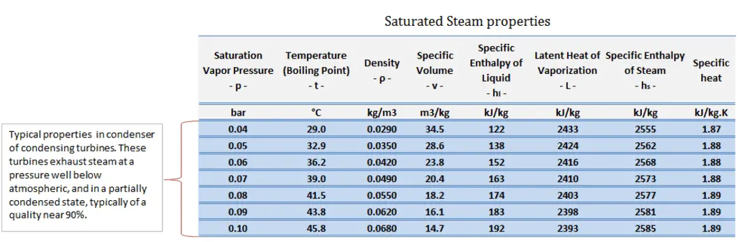
The condenser must maintain a sufficient low vacuum in order to increase the power plant efficiency. The vacuum pumps maintain a sufficient vacuum in the condenser by extracting air and uncondensed gases. The lowest feasible condenser pressure is the saturation pressure corresponding to the ambient temperature (e.g. absolute pressure of 0.008 MPa, which corresponds to 41.5°C). Note that, there is always a temperature difference between (around ΔT = 14°C) the condenser temperature and the ambient temperature, which originates from finite size and efficiency of condensers. Since neither the condenser is 100% efficient heat exchanger, there is always a temperature difference between the saturation temperature (secondary side) and the temperature of the coolant in the cooling system. Moreover, there is a design inefficiciency, which decreases the overall efficiency of the turbine. Ideally the steam exhausted into the condenser would have no subcooling. But real condensers are designed to subcool the liquid by a few degrees of Celsius in order to avoid the suction cavitation in the condensate pumps. But, this subcooling increases the inefficiency of the cycle, because more energy is needed to reheat the water.

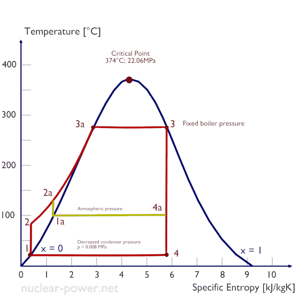
Rankine Cycle - condenser pressure
Decreasing the turbine exhaust pressure increases the net work per cycle but also decreses the vapor quality of outlet steam.

The goal of maintaining the lowest practical turbine exhaust pressure is a primary reason for including the condenser in a thermal power plant. The condenser provides a vacuum that maximizes the energy extracted from the steam, resulting in a significant increase in net work and thermal efficiency. But also this parameter (condenser pressure) has its engineering limits:

  • Decreasing the turbine exhaust pressure decreases the vapor quality (or dryness fraction). At some point the expansion must be ended to avoid damages that could be caused to blades of steam turbine by low quality steam.
  • Decreasing the turbine exhaust pressure significantly increases the specific volume of exhausted steam, which requires huge blades in last rows of low-pressure stage of the steam turbine.

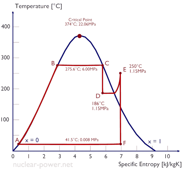
In a typical wet steam turbine, the exhausted steam condenses in the condenser and it is at a pressure well below atmospheric (absolute pressure of 0.008 MPa, which corresponds to 41.5°C). This steam is in a partially condensed state (point F), typically of a quality near 90%. Note that, the pressure inside the condenser is also dependent on the ambient atmospheric conditions:

  • air temperature, pressure and humidity in case of cooling into the atmosphere
  • water temperature and the flow rate in case of cooling into a river or sea

An increase in the ambient temperature causes a proportional increase in pressure of exhausted steam (ΔT = 14°C is usually a constant) hence the thermal efficiency of the power conversion system decreases. In other words, the electrical output of a power plant may vary with ambient conditions, while the thermal power remains constant.

To maintain the parameters inside the condenser (0.008 MPa and 41.5 °C), the cooling water from cooling system must be sufficiently cold and there cannot be large temperature difference between the outlet and inlet water temperauter, hence the flowrate through the cooling system must be very high. The flowrate through the cooling system (with wet cooling towers) may be up to 100 000 m3/h (27.7 m3/s). The condenser inlet water may have about 22°C (strongly depending on ambient conditions), while the condenser outlet may have about 25°C. The sea water cooling systems operate at higher flowrates, for example, 130 000 m3/h.

 
References:
Nuclear and Reactor Physics:
  1. J. R. Lamarsh, Introduction to Nuclear Reactor Theory, 2nd ed., Addison-Wesley, Reading, MA (1983).
  2. J. R. Lamarsh, A. J. Baratta, Introduction to Nuclear Engineering, 3d ed., Prentice-Hall, 2001, ISBN: 0-201-82498-1.
  3. W. M. Stacey, Nuclear Reactor Physics, John Wiley & Sons, 2001, ISBN: 0- 471-39127-1.
  4. Glasstone, Sesonske. Nuclear Reactor Engineering: Reactor Systems Engineering, Springer; 4th edition, 1994, ISBN: 978-0412985317
  5. W.S.C. Williams. Nuclear and Particle Physics. Clarendon Press; 1 edition, 1991, ISBN: 978-0198520467
  6. Kenneth S. Krane. Introductory Nuclear Physics, 3rd Edition, Wiley, 1987, ISBN: 978-0471805533
  7. G.R.Keepin. Physics of Nuclear Kinetics. Addison-Wesley Pub. Co; 1st edition, 1965
  8. Robert Reed Burn, Introduction to Nuclear Reactor Operation, 1988.
  9. U.S. Department of Energy, Nuclear Physics and Reactor Theory. DOE Fundamentals Handbook, Volume 1 and 2. January 1993.

Advanced Reactor Physics:

  1. K. O. Ott, W. A. Bezella, Introductory Nuclear Reactor Statics, American Nuclear Society, Revised edition (1989), 1989, ISBN: 0-894-48033-2.
  2. K. O. Ott, R. J. Neuhold, Introductory Nuclear Reactor Dynamics, American Nuclear Society, 1985, ISBN: 0-894-48029-4.
  3. D. L. Hetrick, Dynamics of Nuclear Reactors, American Nuclear Society, 1993, ISBN: 0-894-48453-2.
  4. E. E. Lewis, W. F. Miller, Computational Methods of Neutron Transport, American Nuclear Society, 1993, ISBN: 0-894-48452-4.

Other References:

Diesel Engine – Car Recycling

See also:

Main Condenser

We hope, this article, Parameter and Operation of the Main Condenser, helps you. If so, give us a like in the sidebar. Main purpose of this website is to help the public to learn some interesting and important information about thermal engineering.
What is Type of Steam Condensers – Definition

Types of Steam Condensers. The steam condensers are broadly classified into two types. Jet condenser and surface condenser. Thermal Engineering

Types of Steam Condensers

The steam condensers are broadly classified into two types:

  • Surface condensers (or non-mixing type condensers). In surface condensers, there is no direct contact between the exhaust steam and the cooling water.
  • Jet condensers (or mixing type condensers). In jet condensers there is direct contact between the exhaust steam and cooling water.

Surface Condenser

The surface condenser is designed to condense and deaerate the exhaust steam from the main turbine and provide a heat sink for the turbine bypass system. In surface condensers, there is no direct contact between the exhaust steam and the cooling water. The exhausted steam from the LP turbines is condensed by passing over tubes containing water from the cooling system. The steam condenses when it comes in contact with the cold surface of the tubes and due to the heat transfer to cooling water by conduction and convection. These tubes are usually made of stainless steel, copper alloys, or titanium depending on several selection criteria (such as thermal conductivity or corrosion resistance).  Titanium condenser tubes are usually the best technical choice, however titanium is very expensive material and the use of titanium condenser tubes is associated with very high initial costs. In general, there are two types of surface condensers:

  • water-cooled surface condenser
  • air-cooled surface condenser

In thermal power plants, where cooling water is in short supply, an air-cooled condenser can be used. An air-cooled condenser is however, significantly more expensive and cannot achieve as low a steam turbine exhaust pressure (and temperature) as a water-cooled surface condenser.

The water gets warmed in the condenser is discharged into the cooling system (i.e. cooling tower, river, sea, or cooling pond). The condensate collected from these condensers is reused as feedwater in the boiler. Since the cooling water and steam do not mix, the condensate is recovered and any kind of cooling water can be used. In comparison to jet condensers, in surface condensers a high vacuum can be maintained, therefore greater thermal efficiency can be achieved. On the other hand, surface condensers are bulky, requires large area and high capital costs. But these capital costs can be recovered by the improved thermal efficiency (i.e. higher )saving in running cost.

Thus, these condensers are most suitable for modern thermal power plants. These are generally used where a large quantity of inferior water is available and better quality of feedwater is to be supplied to the boiler.

Jet Condenser

In jet condensers, the cooling water is sprayed on the exhaust steam and there is direct contact between the exhaust steam and cooling water. The process of condensation is very fast and efficient, but here cooling water and condensed steam are mixed up. The condensate then cannot be reused as feedwater to the boilers. The temperature of the condensate is same as that of the cooling water leaving the condenser. Due to more intimate mixing of steam and cooling water jet condenser requires less quantity of cooling water for the condensation of steam. In general, jet condensers require less building space and they are simpler in construction and lower in capital cost. Despite these advantages jet condensers are not usual in thermal power plants especially due to the loss of condensate.

 
References:
Nuclear and Reactor Physics:
  1. J. R. Lamarsh, Introduction to Nuclear Reactor Theory, 2nd ed., Addison-Wesley, Reading, MA (1983).
  2. J. R. Lamarsh, A. J. Baratta, Introduction to Nuclear Engineering, 3d ed., Prentice-Hall, 2001, ISBN: 0-201-82498-1.
  3. W. M. Stacey, Nuclear Reactor Physics, John Wiley & Sons, 2001, ISBN: 0- 471-39127-1.
  4. Glasstone, Sesonske. Nuclear Reactor Engineering: Reactor Systems Engineering, Springer; 4th edition, 1994, ISBN: 978-0412985317
  5. W.S.C. Williams. Nuclear and Particle Physics. Clarendon Press; 1 edition, 1991, ISBN: 978-0198520467
  6. Kenneth S. Krane. Introductory Nuclear Physics, 3rd Edition, Wiley, 1987, ISBN: 978-0471805533
  7. G.R.Keepin. Physics of Nuclear Kinetics. Addison-Wesley Pub. Co; 1st edition, 1965
  8. Robert Reed Burn, Introduction to Nuclear Reactor Operation, 1988.
  9. U.S. Department of Energy, Nuclear Physics and Reactor Theory. DOE Fundamentals Handbook, Volume 1 and 2. January 1993.

Advanced Reactor Physics:

  1. K. O. Ott, W. A. Bezella, Introductory Nuclear Reactor Statics, American Nuclear Society, Revised edition (1989), 1989, ISBN: 0-894-48033-2.
  2. K. O. Ott, R. J. Neuhold, Introductory Nuclear Reactor Dynamics, American Nuclear Society, 1985, ISBN: 0-894-48029-4.
  3. D. L. Hetrick, Dynamics of Nuclear Reactors, American Nuclear Society, 1993, ISBN: 0-894-48453-2.
  4. E. E. Lewis, W. F. Miller, Computational Methods of Neutron Transport, American Nuclear Society, 1993, ISBN: 0-894-48452-4.

Other References:

Diesel Engine – Car Recycling

See also:

Main Condenser

We hope, this article, Type of Steam Condensers, helps you. If so, give us a like in the sidebar. Main purpose of this website is to help the public to learn some interesting and important information about thermal engineering.
What is Surface Condenser and Jet Condenser – Definition

In surface condensers, there is no direct contact between the exhaust steam and the cooling water. They are designed to condense and deaerate the exhaust steam. Surface Condenser and Jet Condenser

Surface Condenser

The steam condensers are broadly classified into two types:

  • Surface condensers (or non-mixing type condensers). In surface condensers, there is no direct contact between the exhaust steam and the cooling water.
  • Jet condensers (or mixing type condensers). In jet condensers there is direct contact between the exhaust steam and cooling water.

Surface Condenser

The surface condenser is designed to condense and deaerate the exhaust steam from the main turbine and provide a heat sink for the turbine bypass system. In surface condensers, there is no direct contact between the exhaust steam and the cooling water. The exhausted steam from the LP turbines is condensed by passing over tubes containing water from the cooling system. The steam condenses when it comes in contact with the cold surface of the tubes and due to the heat transfer to cooling water by conduction and convection. These tubes are usually made of stainless steel, copper alloys, or titanium depending on several selection criteria (such as thermal conductivity or corrosion resistance).  Titanium condenser tubes are usually the best technical choice, however titanium is very expensive material and the use of titanium condenser tubes is associated with very high initial costs. In general, there are two types of surface condensers:

  • water-cooled surface condenser
  • air-cooled surface condenser

In thermal power plants, where cooling water is in short supply, an air-cooled condenser can be used. An air-cooled condenser is however, significantly more expensive and cannot achieve as low a steam turbine exhaust pressure (and temperature) as a water-cooled surface condenser.

The water gets warmed in the condenser is discharged into the cooling system (i.e. cooling tower, river, sea, or cooling pond). The condensate collected from these condensers is reused as feedwater in the boiler. Since the cooling water and steam do not mix, the condensate is recovered and any kind of cooling water can be used. In comparison to jet condensers, in surface condensers a high vacuum can be maintained, therefore greater thermal efficiency can be achieved. On the other hand, surface condensers are bulky, requires large area and high capital costs. But these capital costs can be recovered by the improved thermal efficiency (i.e. higher )saving in running cost.

Thus, these condensers are most suitable for modern thermal power plants. These are generally used where a large quantity of inferior water is available and better quality of feedwater is to be supplied to the boiler.

Jet Condenser

In jet condensers, the cooling water is sprayed on the exhaust steam and there is direct contact between the exhaust steam and cooling water. The process of condensation is very fast and efficient, but here cooling water and condensed steam are mixed up. The condensate then cannot be reused as feedwater to the boilers. The temperature of the condensate is same as that of the cooling water leaving the condenser. Due to more intimate mixing of steam and cooling water jet condenser requires less quantity of cooling water for the condensation of steam. In general, jet condensers require less building space and they are simpler in construction and lower in capital cost. Despite these advantages jet condensers are not usual in thermal power plants especially due to the loss of condensate.

Main Condenser

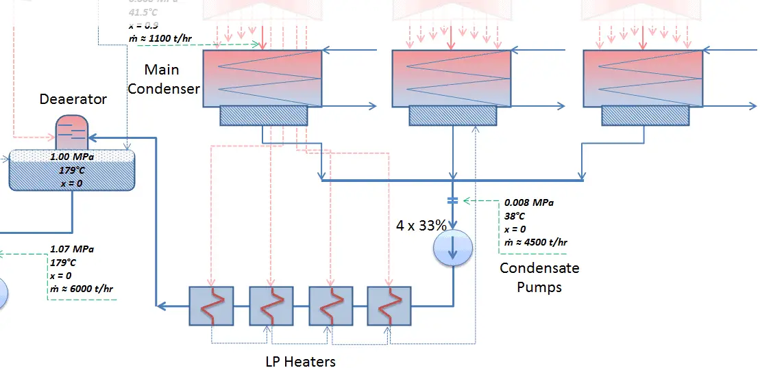
Condenser - LP Heaters - DeaeratorThe main steam condenser (MC) system is designed to condense and deaerate the exhaust steam from the main turbine and provide a heat sink for the turbine bypass system. In thermal power plants, there are usually surface condensers as the main condenser. The exhausted steam from the LP turbines is condensed by passing over tubes containing water from the cooling system. There is a main condenser unit under each LP turbine, usually below the turbine with its axis perpendicular to the turbine axis. Since nuclear power plants usually contain also an auxiliary condenser (e.g. to condense steam from steam driven feedwater pumps), engineers use the term “main condenser“.

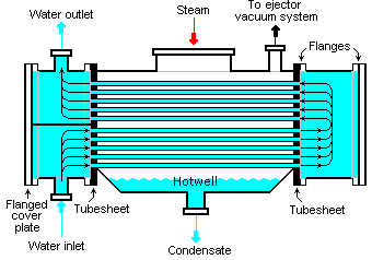
Surface Condenser Source: wikipedia.org License: CC BY-SA 3.0
Surface Condenser

The pressure inside condenser is given by the ambient air temperature (i.e. temperature of water in the cooling system) and by steam ejectors or vacuum pumps, which pull the gases (non-condensibles) from the surface condenser and eject them to the atmosphere. The pressure inside condenser determines the overall power output of the power conversion system. Thermal power plants are usually equipped with so called “surface condensers”.

The condensed steam (now called condensate) is collected in the condenser’s hotwell. Condenser’s hotwell provides also a water storage capacity, which is required for operational purposes such as feedwater makeup. The condensate (saturated or slightly subcooled liquid) is delivered to the condensate pump and then pumped by condensate pumps to the deaerator through feedwater heating system. The condensate pumps increase the pressure usually to about p = 1-2 MPa. There are usually four one-third-capacity centrifugal condensate pumps with common suction and discharge headers. Three pumps are normally in operation with one in the backup.

 
Isobaric Heat Rejection
Isobaric heat rejection (in a heat exchanger) – In this phase the cycle completes by a constant-pressure process in which heat is rejected from the partially condensed steam. There is heat transfer from the vapor to cooling water flowing in a cooling circuit. The vapor condenses and the temperature of the cooling water increases. The net heat rejected is given by Qre = H4 – H1

Parameters of the Main Condenser

The condenser must maintain a sufficient low vacuum in order to increase the power plant efficiency. The vacuum pumps maintain a sufficient vacuum in the condenser by extracting air and uncondensed gases. The lowest feasible condenser pressure is the saturation pressure corresponding to the ambient temperature (e.g. absolute pressure of 0.008 MPa, which corresponds to 41.5°C). Note that, there is always a temperature difference between (around ΔT = 14°C) the condenser temperature and the ambient temperature, which originates from finite size and efficiency of condensers. Since neither the condenser is 100% efficient heat exchanger, there is always a temperature difference between the saturation temperature (secondary side) and the temperature of the coolant in the cooling system. Moreover, there is a design inefficiciency, which decreases the overall efficiency of the turbine. Ideally the steam exhausted into the condenser would have no subcooling. But real condensers are designed to subcool the liquid by a few degrees of Celsius in order to avoid the suction cavitation in the condensate pumps. But, this subcooling increases the inefficiency of the cycle, because more energy is needed to reheat the water.

Rankine Cycle - condenser pressure
Decreasing the turbine exhaust pressure increases the net work per cycle but also decreses the vapor quality of outlet steam.

The goal of maintaining the lowest practical turbine exhaust pressure is a primary reason for including the condenser in a thermal power plant. The condenser provides a vacuum that maximizes the energy extracted from the steam, resulting in a significant increase in net work and thermal efficiency. But also this parameter (condenser pressure) has its engineering limits:

  • Decreasing the turbine exhaust pressure decreases the vapor quality (or dryness fraction). At some point the expansion must be ended to avoid damages that could be caused to blades of steam turbine by low quality steam.
  • Decreasing the turbine exhaust pressure significantly increases the specific volume of exhausted steam, which requires huge blades in last rows of low-pressure stage of the steam turbine.

In a typical wet steam turbine, the exhausted steam condenses in the condenser and it is at a pressure well below atmospheric (absolute pressure of 0.008 MPa, which corresponds to 41.5°C). This steam is in a partially condensed state (point F), typically of a quality near 90%. Note that, the pressure inside the condenser is also dependent on the ambient atmospheric conditions:

  • air temperature, pressure and humidity in case of cooling into the atmosphere
  • water temperature and the flow rate in case of cooling into a river or sea

An increase in the ambient temperature causes a proportional increase in pressure of exhausted steam (ΔT = 14°C is usually a constant) hence the thermal efficiency of the power conversion system decreases. In other words, the electrical output of a power plant may vary with ambient conditions, while the thermal power remains constant.

To maintain the parameters inside the condenser (0.008 MPa and 41.5 °C), the cooling water from cooling system must be sufficiently cold and there cannot be large temperature difference between the outlet and inlet water temperauter, hence the flowrate through the cooling system must be very high. The flowrate through the cooling system (with wet cooling towers) may be up to 100 000 m3/h (27.7 m3/s). The condenser inlet water may have about 22°C (strongly depending on ambient conditions), while the condenser outlet may have about 25°C. The sea water cooling systems operate at higher flowrates, for example, 130 000 m3/h.

 
References:
Nuclear and Reactor Physics:
  1. J. R. Lamarsh, Introduction to Nuclear Reactor Theory, 2nd ed., Addison-Wesley, Reading, MA (1983).
  2. J. R. Lamarsh, A. J. Baratta, Introduction to Nuclear Engineering, 3d ed., Prentice-Hall, 2001, ISBN: 0-201-82498-1.
  3. W. M. Stacey, Nuclear Reactor Physics, John Wiley & Sons, 2001, ISBN: 0- 471-39127-1.
  4. Glasstone, Sesonske. Nuclear Reactor Engineering: Reactor Systems Engineering, Springer; 4th edition, 1994, ISBN: 978-0412985317
  5. W.S.C. Williams. Nuclear and Particle Physics. Clarendon Press; 1 edition, 1991, ISBN: 978-0198520467
  6. Kenneth S. Krane. Introductory Nuclear Physics, 3rd Edition, Wiley, 1987, ISBN: 978-0471805533
  7. G.R.Keepin. Physics of Nuclear Kinetics. Addison-Wesley Pub. Co; 1st edition, 1965
  8. Robert Reed Burn, Introduction to Nuclear Reactor Operation, 1988.
  9. U.S. Department of Energy, Nuclear Physics and Reactor Theory. DOE Fundamentals Handbook, Volume 1 and 2. January 1993.

Advanced Reactor Physics:

  1. K. O. Ott, W. A. Bezella, Introductory Nuclear Reactor Statics, American Nuclear Society, Revised edition (1989), 1989, ISBN: 0-894-48033-2.
  2. K. O. Ott, R. J. Neuhold, Introductory Nuclear Reactor Dynamics, American Nuclear Society, 1985, ISBN: 0-894-48029-4.
  3. D. L. Hetrick, Dynamics of Nuclear Reactors, American Nuclear Society, 1993, ISBN: 0-894-48453-2.
  4. E. E. Lewis, W. F. Miller, Computational Methods of Neutron Transport, American Nuclear Society, 1993, ISBN: 0-894-48452-4.

Other References:

Diesel Engine – Car Recycling

See also:

Main Condenser

We hope, this article, Surface Condenser and Jet Condenser, helps you. If so, give us a like in the sidebar. Main purpose of this website is to help the public to learn some interesting and important information about thermal engineering.
What is Cooling System – Circulating Water System – Definition

The cooling system or the circulating water system provides a continuous supply of cooling water to the main condenser to remove the heat rejected by the turbine and auxiliary systems. Thermal Engineering

Cooling System – Circulating Water System

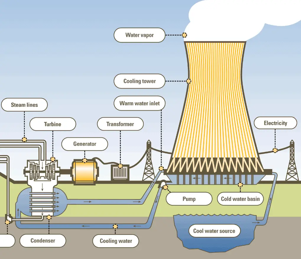
Cooling System - Cooling TowerThe cooling system or the circulating water system provides a continuous supply of cooling water to the main condenser to remove the heat rejected by the turbine and auxiliary systems (e.g. the turbine bypass system).  In this process the cooling water becomes hot. This energy is rejected to the atmosphere via cooling towers or directly to the seawater or to a river. Note that, not all nuclear power plants have cooling towers and conversely, the same kind of cooling towers are often used at large coal-fired power plants as well.

Cooling System in Wet Steam Turbines

In a typical condensing steam turbine, the exhausted steam condenses in the condenser and it is at a pressure well below atmospheric (absolute pressure of 0.008 MPa, which corresponds to 41.5°C). This steam is in a partially condensed state (point F), typically of a quality near 90%.

Rankine Cycle - Ts diagram
Rankine cycle – Ts diagram

The pressure inside condenser (thus the enthalpy of outlet steam) is given by the ambient air temperature (i.e. temperature of water in the cooling system). and other parameters:

  • air temperature, pressure and humidity in case of cooling into the atmosphere
  • water temperature and the flow rate in case of cooling into a river or sea

An increase in the ambient temperature may cause a proportional increase in pressure of exhausted steam (ΔT = 14°C is usually a constant) hence the thermal efficiency of the power conversion system may decrease. In other words, the electrical output of a power plant may vary with ambient conditions, while the thermal power remains constant.

It must be noted there is also lower limit for the steam outlet temperature, thus for the cooling system. Below 0.008 MPa and 41.5 °C the specific volume of exhausted steam significantly increases which requires huge blades in last rows of low-pressure stage of the steam turbine. Moreover, with a decrease in the turbine exhaust pressure the vapor quality decreases (or dryness fraction). At some point the expansion must be ended to avoid damages that could be caused to blades of steam turbine by low quality steam.

Typical parameters in a condenser of condensing turbines

In modern nuclear power plants the overall thermal efficiency is about one-third (33%), so 3000 MWth of thermal power from the fission reaction is needed to generate 1000 MWe of electrical power. Therefore about 2000MWth of unusable energy must be rejected in order to fulfill the second law of thermodynamics.

To maintain the parameters inside the condenser (0.008 MPa and 41.5 °C), the cooling water must be sufficiently cold and there cannot be large temperature difference between the outlet and inlet water temperauter, hence the flowrate through the cooling system must be very high. The flowrate through the cooling system (with wet cooling towers) may be up to 100 000 m3/h (27.7 m3/s). The condenser inlet water may have about 22°C (strongly depending on ambient conditions), while the condenser outlet may have about 25°C.

The sea water cooling systems operate at higher flowrates, for example, 130 000 m3/h. In general, the energy can be rejected to the atmosphere via cooling towers or directly to the seawater or to a river.

Condenser - LP Heaters - Deaerator

Cooling Towers

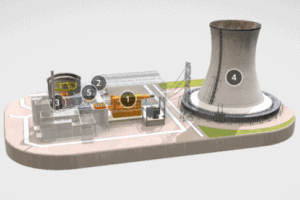
The cooling towers are devices that reject waste heat to the atmosphere through the cooling of a water stream to a lower temperature. Cooling towers are built on places where is scarcity of the water. By using cooling towers the cooling water requirement is reduced and only makeup water is to be supplied. The cooling towers significantly reduce the cooling water demand but it is achieved at the expense of large capital costs.

With respect to the heat transfer mechanism employed, the main types are:

Dry cooling towers operate by heat transfer through a surface that separates the working fluid from ambient air, such as in a tube to air heat exchanger, utilizing convective heat transfer. They do not use evaporation, hence the consumption of makeup water is minimal.

Wet cooling towers (or open circuit cooling towers) operate on the principle of evaporative cooling. Evaporative cooling is the addition of water vapor into air, which causes a lowering of the temperature of the air and the water too. The energy needed to evaporate the water is taken from the remaining mass of water, thus reducing its temperature. The cooling water from the plant is pumped to a height of about 10 m and distributed over the cooling tower fill, cascading down the fill to the well at the bottom. Inside the wet cooling tower, fills are added to increase contact surface as well as contact time between air and water, to provide better heat transfer.

Nearly all nuclear power plants, which use cooling towers, use the wet cooling towers based on the principle of evaporative cooling. Some water about 1% goes into air in the form of water vapor by absorbing its latent heat of vaporization from the remaining water and thus causes the reduction in the water temperature as ambient air is drawn past a flow of water. The remaining water (cooled) is collected in a sump at the bottom of the tower and returned back to the condenser.

The types of cooling towers on the basis of the draught (method of air circulation) are:

  • Natural draught cooling towers. Natural draught cooling towers utilize buoyancy via a tall hyperboloid chimney. Hyperboloid cooling towers are typical for natural draught cooling towers because of their structural strength and because of the fact that the hyperboloid shape also aids in accelerating the upward convective air flow, improving cooling efficiency. In this cooling tower the hot cooling water (e.g. 25°C) from the condenser is pumped to a height of about 10 m, enters the tower and then sprayed over the trays. Water droplets fall down and meets the colder air entering from the bottom of the tower which is open to the atmosphere. Hot water (e.g. 25°C) gives up its heat to the air and gets cooled (e.g. 22°C). Warm, moist air naturally rises due to the density differential compared to the dry, cooler outside air. Warm moist air is less dense than drier air at the same pressure. This moist air buoyancy produces an upwards current of air through the hyperboloid tower. The cooled water falls down in the form of rain and gets collected in the pond at the bottom of the tower.
  • Mechanical draught cooling towers. In general, in the mechanical draught cooling towers the air is circulated with the use of a mechanical device like a fan or a blower.
    • Forced draught cooling towers. Forced draught cooling towers uses the fan, which  is installed at the bottom of the tower. This produces high entering and low exiting air velocities, therefore this towers are much more susceptible to recirculation.
    • Induced draught cooling towers. Induced draught cooling towers uses the fan, which  is installed at the top of the tower. This produces low entering and high exiting air velocities, reducing the possibility of recirculation in which discharged air flows back into the air intake.
 
References:
Nuclear and Reactor Physics:
  1. J. R. Lamarsh, Introduction to Nuclear Reactor Theory, 2nd ed., Addison-Wesley, Reading, MA (1983).
  2. J. R. Lamarsh, A. J. Baratta, Introduction to Nuclear Engineering, 3d ed., Prentice-Hall, 2001, ISBN: 0-201-82498-1.
  3. W. M. Stacey, Nuclear Reactor Physics, John Wiley & Sons, 2001, ISBN: 0- 471-39127-1.
  4. Glasstone, Sesonske. Nuclear Reactor Engineering: Reactor Systems Engineering, Springer; 4th edition, 1994, ISBN: 978-0412985317
  5. W.S.C. Williams. Nuclear and Particle Physics. Clarendon Press; 1 edition, 1991, ISBN: 978-0198520467
  6. Kenneth S. Krane. Introductory Nuclear Physics, 3rd Edition, Wiley, 1987, ISBN: 978-0471805533
  7. G.R.Keepin. Physics of Nuclear Kinetics. Addison-Wesley Pub. Co; 1st edition, 1965
  8. Robert Reed Burn, Introduction to Nuclear Reactor Operation, 1988.
  9. U.S. Department of Energy, Nuclear Physics and Reactor Theory. DOE Fundamentals Handbook, Volume 1 and 2. January 1993.

Advanced Reactor Physics:

  1. K. O. Ott, W. A. Bezella, Introductory Nuclear Reactor Statics, American Nuclear Society, Revised edition (1989), 1989, ISBN: 0-894-48033-2.
  2. K. O. Ott, R. J. Neuhold, Introductory Nuclear Reactor Dynamics, American Nuclear Society, 1985, ISBN: 0-894-48029-4.
  3. D. L. Hetrick, Dynamics of Nuclear Reactors, American Nuclear Society, 1993, ISBN: 0-894-48453-2.
  4. E. E. Lewis, W. F. Miller, Computational Methods of Neutron Transport, American Nuclear Society, 1993, ISBN: 0-894-48452-4.

Other References:

Diesel Engine – Car Recycling

See also:

Turbine Generator

We hope, this article, Cooling System – Circulating Water System, helps you. If so, give us a like in the sidebar. Main purpose of this website is to help the public to learn some interesting and important information about thermal engineering.
What is Cooling Tower – Dry, Wet – Natural draught – Definition

The cooling towers are devices that reject waste heat to the atmosphere. Two basic types are: wet cooling towers and dry cooling towers. Natural draught cooling towers. Thermal Engineering

Cooling Towers

Cooling System - Cooling TowerThe cooling towers are devices that reject waste heat to the atmosphere through the cooling of a water stream to a lower temperature. Cooling towers are built on places where is scarcity of the water. By using cooling towers the cooling water requirement is reduced and only makeup water is to be supplied. The cooling towers significantly reduce the cooling water demand but it is achieved at the expense of large capital costs.

With respect to the heat transfer mechanism employed, the main types are:

Dry cooling towers operate by heat transfer through a surface that separates the working fluid from ambient air, such as in a tube to air heat exchanger, utilizing convective heat transfer. They do not use evaporation, hence the consumption of makeup water is minimal.

Wet cooling towers (or open circuit cooling towers) operate on the principle of evaporative cooling. Evaporative cooling is the addition of water vapor into air, which causes a lowering of the temperature of the air and the water too. The energy needed to evaporate the water is taken from the remaining mass of water, thus reducing its temperature. The cooling water from the plant is pumped to a height of about 10 m and distributed over the cooling tower fill, cascading down the fill to the well at the bottom. Inside the wet cooling tower, fills are added to increase contact surface as well as contact time between air and water, to provide better heat transfer.

Nearly all nuclear power plants, which use cooling towers, use the wet cooling towers based on the principle of evaporative cooling. Some water about 1% goes into air in the form of water vapor by absorbing its latent heat of vaporization from the remaining water and thus causes the reduction in the water temperature as ambient air is drawn past a flow of water. The remaining water (cooled) is collected in a sump at the bottom of the tower and returned back to the condenser.

The types of cooling towers on the basis of the draught (method of air circulation) are:

  • Natural draught cooling towers. Natural draught cooling towers utilize buoyancy via a tall hyperboloid chimney. Hyperboloid cooling towers are typical for natural draught cooling towers because of their structural strength and because of the fact that the hyperboloid shape also aids in accelerating the upward convective air flow, improving cooling efficiency. In this cooling tower the hot cooling water (e.g. 25°C) from the condenser is pumped to a height of about 10 m, enters the tower and then sprayed over the trays. Water droplets fall down and meets the colder air entering from the bottom of the tower which is open to the atmosphere. Hot water (e.g. 25°C) gives up its heat to the air and gets cooled (e.g. 22°C). Warm, moist air naturally rises due to the density differential compared to the dry, cooler outside air. Warm moist air is less dense than drier air at the same pressure. This moist air buoyancy produces an upwards current of air through the hyperboloid tower. The cooled water falls down in the form of rain and gets collected in the pond at the bottom of the tower.
  • Mechanical draught cooling towers. In general, in the mechanical draught cooling towers the air is circulated with the use of a mechanical device like a fan or a blower.
    • Forced draught cooling towers. Forced draught cooling towers uses the fan, which  is installed at the bottom of the tower. This produces high entering and low exiting air velocities, therefore this towers are much more susceptible to recirculation.
    • Induced draught cooling towers. Induced draught cooling towers uses the fan, which  is installed at the top of the tower. This produces low entering and high exiting air velocities, reducing the possibility of recirculation in which discharged air flows back into the air intake.

Special link: 3D model of NPP – sketchfab.com

nuclear power plant-min

Cooling System – Circulating Water System

The cooling system or the circulating water system provides a continuous supply of cooling water to the main condenser to remove the heat rejected by the turbine and auxiliary systems (e.g. the turbine bypass system).  In this process the cooling water becomes hot. This energy is rejected to the atmosphere via cooling towers or directly to the seawater or to a river. Note that, not all nuclear power plants have cooling towers and conversely, the same kind of cooling towers are often used at large coal-fired power plants as well.

Cooling System in Wet Steam Turbines

In a typical condensing steam turbine, the exhausted steam condenses in the condenser and it is at a pressure well below atmospheric (absolute pressure of 0.008 MPa, which corresponds to 41.5°C). This steam is in a partially condensed state (point F), typically of a quality near 90%.

Rankine Cycle - Ts diagram
Rankine cycle – Ts diagram

The pressure inside condenser (thus the enthalpy of outlet steam) is given by the ambient air temperature (i.e. temperature of water in the cooling system). and other parameters:

  • air temperature, pressure and humidity in case of cooling into the atmosphere
  • water temperature and the flow rate in case of cooling into a river or sea

An increase in the ambient temperature may cause a proportional increase in pressure of exhausted steam (ΔT = 14°C is usually a constant) hence the thermal efficiency of the power conversion system may decrease. In other words, the electrical output of a power plant may vary with ambient conditions, while the thermal power remains constant.

It must be noted there is also lower limit for the steam outlet temperature, thus for the cooling system. Below 0.008 MPa and 41.5 °C the specific volume of exhausted steam significantly increases which requires huge blades in last rows of low-pressure stage of the steam turbine. Moreover, with a decrease in the turbine exhaust pressure the vapor quality decreases (or dryness fraction). At some point the expansion must be ended to avoid damages that could be caused to blades of steam turbine by low quality steam.

Typical parameters in a condenser of condensing turbines

In modern nuclear power plants the overall thermal efficiency is about one-third (33%), so 3000 MWth of thermal power from the fission reaction is needed to generate 1000 MWe of electrical power. Therefore about 2000MWth of unusable energy must be rejected in order to fulfill the second law of thermodynamics.

To maintain the parameters inside the condenser (0.008 MPa and 41.5 °C), the cooling water must be sufficiently cold and there cannot be large temperature difference between the outlet and inlet water temperauter, hence the flowrate through the cooling system must be very high. The flowrate through the cooling system (with wet cooling towers) may be up to 100 000 m3/h (27.7 m3/s). The condenser inlet water may have about 22°C (strongly depending on ambient conditions), while the condenser outlet may have about 25°C.

The sea water cooling systems operate at higher flowrates, for example, 130 000 m3/h. In general, the energy can be rejected to the atmosphere via cooling towers or directly to the seawater or to a river.

Condenser - LP Heaters - Deaerator

 
References:
Nuclear and Reactor Physics:
  1. J. R. Lamarsh, Introduction to Nuclear Reactor Theory, 2nd ed., Addison-Wesley, Reading, MA (1983).
  2. J. R. Lamarsh, A. J. Baratta, Introduction to Nuclear Engineering, 3d ed., Prentice-Hall, 2001, ISBN: 0-201-82498-1.
  3. W. M. Stacey, Nuclear Reactor Physics, John Wiley & Sons, 2001, ISBN: 0- 471-39127-1.
  4. Glasstone, Sesonske. Nuclear Reactor Engineering: Reactor Systems Engineering, Springer; 4th edition, 1994, ISBN: 978-0412985317
  5. W.S.C. Williams. Nuclear and Particle Physics. Clarendon Press; 1 edition, 1991, ISBN: 978-0198520467
  6. Kenneth S. Krane. Introductory Nuclear Physics, 3rd Edition, Wiley, 1987, ISBN: 978-0471805533
  7. G.R.Keepin. Physics of Nuclear Kinetics. Addison-Wesley Pub. Co; 1st edition, 1965
  8. Robert Reed Burn, Introduction to Nuclear Reactor Operation, 1988.
  9. U.S. Department of Energy, Nuclear Physics and Reactor Theory. DOE Fundamentals Handbook, Volume 1 and 2. January 1993.

Advanced Reactor Physics:

  1. K. O. Ott, W. A. Bezella, Introductory Nuclear Reactor Statics, American Nuclear Society, Revised edition (1989), 1989, ISBN: 0-894-48033-2.
  2. K. O. Ott, R. J. Neuhold, Introductory Nuclear Reactor Dynamics, American Nuclear Society, 1985, ISBN: 0-894-48029-4.
  3. D. L. Hetrick, Dynamics of Nuclear Reactors, American Nuclear Society, 1993, ISBN: 0-894-48453-2.
  4. E. E. Lewis, W. F. Miller, Computational Methods of Neutron Transport, American Nuclear Society, 1993, ISBN: 0-894-48452-4.

Other References:

Diesel Engine – Car Recycling

See also:

Turbine Generator

We hope, this article, Cooling Tower – Dry, Wet – Natural draught, helps you. If so, give us a like in the sidebar. Main purpose of this website is to help the public to learn some interesting and important information about thermal engineering.
What is Main Generator – Electric Generator – Turbo-alternator – Definition

Main Generator – Electric Generator – Turbo-alternator. A generator, or electric generator is a device that converts mechanical energy of the steam turbine to electrical energy. Thermal Engineering

Main Generator – Electric Generator – Turbo-alternator

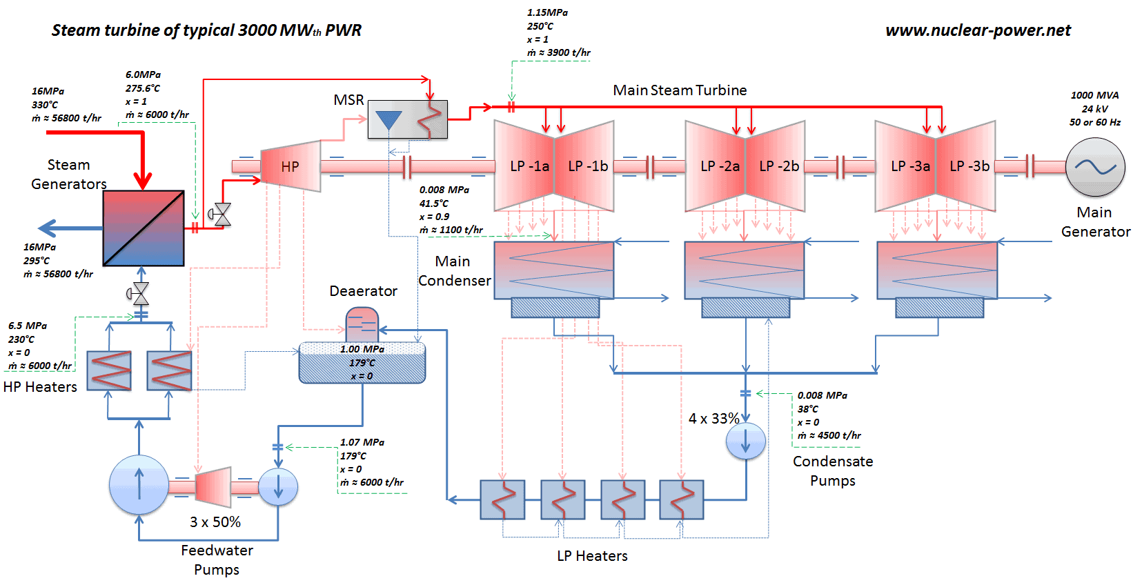
Steam turbine of typical 3000MWth PWR
Schema of a steam turbine of a typical 3000MWth PWR.

A generator, or electric generator is a device that converts mechanical energy of the steam turbine to electrical energy. Since any AC electric generator can be called an alternator, for large power plants engineers also use the term turbo-alternator, which refers to alternators driven by steam turbines. Since the turbo-alternator usually consists of two parts, the larger of the two sections is the main generator and the smaller one is the exciter. In thermal power plants, there is usually one main generator, which provides all of the power for electric power grids. A steam turbine is usually on the same shaft with a main generator and an exciter.

In general, a main generator consists of a rotating part and a stationary part:

  • Stator. Stator is the stationary part of an electric generator, which surrounds the rotor. The stator has a wire winding in which the changing field induces an electric current
  • Rotor. Rotor is the rotating part of an electric generator and generates a magnetic field.

A typical turbo-alternator in nuclear power plants consists of:

  • Main generator
    • 4-pole hydrogen-cooled rotor.  The rotor winding is made up of hollow conductors through which the hydrogen gas flows. The hydrogen is cooled in the hydrogen/water heat exchangers.
    • Stator with water-cooled winding (demineralized water).
  • Brushless excitation system. Shaft-driven, air-cooled brushless exciter. The exciter keeps a current going through the wires of the rotor. When this rotor turns, it induces a voltage in the stator.

Typically the main generator operates at speeds about:

  • 3000 RPM for 50 Hz systems for 2-pole generator (or 1500RPM for 4-pole generator),
  • 1800 RPM for 60 Hz systems for 4-pole generator (or 3600 RPM for 2-pole generator).

with an output voltage of 24,000 volts (i.e. 24kV), nominal rating – 1111 MVA, efective power – 1000 MWel, power factor – 0,9 and efficiency – 99%.

 
References:
Nuclear and Reactor Physics:
  1. J. R. Lamarsh, Introduction to Nuclear Reactor Theory, 2nd ed., Addison-Wesley, Reading, MA (1983).
  2. J. R. Lamarsh, A. J. Baratta, Introduction to Nuclear Engineering, 3d ed., Prentice-Hall, 2001, ISBN: 0-201-82498-1.
  3. W. M. Stacey, Nuclear Reactor Physics, John Wiley & Sons, 2001, ISBN: 0- 471-39127-1.
  4. Glasstone, Sesonske. Nuclear Reactor Engineering: Reactor Systems Engineering, Springer; 4th edition, 1994, ISBN: 978-0412985317
  5. W.S.C. Williams. Nuclear and Particle Physics. Clarendon Press; 1 edition, 1991, ISBN: 978-0198520467
  6. Kenneth S. Krane. Introductory Nuclear Physics, 3rd Edition, Wiley, 1987, ISBN: 978-0471805533
  7. G.R.Keepin. Physics of Nuclear Kinetics. Addison-Wesley Pub. Co; 1st edition, 1965
  8. Robert Reed Burn, Introduction to Nuclear Reactor Operation, 1988.
  9. U.S. Department of Energy, Nuclear Physics and Reactor Theory. DOE Fundamentals Handbook, Volume 1 and 2. January 1993.

Advanced Reactor Physics:

  1. K. O. Ott, W. A. Bezella, Introductory Nuclear Reactor Statics, American Nuclear Society, Revised edition (1989), 1989, ISBN: 0-894-48033-2.
  2. K. O. Ott, R. J. Neuhold, Introductory Nuclear Reactor Dynamics, American Nuclear Society, 1985, ISBN: 0-894-48029-4.
  3. D. L. Hetrick, Dynamics of Nuclear Reactors, American Nuclear Society, 1993, ISBN: 0-894-48453-2.
  4. E. E. Lewis, W. F. Miller, Computational Methods of Neutron Transport, American Nuclear Society, 1993, ISBN: 0-894-48452-4.

Other References:

Diesel Engine – Car Recycling

See also:

Turbine Generator

We hope, this article, Main Generator – Electric Generator – Turbo-alternator, helps you. If so, give us a like in the sidebar. Main purpose of this website is to help the public to learn some interesting and important information about thermal engineering.

What is Feedwater Heating System – Heat Regeneration – Definition

In general, the feedwater heating system consists of: low-pressure feedwater heaters, deaerator, high-pressure feedwater heaters. The system preheats feedwater up to 230°C. Thermal Engineering

Feedwater Heating System – Heat Regeneration

In general, the feedwater heating system consists of:

  • low-pressure feedwater heaters
  • deaerator
  • high-pressure feedwater heaters

Low-pressure feedwater heaters

Condenser - LP Heaters - DeaeratorThe condensate from condensate pumps then passes through several stages of low pressure feedwater heaters, in which the temperature of the condensate is increased by heat transfer from steam extracted from the low pressure turbines. There are usually three or four stages of low pressure feedwater heaters connected in the cascade. The condensate exits the low pressure feedwater heaters at approximately p = 1 MPa, t = 150°C and enters the deaerator. The main condensate system also contains a mechanical condensate purification system for removing impurities. The feedwater heaters are self-regulating. It means that the greater the flow of feedwater the greater the rate of heat absorption from the steam and the greater the flow of extraction steam.

There are non-return valves in the extraction steam lines between the feedwater heaters and turbine. These non-return valves prevent the reverse steam or water flow in case of turbine trip, which causes rapid decrease in the pressure inside the turbine. Any water entering the turbine in this way could cause severe damage to the turbine blading.

Deaerator

Deaerator
A schematic diagram of a typical tray-type deaerator. Source: wikipedia.org License: CC BY-SA 3.0

In the deaerator, the condensate is heated to saturated conditions usually by the steam extracted from the steam turbine. The extraction steam are mixed in the deaerator by a system of spray nozzles and cascading trays between which the steam percolates. Any dissolved gases in the condensate are released in this process and removed from the deaerator by venting to the atmosphere or to the main condenser. Directly below the deaerator is the feedwater storage tank, in which a large quantity of feedwater is stored at near saturation conditions. In the turbine trip event, this feedwater can be supplied to steam generators to maintain the required water inventory during transient. The deaerator and the storage tank is usually located at a high elevation in the turbine hall to ensure an adequate net positive suction head (NPSH) at the inlet to the feedwater pumps. NPSH is used to measure how close a fluid is to saturated conditions. Lowering the pressure at the suction side can induce cavitation. This arrangement minimizes the risk of cavitation in the pump.

High-pressure feedwater heaters

Feedwater Pumps - HP HeatersThe water discharge from the feedwater pumps flows through the high pressure feedwater heaters, enters the containment and then flows into the steam generators.

The high pressure feedwater heaters are heated by extraction steam from the high pressure turbine, HP Turbine. Drains from the high-pressure feedwater heaters are usually routed to the deaerator.

The feedwater (water 230°C; 446°F; 6,5MPa) is pumped into the steam generator through the feedwater inlet.

 
Heat Regeneration
The process of heat regeneration significantly increases the thermal efficiency of steam turbine by reducing the amount of fuel that must be added in the boiler. This process is known as heat regeneration and a variety of heat regenerators can be used for this purpose. Sometimes engineers use the term economiser that are heat exchangers intended to reduce energy consumption, especially in case of preheating of a fluid. On the other hand, the process of draining steam from the turbine at certain point of its expansion and using this steam for heating the feedwater supplied to the boiler is known as bleeding and it must be noted, a small amount of work, WT, is lost by the turbine.

As can be seen in the article “Steam Generator”, the feedwater (secondary circuit) at the inlet of the steam generator may have about ~230°C (446°F) and then is heated to the boiling point of that fluid (280°C; 536°F; 6,5MPa) and evaporated. But the condensate at the condenser outlet may have about 40°C, so the heat regeneration in typical PWR is significant and very important:

  • Heat regeneration increases the thermal efficiency, since more of the heat flow into the cycle occurs at higher temperature.
  • Heat regeneration causes a decrease in the mass flow rate especially through low-pressure stages of the steam turbine, hence the LP Isentropic Turbine Efficiency increases. Note that at the last stage of expansion the steam has very high specific volume, which requires large blades of the last stage.
  • Heat regeneration causes an increases in working steam quality, since the drains are situated at the periphery of turbine casing, where is higher concentration of water droplets. Improved turbine drainage implies less problems with erosion of blades.
Steam turbine of typical 3000MWth PWR
Schema of a steam turbine of a typical 3000MWth PWR.
 
References:
Nuclear and Reactor Physics:
  1. J. R. Lamarsh, Introduction to Nuclear Reactor Theory, 2nd ed., Addison-Wesley, Reading, MA (1983).
  2. J. R. Lamarsh, A. J. Baratta, Introduction to Nuclear Engineering, 3d ed., Prentice-Hall, 2001, ISBN: 0-201-82498-1.
  3. W. M. Stacey, Nuclear Reactor Physics, John Wiley & Sons, 2001, ISBN: 0- 471-39127-1.
  4. Glasstone, Sesonske. Nuclear Reactor Engineering: Reactor Systems Engineering, Springer; 4th edition, 1994, ISBN: 978-0412985317
  5. W.S.C. Williams. Nuclear and Particle Physics. Clarendon Press; 1 edition, 1991, ISBN: 978-0198520467
  6. Kenneth S. Krane. Introductory Nuclear Physics, 3rd Edition, Wiley, 1987, ISBN: 978-0471805533
  7. G.R.Keepin. Physics of Nuclear Kinetics. Addison-Wesley Pub. Co; 1st edition, 1965
  8. Robert Reed Burn, Introduction to Nuclear Reactor Operation, 1988.
  9. U.S. Department of Energy, Nuclear Physics and Reactor Theory. DOE Fundamentals Handbook, Volume 1 and 2. January 1993.

Advanced Reactor Physics:

  1. K. O. Ott, W. A. Bezella, Introductory Nuclear Reactor Statics, American Nuclear Society, Revised edition (1989), 1989, ISBN: 0-894-48033-2.
  2. K. O. Ott, R. J. Neuhold, Introductory Nuclear Reactor Dynamics, American Nuclear Society, 1985, ISBN: 0-894-48029-4.
  3. D. L. Hetrick, Dynamics of Nuclear Reactors, American Nuclear Society, 1993, ISBN: 0-894-48453-2.
  4. E. E. Lewis, W. F. Miller, Computational Methods of Neutron Transport, American Nuclear Society, 1993, ISBN: 0-894-48452-4.

Other References:

Diesel Engine – Car Recycling

See also:

Turbine Generator

We hope, this article, Feedwater Heating System – Heat Regeneration, helps you. If so, give us a like in the sidebar. Main purpose of this website is to help the public to learn some interesting and important information about thermal engineering.