Facebook Instagram Youtube Twitter

What is Performance Characteristics of Centrifugal Pumps – Definition

Characteristics of centrifugal pumps are usually read from its Q-H curve or performance curve. As can be seen, the performance charts use a discharge – Q and pump head – H. Thermal Engineering

Performance Characteristics of Centrifugal Pumps

Although the theory of centrifugal pumps gives many qualitative results, the most important indicator of a pump’s performance lies in extensive hydraulic testing.

In industry, characteristics of all pumps are usually read from its Q-H curve or performance curve (flow rate – height). As can be seen, the performance charts use a discharge – Q (usually in m3/h) and pump head – H (usually in m) as basic performance variables.
 
Example: Pump Performance Calculation
Pump Head CalculationIn this example, we will see, how to predict
  • the design discharge
  • water horsepower
  • the pump head

of a centrifugal pump. This performance data will be derived from the Euler’s turbomachine equation:

Shaft torque:                         Tshaft    =                                     ρQ(r2Vt2 – r1Vt1)

Water horsepower:             Pw         =     ω . Tshaft        =      ρQ(u2Vt2 – u1Vt1)

Pump head:                            H           =     Pw / ρgQ      =      (u2Vt2 – u1Vt1)/g

Given are the following data for a centrifugal water pump:

  • diameters of the impeller at the inlet and outlet
    • r1 = 10 cm
    • r2 = 20 cm
  • Speed = 1500 rpm (revolutions per minute)
  • the blade angle at inlet β1 = 30°
  • the blade angle at outlet β2 = 20°
  • assume that the blade widths at inlet and outlet are: b1 = b2 = 4 cm.

Solution:

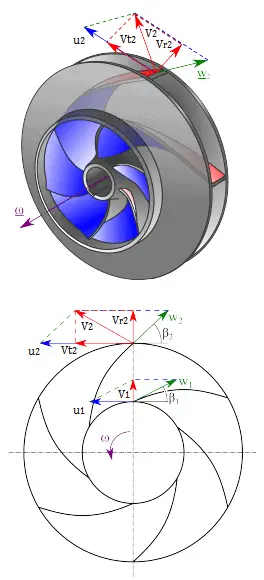
First, we have to calculate the radial velocity of the flow at the outlet. From the velocity diagram the radial velocity is equal to (we assume that the flow enters exactly normal to the impeller, so tangential component of velocity is zero):

Vr1 = u1 tan 30° =  ω r1 tan 30° = 2π x (1500/60) x 0.1 x tan 30° = 9.1 m/s

Radial component of flow velocity determines how much the volume flow rate is entering the impeller. So when we know Vr1 at inlet, we can determine the discharge of this pump according to following equation. Here b1 means the blade width of the impeller at inlet.

Q = 2π.r1.b1.Vr1 = 2π x 0.1 x 0.04 x 9.1 = 0.229 m3/s

In order to calculate the water horsepower (Pw) required, we have to determine the outlet tangential flow velocity Vt2, because it has been assumed that the inlet tangential velocity Vt1 is equal to zero.

The outlet radial flow velocity follows from conservation of Q:

Q = 2π.r2.b2.Vr2  ⇒ Vr2 = Q / 2π.r2.b2 = 0.229 / (2π x 0.2 x 0.04) =  4.56 m/s

From the figure (velocity triangle) outlet blade angle, β2,  can be easily represented as follows.

cot β2 = (u2 – Vt2) / Vr2

and therefore the outlet tangential flow velocity Vt2 is:

Vt2 = u2 – Vr2 . cot 20° = ω r2 – Vr2 . cot 20° = 2π x 1500/60 x 0.2 – 4.56 x 2.75 = 31.4 – 12.5 = 18.9 m/s.

The water horsepower required is then:

Pw  = ρ Q u2 Vt2 = 1000 [kg/m3] x 0.229 [m3/s] x 31.4 [m/s] x 18.9 [m/s] = 135900 W = 135.6 kW

and the pump head is:

H ≈ Pw / (ρ g Q) = 135900 / (1000 x 9.81 x 0.229) = 60.5 m
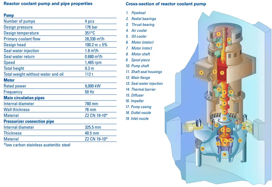
 
NPP Olkiluoto 3 - RCP
Reactor Coolant Pump - parameters
Source: TVO – Olkiluoto 3 NPP
www.tvo.fi/uploads/julkaisut/tiedostot/ydinvoimalayks_OL3_ENG.pdf

System Head
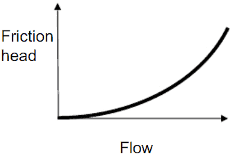
System Head - without static headIn the chapter on head loss, it was determined that both major losses and minor losses in piping systems are proportional to the square of the flow velocity. It is obvious the system head loss must be directly proportional to the square of the volumetric flow rate, because the volumetric flow rate is directly proportional to the flow velocity.

It must be added that the open hydraulic systems contains not only the friction head, but also the elevation head, which must be considered. The elevation head (static head) represents the potential energy of a fluid due to its elevation above a reference level.
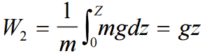
Elevation Head

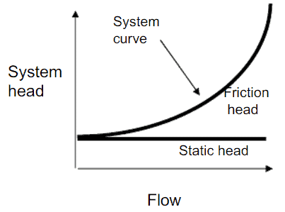
System Head - with static headIn many cases the total head of a system is a combination of elevation head and friction head as shown in the figure.

In nuclear engineering most of hydraulic systems are closed hydraulic loops and these systems only have friction head (no static head).

 
Major Head Loss - Friction Loss

Summary:

  • Head loss of hydraulic system is divided into two main categories:
  • Darcy’s equation can be used to calculate major losses.
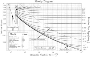
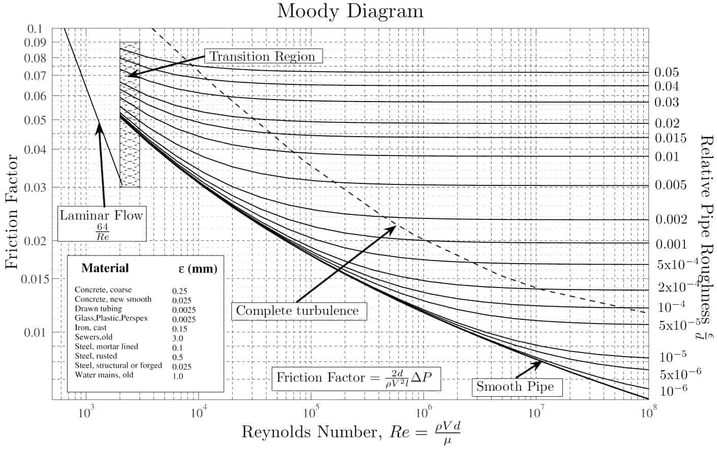
  • The friction factor for fluid flow can be determined using a Moody chart.Moody chart-min
  • The friction factor for laminar flow is independent of roughness of the pipe’s inner surface. f = 64/Re
  • The friction factor for turbulent flow depends strongly on the relative roughness. It is determined by the Colebrook equation. It must be noted, at very large Reynolds numbers, the friction factor is independent of the Reynolds number.

Pump Head – Performance Curve

In fluids dynamics the term pump head is used to measure the kinetic energy which a pump creates. Head is a measurement of the height of the incompressible fluid column the pump could create from the kinetic energy, that the pump gives to the liquid. The head and flow rate determine the performance of a pump, which is graphically shown in the figure as the performance curve or pump characteristic curve. The main reason for using head instead of pressure to determine the performance of a centrifugal pump is that the height of the fluid column is not dependent on the specific gravity (weight) of the liquid, while the pressure from a pump will change. In terms of pressure the pump head (ΔPpump) is difference between system back pressure and the inlet pressure of the pump.

pump head - performace curve - chartThe maximum pump head of a centrifugal pump is mainly determined by the outside diameter of the pump’s impeller and the shaft angular velocity – speed of the rotating shaft. The head will also change as the volumetric flow rate through the pump is increased.

When a centrifugal pump is operating at a constant angular velocity, an increase in the system head (back pressure) on the flowing stream causes a reduction in the volumetric flow rate that the centrifugal pump can maintain.

The relationship between the pump head and the volumetric flow rate (Q), that a centrifugal pump can maintain, is dependent on various physical characteristics of the pump as:

  • the power supplied to the pump
  • the angular velocity of shaft
  • the type and diameter of the impeller

and the used fluid:

  • fluid density
  • fluid viscosity

This relationship is very complicated and its analysis lies in extensive hydraulic testing of certain centrifugal pump. As can be seen from the picture below.

Operating Characteristics of a Hydraulic Loop

When we put together the frictional characteristics (system head) of a hydraulic loop and the performance curve the result will describe the characteristics of entire system (e.g. one loop of primary circuit). The following figure shows typical performance curve for a centrifugal pump related to the system frictional head.

Q-H characteristic diagram of centrifugal pump and of pipeline

Pump head, on the vertical axis, is the difference between system back pressure and the inlet pressure of the pump (ΔPpump). Volumetric flow rate (Q ), on the horizontal axis, is the rate at which fluid is flowing through the pump. As can be seen, the head is approximately constant at low discharge and then drops to zero at Qmax. At low discharge the characteristics can be unstable (with positive slope of pump head). This is undesirable characteristics, because an unstable pump may start to oscillate between the two possible combinations of flow rate and the pipeline can vibrate.

At flow rate Q1 the pump gains more head than consumes the frictional losses, therefore the flow rate through the system will increase. The flow rate will stabilize itself at the point, where the frictional losses intersect the pump characteristics.

In order to characterize the performance of centrifugal pumps, the following terms are defined:

  • Shut-off Head
  • Pump Efficiency
  • Best Efficiency Point – BEP
  • Brake Horsepower
  • Net Positive Suction Head
 
References:
Reactor Physics and Thermal Hydraulics:
  1. J. R. Lamarsh, Introduction to Nuclear Reactor Theory, 2nd ed., Addison-Wesley, Reading, MA (1983).
  2. J. R. Lamarsh, A. J. Baratta, Introduction to Nuclear Engineering, 3d ed., Prentice-Hall, 2001, ISBN: 0-201-82498-1.
  3. W. M. Stacey, Nuclear Reactor Physics, John Wiley & Sons, 2001, ISBN: 0- 471-39127-1.
  4. Glasstone, Sesonske. Nuclear Reactor Engineering: Reactor Systems Engineering, Springer; 4th edition, 1994, ISBN: 978-0412985317
  5. Todreas Neil E., Kazimi Mujid S. Nuclear Systems Volume I: Thermal Hydraulic Fundamentals, Second Edition. CRC Press; 2 edition, 2012, ISBN: 978-0415802871
  6. Zohuri B., McDaniel P. Thermodynamics in Nuclear Power Plant Systems. Springer; 2015, ISBN: 978-3-319-13419-2
  7. Moran Michal J., Shapiro Howard N. Fundamentals of Engineering Thermodynamics, Fifth Edition, John Wiley & Sons, 2006, ISBN: 978-0-470-03037-0
  8. Kleinstreuer C. Modern Fluid Dynamics. Springer, 2010, ISBN 978-1-4020-8670-0.
  9. U.S. Department of Energy, THERMODYNAMICS, HEAT TRANSFER, AND FLUID FLOW. DOE Fundamentals Handbook, Volume 1, 2 and 3. June 1992.
  10. White Frank M., Fluid Mechanics, McGraw-Hill Education, 7th edition, February, 2010, ISBN: 978-0077422417

See also:

Centrifugal Pumps

We hope, this article, Performance Characteristics of Centrifugal Pumps, helps you. If so, give us a like in the sidebar. Main purpose of this website is to help the public to learn some interesting and important information about thermal engineering.

What is System Head – Definition

System head is major head loss of hydraulic system. The system head loss must be directly proportional to the square of the volumetric flow rate. Thermal Engineering

System Head

System Head - without static headIn the chapter on head loss, it was determined that both major losses and minor losses in piping systems are proportional to the square of the flow velocity. It is obvious the system head loss must be directly proportional to the square of the volumetric flow rate, because the volumetric flow rate is directly proportional to the flow velocity.

It must be added that the open hydraulic systems contains not only the friction head, but also the elevation head, which must be considered. The elevation head (static head) represents the potential energy of a fluid due to its elevation above a reference level.
Elevation Head

System Head - with static headIn many cases the total head of a system is a combination of elevation head and friction head as shown in the figure.

In nuclear engineering most of hydraulic systems are closed hydraulic loops and these systems only have friction head (no static head).

 
Major Head Loss - Friction Loss

Summary:

  • Head loss of hydraulic system is divided into two main categories:
  • Darcy’s equation can be used to calculate major losses.
  • The friction factor for fluid flow can be determined using a Moody chart.Moody chart-min
  • The friction factor for laminar flow is independent of roughness of the pipe’s inner surface. f = 64/Re
  • The friction factor for turbulent flow depends strongly on the relative roughness. It is determined by the Colebrook equation. It must be noted, at very large Reynolds numbers, the friction factor is independent of the Reynolds number.
 
References:
Reactor Physics and Thermal Hydraulics:
  1. J. R. Lamarsh, Introduction to Nuclear Reactor Theory, 2nd ed., Addison-Wesley, Reading, MA (1983).
  2. J. R. Lamarsh, A. J. Baratta, Introduction to Nuclear Engineering, 3d ed., Prentice-Hall, 2001, ISBN: 0-201-82498-1.
  3. W. M. Stacey, Nuclear Reactor Physics, John Wiley & Sons, 2001, ISBN: 0- 471-39127-1.
  4. Glasstone, Sesonske. Nuclear Reactor Engineering: Reactor Systems Engineering, Springer; 4th edition, 1994, ISBN: 978-0412985317
  5. Todreas Neil E., Kazimi Mujid S. Nuclear Systems Volume I: Thermal Hydraulic Fundamentals, Second Edition. CRC Press; 2 edition, 2012, ISBN: 978-0415802871
  6. Zohuri B., McDaniel P. Thermodynamics in Nuclear Power Plant Systems. Springer; 2015, ISBN: 978-3-319-13419-2
  7. Moran Michal J., Shapiro Howard N. Fundamentals of Engineering Thermodynamics, Fifth Edition, John Wiley & Sons, 2006, ISBN: 978-0-470-03037-0
  8. Kleinstreuer C. Modern Fluid Dynamics. Springer, 2010, ISBN 978-1-4020-8670-0.
  9. U.S. Department of Energy, THERMODYNAMICS, HEAT TRANSFER, AND FLUID FLOW. DOE Fundamentals Handbook, Volume 1, 2 and 3. June 1992.
  10. White Frank M., Fluid Mechanics, McGraw-Hill Education, 7th edition, February, 2010, ISBN: 978-0077422417

See also:

Centrifugal Pumps

We hope, this article, System Head, helps you. If so, give us a like in the sidebar. Main purpose of this website is to help the public to learn some interesting and important information about thermal engineering.

What is Pump Head – Performance Curve of Centrifugal Pump – Definition

pump head is used to measure the kinetic energy which a centrifugal pump creates. It can be shown in the figure as the performance curve or pump characteristic curve. Thermal Engineering

Pump Head – Performance Curve

In fluids dynamics the term pump head is used to measure the kinetic energy which a pump creates. Head is a measurement of the height of the incompressible fluid column the pump could create from the kinetic energy, that the pump gives to the liquid. The head and flow rate determine the performance of a pump, which is graphically shown in the figure as the performance curve or pump characteristic curve. The main reason for using head instead of pressure to determine the performance of a centrifugal pump is that the height of the fluid column is not dependent on the specific gravity (weight) of the liquid, while the pressure from a pump will change. In terms of pressure the pump head (ΔPpump) is difference between system back pressure and the inlet pressure of the pump.
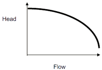
pump head - performace curve - chartThe maximum pump head of a centrifugal pump is mainly determined by the outside diameter of the pump’s impeller and the shaft angular velocity – speed of the rotating shaft. The head will also change as the volumetric flow rate through the pump is increased.

When a centrifugal pump is operating at a constant angular velocity, an increase in the system head (back pressure) on the flowing stream causes a reduction in the volumetric flow rate that the centrifugal pump can maintain.

The relationship between the pump head and the volumetric flow rate (Q), that a centrifugal pump can maintain, is dependent on various physical characteristics of the pump as:

  • the power supplied to the pump
  • the angular velocity of shaft
  • the type and diameter of the impeller

and the used fluid:

  • fluid density
  • fluid viscosity

This relationship is very complicated and its analysis lies in extensive hydraulic testing of certain centrifugal pump. As can be seen from the picture below.

performace curve - brake horsepower

 
Example: Pump Performance Calculation
Pump Head CalculationIn this example, we will see, how to predict
  • the design discharge
  • water horsepower
  • the pump head

of a centrifugal pump. This performance data will be derived from the Euler’s turbomachine equation:

Shaft torque:                         Tshaft    =                                     ρQ(r2Vt2 – r1Vt1)

Water horsepower:             Pw         =     ω . Tshaft        =      ρQ(u2Vt2 – u1Vt1)

Pump head:                            H           =     Pw / ρgQ      =      (u2Vt2 – u1Vt1)/g

Given are the following data for a centrifugal water pump:

  • diameters of the impeller at the inlet and outlet
    • r1 = 10 cm
    • r2 = 20 cm
  • Speed = 1500 rpm (revolutions per minute)
  • the blade angle at inlet β1 = 30°
  • the blade angle at outlet β2 = 20°
  • assume that the blade widths at inlet and outlet are: b1 = b2 = 4 cm.

Solution:

First, we have to calculate the radial velocity of the flow at the outlet. From the velocity diagram the radial velocity is equal to (we assume that the flow enters exactly normal to the impeller, so tangential component of velocity is zero):

Vr1 = u1 tan 30° =  ω r1 tan 30° = 2π x (1500/60) x 0.1 x tan 30° = 9.1 m/s

Radial component of flow velocity determines how much the volume flow rate is entering the impeller. So when we know Vr1 at inlet, we can determine the discharge of this pump according to following equation. Here b1 means the blade width of the impeller at inlet.

Q = 2π.r1.b1.Vr1 = 2π x 0.1 x 0.04 x 9.1 = 0.229 m3/s

In order to calculate the water horsepower (Pw) required, we have to determine the outlet tangential flow velocity Vt2, because it has been assumed that the inlet tangential velocity Vt1 is equal to zero.

The outlet radial flow velocity follows from conservation of Q:

Q = 2π.r2.b2.Vr2  ⇒ Vr2 = Q / 2π.r2.b2 = 0.229 / (2π x 0.2 x 0.04) =  4.56 m/s

From the figure (velocity triangle) outlet blade angle, β2,  can be easily represented as follows.

cot β2 = (u2 – Vt2) / Vr2

and therefore the outlet tangential flow velocity Vt2 is:

Vt2 = u2 – Vr2 . cot 20° = ω r2 – Vr2 . cot 20° = 2π x 1500/60 x 0.2 – 4.56 x 2.75 = 31.4 – 12.5 = 18.9 m/s.

The water horsepower required is then:

Pw  = ρ Q u2 Vt2 = 1000 [kg/m3] x 0.229 [m3/s] x 31.4 [m/s] x 18.9 [m/s] = 135900 W = 135.6 kW

and the pump head is:

H ≈ Pw / (ρ g Q) = 135900 / (1000 x 9.81 x 0.229) = 60.5 m

The Affinity Laws
The centrifugal pump is a very capable and flexible machine. It is not necessary to design specific pump for each specific system. The performance of centrifugal pump can be changed by the change in impeller diameter or its rotational speed. The affinity laws, or the pump laws, state how such changes influence the performance of the pump. These laws are summarized in the following points.

• The flow rate or capacity is directly proportional to the pump speed: double the speed / double the flow.

Q ∝ n

• The pump head is directly proportional to the square of the pump speed: double the speed/multiply the pressure by four.

Hp ∝ n2

• The power required by the pump motor is directly proportional to the cube of the pump speed: double the speed/multiply the power by eight.

P ∝ n3

These principles apply regardless of the direction of the change in speed or in impeller diameter. It must be noted the Affinity laws give results that are approximate. There is a discrepancy between the real hydraulic values and calculated. This discrepancy is due to hydraulic efficiency changes.

Series Operation of Centrifugal Pumps (Booster)

In order to increase the volumetric flow rate in a system or to compensate for large major or minor losses, centrifugal pumps are often used in parallel or in series.

Series operation of centrifugal pumps is used to overcome large system head loss, or to gain large pressure increase when liquid is injected into very high pressure system (e.g. High Pressure Safety Injection Systems in PWRs, where multi-stage pumps are used).

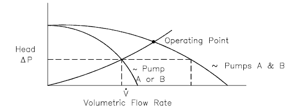
When a centrifugal pump is operated in a closed loop, the resulting discharge pressure will be simply the sum of the suction pressure and the pressure normally developed by the pump when operating at zero suction pressure. Therefore it is well suited for use as a booster pump when operated in series. The head produced by two or more pumps is equal to the sum of the individual heads. The volumetric flow rate from the inlet of the first pump to the outlet of the second remains the same. In practical application the multi-stage pumps (multiple impeller pump) are build in order to reach higher pump head.

Series operation of centrifugal pumps

Parallel Operation of Centrifugal Pumps

In order to increase the volumetric flow rate in a system or to compensate for large major or minor losses, centrifugal pumps are often used in parallel or in series.

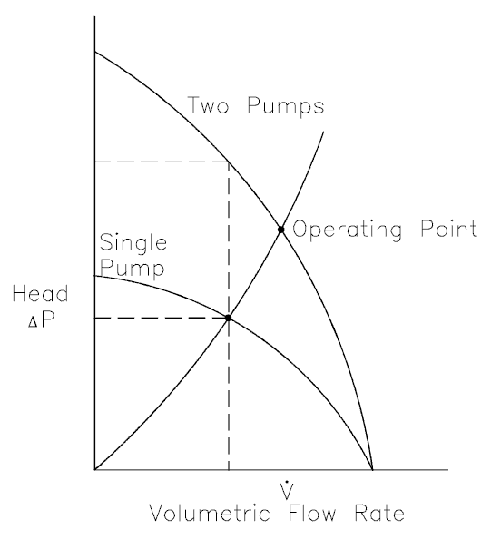
Parallel operation of centrifugal pumps is used to increase flow rate through the system. Pumps operating in parallel take their suction from a common header and discharge into a common discharge. While head changes only slightly, flow is almost doubled at any given point. It must be noted the volumetric flow rate is actually less than twice the flow rate achieved by using a single pump. This is caused by a greater system head loss resulting from higher flow rate.

parallel operation of centrifugal pumps

 
References:
Reactor Physics and Thermal Hydraulics:
  1. J. R. Lamarsh, Introduction to Nuclear Reactor Theory, 2nd ed., Addison-Wesley, Reading, MA (1983).
  2. J. R. Lamarsh, A. J. Baratta, Introduction to Nuclear Engineering, 3d ed., Prentice-Hall, 2001, ISBN: 0-201-82498-1.
  3. W. M. Stacey, Nuclear Reactor Physics, John Wiley & Sons, 2001, ISBN: 0- 471-39127-1.
  4. Glasstone, Sesonske. Nuclear Reactor Engineering: Reactor Systems Engineering, Springer; 4th edition, 1994, ISBN: 978-0412985317
  5. Todreas Neil E., Kazimi Mujid S. Nuclear Systems Volume I: Thermal Hydraulic Fundamentals, Second Edition. CRC Press; 2 edition, 2012, ISBN: 978-0415802871
  6. Zohuri B., McDaniel P. Thermodynamics in Nuclear Power Plant Systems. Springer; 2015, ISBN: 978-3-319-13419-2
  7. Moran Michal J., Shapiro Howard N. Fundamentals of Engineering Thermodynamics, Fifth Edition, John Wiley & Sons, 2006, ISBN: 978-0-470-03037-0
  8. Kleinstreuer C. Modern Fluid Dynamics. Springer, 2010, ISBN 978-1-4020-8670-0.
  9. U.S. Department of Energy, THERMODYNAMICS, HEAT TRANSFER, AND FLUID FLOW. DOE Fundamentals Handbook, Volume 1, 2 and 3. June 1992.
  10. White Frank M., Fluid Mechanics, McGraw-Hill Education, 7th edition, February, 2010, ISBN: 978-0077422417

See also:

Centrifugal Pumps

We hope, this article, Pump Head – Performance Curve of Centrifugal Pump, helps you. If so, give us a like in the sidebar. Main purpose of this website is to help the public to learn some interesting and important information about thermal engineering.

What is Operating Characteristics of a Hydraulic Loop – Definition

When we put together the frictional characteristics (system head) of a hydraulic loop and the performance curve the result will describe the characteristics of entire system. Thermal Engineering

Operating Characteristics of a Hydraulic Loop

When we put together the frictional characteristics (system head) of a hydraulic loop and the performance curve the result will describe the characteristics of entire system (e.g. one loop of primary circuit). The following figure shows typical performance curve for a centrifugal pump related to the system frictional head.
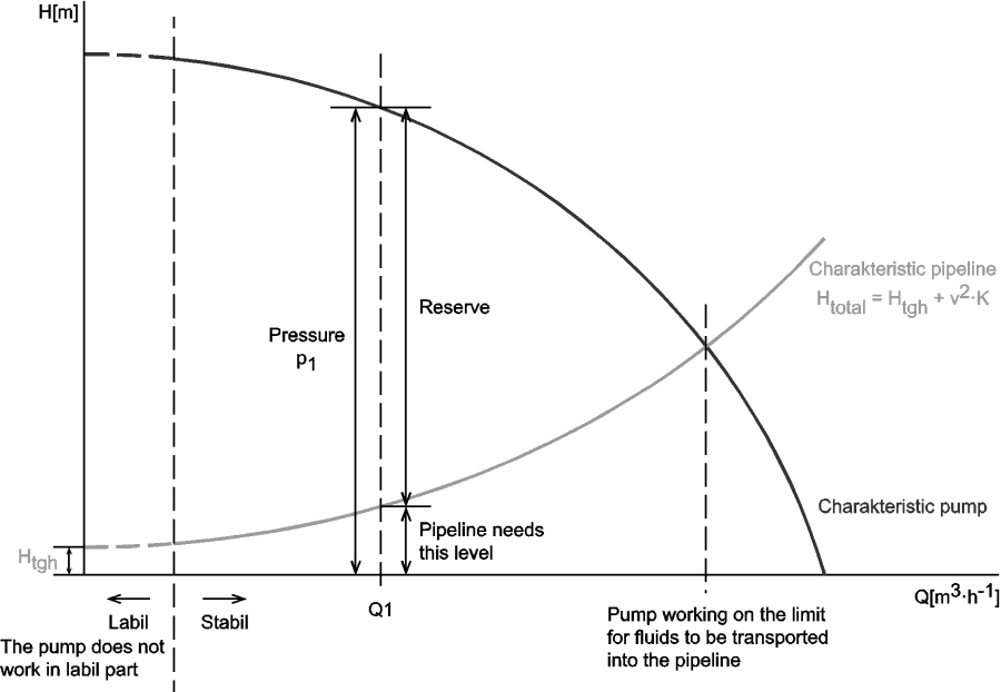
Q-H characteristic diagram of centrifugal pump and of pipeline

Pump head, on the vertical axis, is the difference between system back pressure and the inlet pressure of the pump (ΔPpump). Volumetric flow rate (Q ), on the horizontal axis, is the rate at which fluid is flowing through the pump. As can be seen, the head is approximately constant at low discharge and then drops to zero at Qmax. At low discharge the characteristics can be unstable (with positive slope of pump head). This is undesirable characteristics, because an unstable pump may start to oscillate between the two possible combinations of flow rate and the pipeline can vibrate.

At flow rate Q1 the pump gains more head than consumes the frictional losses, therefore the flow rate through the system will increase. The flow rate will stabilize itself at the point, where the frictional losses intersect the pump characteristics.

 
References:
Reactor Physics and Thermal Hydraulics:
  1. J. R. Lamarsh, Introduction to Nuclear Reactor Theory, 2nd ed., Addison-Wesley, Reading, MA (1983).
  2. J. R. Lamarsh, A. J. Baratta, Introduction to Nuclear Engineering, 3d ed., Prentice-Hall, 2001, ISBN: 0-201-82498-1.
  3. W. M. Stacey, Nuclear Reactor Physics, John Wiley & Sons, 2001, ISBN: 0- 471-39127-1.
  4. Glasstone, Sesonske. Nuclear Reactor Engineering: Reactor Systems Engineering, Springer; 4th edition, 1994, ISBN: 978-0412985317
  5. Todreas Neil E., Kazimi Mujid S. Nuclear Systems Volume I: Thermal Hydraulic Fundamentals, Second Edition. CRC Press; 2 edition, 2012, ISBN: 978-0415802871
  6. Zohuri B., McDaniel P. Thermodynamics in Nuclear Power Plant Systems. Springer; 2015, ISBN: 978-3-319-13419-2
  7. Moran Michal J., Shapiro Howard N. Fundamentals of Engineering Thermodynamics, Fifth Edition, John Wiley & Sons, 2006, ISBN: 978-0-470-03037-0
  8. Kleinstreuer C. Modern Fluid Dynamics. Springer, 2010, ISBN 978-1-4020-8670-0.
  9. U.S. Department of Energy, THERMODYNAMICS, HEAT TRANSFER, AND FLUID FLOW. DOE Fundamentals Handbook, Volume 1, 2 and 3. June 1992.
  10. White Frank M., Fluid Mechanics, McGraw-Hill Education, 7th edition, February, 2010, ISBN: 978-0077422417

See also:

Centrifugal Pumps

We hope, this article, Operating Characteristics of a Hydraulic Loop, helps you. If so, give us a like in the sidebar. Main purpose of this website is to help the public to learn some interesting and important information about thermal engineering.
What is Shut-off Head – Definition

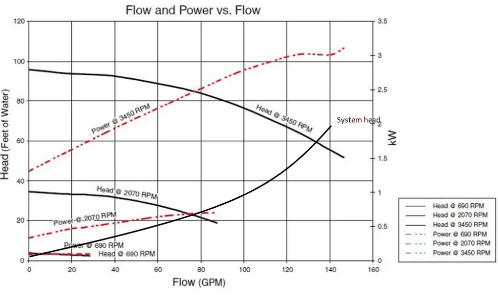
In the performance curve for a pump the shut-off head is the point on the graph where the flow rate is zero. Shut-off head is the vertical lift in height – usually measured in meters of water column

Shut-off Head

In the performance curve for a centrifugal pump the shut-off head is the point on the graph where the flow rate is zero. Shut-off head is the vertical lift in height – usually measured in meters of water column, at which a pump can no longer exert enough pressure to move water.

performace curve - brake horsepower

 
References:
Reactor Physics and Thermal Hydraulics:
  1. J. R. Lamarsh, Introduction to Nuclear Reactor Theory, 2nd ed., Addison-Wesley, Reading, MA (1983).
  2. J. R. Lamarsh, A. J. Baratta, Introduction to Nuclear Engineering, 3d ed., Prentice-Hall, 2001, ISBN: 0-201-82498-1.
  3. W. M. Stacey, Nuclear Reactor Physics, John Wiley & Sons, 2001, ISBN: 0- 471-39127-1.
  4. Glasstone, Sesonske. Nuclear Reactor Engineering: Reactor Systems Engineering, Springer; 4th edition, 1994, ISBN: 978-0412985317
  5. Todreas Neil E., Kazimi Mujid S. Nuclear Systems Volume I: Thermal Hydraulic Fundamentals, Second Edition. CRC Press; 2 edition, 2012, ISBN: 978-0415802871
  6. Zohuri B., McDaniel P. Thermodynamics in Nuclear Power Plant Systems. Springer; 2015, ISBN: 978-3-319-13419-2
  7. Moran Michal J., Shapiro Howard N. Fundamentals of Engineering Thermodynamics, Fifth Edition, John Wiley & Sons, 2006, ISBN: 978-0-470-03037-0
  8. Kleinstreuer C. Modern Fluid Dynamics. Springer, 2010, ISBN 978-1-4020-8670-0.
  9. U.S. Department of Energy, THERMODYNAMICS, HEAT TRANSFER, AND FLUID FLOW. DOE Fundamentals Handbook, Volume 1, 2 and 3. June 1992.
  10. White Frank M., Fluid Mechanics, McGraw-Hill Education, 7th edition, February, 2010, ISBN: 978-0077422417

See also:

Centrifugal Pumps

We hope, this article, Shut-off Head, helps you. If so, give us a like in the sidebar. Main purpose of this website is to help the public to learn some interesting and important information about thermal engineering.
What is Pump Efficiency – Definition

Pump efficiency is the ratio of the water horsepower delivered by the pump and the brake horsepower delivered to the pump shaft. Pump Efficiency. Thermal Engineering

Pump Efficiency

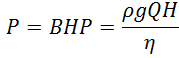
Pump efficiency is the ratio of the water horsepower delivered by a centrifugal pump and the brake horsepower delivered to the pump shaft. When selecting a pump, a key concern is optimizing pumping efficiency. The energy usage in a pumping installation is determined by the flow required, the height lifted and the length and friction characteristics of the pipeline. The power required to drive a pump is defined simply using SI units by:

pump efficiency

where:

  • P is the input power required (W)
  • BHP is the brake horsepower
  • ρ is the fluid density (kg/m3 )
  • g is the standard acceleration of gravity (9.81 m/s2 )
  • H is the net pump head added to the flow (m)
  • Q is the flow rate (m3 /s)
  • η is the efficiency of the pump
 
References:
Reactor Physics and Thermal Hydraulics:
  1. J. R. Lamarsh, Introduction to Nuclear Reactor Theory, 2nd ed., Addison-Wesley, Reading, MA (1983).
  2. J. R. Lamarsh, A. J. Baratta, Introduction to Nuclear Engineering, 3d ed., Prentice-Hall, 2001, ISBN: 0-201-82498-1.
  3. W. M. Stacey, Nuclear Reactor Physics, John Wiley & Sons, 2001, ISBN: 0- 471-39127-1.
  4. Glasstone, Sesonske. Nuclear Reactor Engineering: Reactor Systems Engineering, Springer; 4th edition, 1994, ISBN: 978-0412985317
  5. Todreas Neil E., Kazimi Mujid S. Nuclear Systems Volume I: Thermal Hydraulic Fundamentals, Second Edition. CRC Press; 2 edition, 2012, ISBN: 978-0415802871
  6. Zohuri B., McDaniel P. Thermodynamics in Nuclear Power Plant Systems. Springer; 2015, ISBN: 978-3-319-13419-2
  7. Moran Michal J., Shapiro Howard N. Fundamentals of Engineering Thermodynamics, Fifth Edition, John Wiley & Sons, 2006, ISBN: 978-0-470-03037-0
  8. Kleinstreuer C. Modern Fluid Dynamics. Springer, 2010, ISBN 978-1-4020-8670-0.
  9. U.S. Department of Energy, THERMODYNAMICS, HEAT TRANSFER, AND FLUID FLOW. DOE Fundamentals Handbook, Volume 1, 2 and 3. June 1992.
  10. White Frank M., Fluid Mechanics, McGraw-Hill Education, 7th edition, February, 2010, ISBN: 978-0077422417

See also:

Centrifugal Pumps

We hope, this article, Pump Efficiency, helps you. If so, give us a like in the sidebar. Main purpose of this website is to help the public to learn some interesting and important information about thermal engineering.
What is Best Efficiency Point – BEP – Definition

The best efficiency point (BEP) is the point of highest efficiency of the pump. It is an internal characteristic of each pump and must be provided by pump manufacturer. Thermal Engineering

Pump Efficiency

Pump efficiency is the ratio of the water horsepower delivered by the pump and the brake horsepower delivered to the pump shaft. When selecting a pump, a key concern is optimizing pumping efficiency. The energy usage in a pumping installation is determined by the flow required, the height lifted and the length and friction characteristics of the pipeline. The power required to drive a pump is defined simply using SI units by:

pump efficiency

where:

  • P is the input power required (W)
  • BHP is the brake horsepower
  • ρ is the fluid density (kg/m3 )
  • g is the standard acceleration of gravity (9.81 m/s2 )
  • H is the net pump head added to the flow (m)
  • Q is the flow rate (m3 /s)
  • η is the efficiency of the pump

Best Efficiency Point

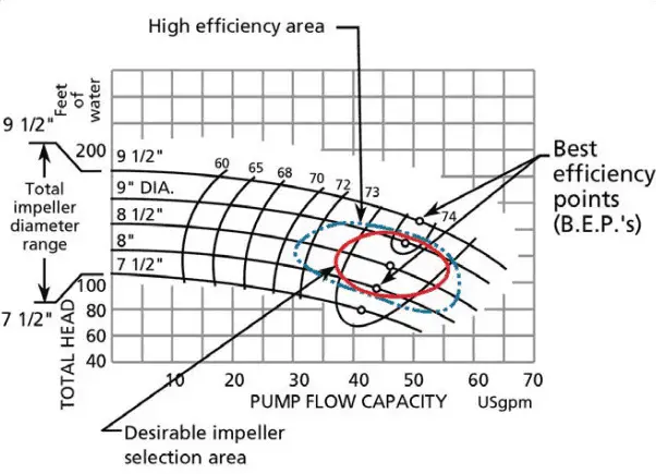
best efficiency point (BEP) - centrifugal pumpThe best efficiency point (BEP) is the point of highest efficiency of the pump. It is an internal characteristic of each centrifugal pump. It must be noted, any pump does not completely convert kinetic energy to pressure energy. Some of the energy is always internal or external lost.

The internal losses are caused by fluid friction in the impeller due to rapid change in flow direction and change in velocities throughout the pump. The external losses are caused by mechanical losses in seals and bearings. All points to the right or left of the BEP have a lower efficiency. Pumps should be sized as close as possible to its best efficiency point or flow rate. This not only makes the pump more efficient but also improves the reliability of the pump. Note that total efficiency is never realized because of mechanical and hydraulic losses incurred in the pump.

Impeller design is the most significant factor for determining the BEP of a pump because it determines how efficiently power (brake horsepower or BHP) is transmitted to the liquid being pumped. A properly designed impeller optimizes flow while minimizing turbulence and maximizing efficiency.

 
References:
Reactor Physics and Thermal Hydraulics:
  1. J. R. Lamarsh, Introduction to Nuclear Reactor Theory, 2nd ed., Addison-Wesley, Reading, MA (1983).
  2. J. R. Lamarsh, A. J. Baratta, Introduction to Nuclear Engineering, 3d ed., Prentice-Hall, 2001, ISBN: 0-201-82498-1.
  3. W. M. Stacey, Nuclear Reactor Physics, John Wiley & Sons, 2001, ISBN: 0- 471-39127-1.
  4. Glasstone, Sesonske. Nuclear Reactor Engineering: Reactor Systems Engineering, Springer; 4th edition, 1994, ISBN: 978-0412985317
  5. Todreas Neil E., Kazimi Mujid S. Nuclear Systems Volume I: Thermal Hydraulic Fundamentals, Second Edition. CRC Press; 2 edition, 2012, ISBN: 978-0415802871
  6. Zohuri B., McDaniel P. Thermodynamics in Nuclear Power Plant Systems. Springer; 2015, ISBN: 978-3-319-13419-2
  7. Moran Michal J., Shapiro Howard N. Fundamentals of Engineering Thermodynamics, Fifth Edition, John Wiley & Sons, 2006, ISBN: 978-0-470-03037-0
  8. Kleinstreuer C. Modern Fluid Dynamics. Springer, 2010, ISBN 978-1-4020-8670-0.
  9. U.S. Department of Energy, THERMODYNAMICS, HEAT TRANSFER, AND FLUID FLOW. DOE Fundamentals Handbook, Volume 1, 2 and 3. June 1992.
  10. White Frank M., Fluid Mechanics, McGraw-Hill Education, 7th edition, February, 2010, ISBN: 978-0077422417

See also:

Centrifugal Pumps

We hope, this article, Best Efficiency Point – BEP, helps you. If so, give us a like in the sidebar. Main purpose of this website is to help the public to learn some interesting and important information about thermal engineering.
What is Brake Horsepower – Definition

The power required to drive the pump is usually known as the brake horsepower. It can be expressed in terms of the water horsepower divided by efficiency. Thermal Engineering

Brake Horsepower

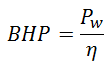
The power required to drive a centrifugal pump is usually known as the brake horsepower. It can be expressed in terms of the water horsepower divided by efficiency.

brake horsepower

In the metric system kilowatts (kW) are used. Due to hydraulic, mechanical and volumetric losses in a pump the actual or water horsepower available for work on the fluid is less than the total horsepower supplied.

Pump Efficiency

Pump efficiency is the ratio of the water horsepower delivered by the pump and the brake horsepower delivered to the pump shaft. When selecting a pump, a key concern is optimizingpumping efficiency. The energy usage in a pumping installation is determined by the flow required, the height lifted and the length and friction characteristics of the pipeline. The power required to drive a pump is defined simply using SI units by:

pump efficiency

where:

  • P is the input power required (W)
  • BHP is the brake horsepower
  • ρ is the fluid density (kg/m3 )
  • g is the standard acceleration of gravity (9.81 m/s2 )
  • H is the net pump head added to the flow (m)
  • Q is the flow rate (m3 /s)
  • η is the efficiency of the pump

performace curve - brake horsepower

 
References:
Reactor Physics and Thermal Hydraulics:
  1. J. R. Lamarsh, Introduction to Nuclear Reactor Theory, 2nd ed., Addison-Wesley, Reading, MA (1983).
  2. J. R. Lamarsh, A. J. Baratta, Introduction to Nuclear Engineering, 3d ed., Prentice-Hall, 2001, ISBN: 0-201-82498-1.
  3. W. M. Stacey, Nuclear Reactor Physics, John Wiley & Sons, 2001, ISBN: 0- 471-39127-1.
  4. Glasstone, Sesonske. Nuclear Reactor Engineering: Reactor Systems Engineering, Springer; 4th edition, 1994, ISBN: 978-0412985317
  5. Todreas Neil E., Kazimi Mujid S. Nuclear Systems Volume I: Thermal Hydraulic Fundamentals, Second Edition. CRC Press; 2 edition, 2012, ISBN: 978-0415802871
  6. Zohuri B., McDaniel P. Thermodynamics in Nuclear Power Plant Systems. Springer; 2015, ISBN: 978-3-319-13419-2
  7. Moran Michal J., Shapiro Howard N. Fundamentals of Engineering Thermodynamics, Fifth Edition, John Wiley & Sons, 2006, ISBN: 978-0-470-03037-0
  8. Kleinstreuer C. Modern Fluid Dynamics. Springer, 2010, ISBN 978-1-4020-8670-0.
  9. U.S. Department of Energy, THERMODYNAMICS, HEAT TRANSFER, AND FLUID FLOW. DOE Fundamentals Handbook, Volume 1, 2 and 3. June 1992.
  10. White Frank M., Fluid Mechanics, McGraw-Hill Education, 7th edition, February, 2010, ISBN: 978-0077422417

See also:

Centrifugal Pumps

We hope, this article, Brake Horsepower, helps you. If so, give us a like in the sidebar. Main purpose of this website is to help the public to learn some interesting and important information about thermal engineering.
What is Net Positive Suction Head – Definition

Net Positive Suction Head or NPSH for pumps can be defined as the difference between the suction pressure and the saturation pressure of the fluid. Thermal Engineering

Net Positive Suction Head


Net Positive Suction HeadNet Positive Suction Head
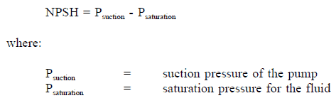
or NPSH for pumps can be defined as the difference between the suction pressure and the saturation pressure of the fluid, expressed in terms of height of liquid column. NPSH is used to measure how close a fluid is to saturated conditions. Lowering the pressure at the suction side can induce cavitation. If cavitation occurs, the violent collapse of the cavitation bubble creates a shock wave that can carve material from internal pump components (usually the leading edge of the impeller) and creates noise often described as “pumping gravel”. Additionally, the inevitable increase in vibration can cause other mechanical faults in the pump and associated equipment.

Net Positive Suction Head - definition

In general, there are two suction heads defined in hydraulics:

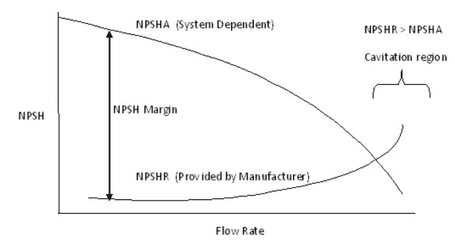
  • NPSH Available (NPSHa): The absolute pressure at the suction port of the pump. NPSHa is a function of water temperature. As the inlet temperature increases NPSHa decreases, because the saturation pressure decreases.
  • NPSH Required (NPSHR): The minimum pressure required at the suction port of the pump to keep the pump from cavitating. NPSHa is not a function of water temperature.

NPSHA is a function of your system and must be calculated, whereas NPSHR is a function of the pump and must be provided by the pump manufacturer. During operation the available NPSH must be maintained at a level greater than the NPSH required by the pump manufacturer. It has been found that cavitation rates increase rapidly with the increase in the volume flow rate. This can be seen from the picture, as volume flow rate increases, NPSH required increases, but the available NPSH decreases.

How to increase NPSH available?

To avoid suction cavitation, NPSH available must be increased as much as possible. The only way to increase NPSH available is to increase the pressure at the pump inlet:

  • Lower the pump level
  • Raise the reservoir level
  • Reduction of motor RPM if possible
  • Reduce minor losses upstream of the pump
  • Reduce major losses upstream of the pump
    • Shorten the length of pipe
    • Use a smoother pipe
  • Increase of the diameter of the eye of the impeller
  • Use of a booster pump to feed the principal pump.
 
References:
Reactor Physics and Thermal Hydraulics:
  1. J. R. Lamarsh, Introduction to Nuclear Reactor Theory, 2nd ed., Addison-Wesley, Reading, MA (1983).
  2. J. R. Lamarsh, A. J. Baratta, Introduction to Nuclear Engineering, 3d ed., Prentice-Hall, 2001, ISBN: 0-201-82498-1.
  3. W. M. Stacey, Nuclear Reactor Physics, John Wiley & Sons, 2001, ISBN: 0- 471-39127-1.
  4. Glasstone, Sesonske. Nuclear Reactor Engineering: Reactor Systems Engineering, Springer; 4th edition, 1994, ISBN: 978-0412985317
  5. Todreas Neil E., Kazimi Mujid S. Nuclear Systems Volume I: Thermal Hydraulic Fundamentals, Second Edition. CRC Press; 2 edition, 2012, ISBN: 978-0415802871
  6. Zohuri B., McDaniel P. Thermodynamics in Nuclear Power Plant Systems. Springer; 2015, ISBN: 978-3-319-13419-2
  7. Moran Michal J., Shapiro Howard N. Fundamentals of Engineering Thermodynamics, Fifth Edition, John Wiley & Sons, 2006, ISBN: 978-0-470-03037-0
  8. Kleinstreuer C. Modern Fluid Dynamics. Springer, 2010, ISBN 978-1-4020-8670-0.
  9. U.S. Department of Energy, THERMODYNAMICS, HEAT TRANSFER, AND FLUID FLOW. DOE Fundamentals Handbook, Volume 1, 2 and 3. June 1992.
  10. White Frank M., Fluid Mechanics, McGraw-Hill Education, 7th edition, February, 2010, ISBN: 978-0077422417

See also:

Centrifugal Pumps

We hope, this article, Net Positive Suction Head, helps you. If so, give us a like in the sidebar. Main purpose of this website is to help the public to learn some interesting and important information about thermal engineering.

What is Series Operation of Centrifugal Pumps – Definition

Series operation of centrifugal pumps is used to overcome large system head loss, or to gain large pressure increase when liquid is injected into very high pressure system. Thermal Engineering

Series Operation of Centrifugal Pumps (Booster)

In order to increase the volumetric flow rate in a system or to compensate for large major or minor losses, centrifugal pumps are often used in parallel or in series.

Series operation of centrifugal pumps is used to overcome large system head loss, or to gain large pressure increase when liquid is injected into very high pressure system (e.g. High Pressure Safety Injection Systems in PWRs, where multi-stage pumps are used).

When a centrifugal pump is operated in a closed loop, the resulting discharge pressure will be simply the sum of the suction pressure and the pressure normally developed by the pump when operating at zero suction pressure. Therefore it is well suited for use as a booster pump when operated in series. The head produced by two or more pumps is equal to the sum of the individual heads. The volumetric flow rate from the inlet of the first pump to the outlet of the second remains the same. In practical application the multi-stage pumps (multiple impeller pump) are build in order to reach higher pump head.

Series operation of centrifugal pumps

 
References:
Reactor Physics and Thermal Hydraulics:
  1. J. R. Lamarsh, Introduction to Nuclear Reactor Theory, 2nd ed., Addison-Wesley, Reading, MA (1983).
  2. J. R. Lamarsh, A. J. Baratta, Introduction to Nuclear Engineering, 3d ed., Prentice-Hall, 2001, ISBN: 0-201-82498-1.
  3. W. M. Stacey, Nuclear Reactor Physics, John Wiley & Sons, 2001, ISBN: 0- 471-39127-1.
  4. Glasstone, Sesonske. Nuclear Reactor Engineering: Reactor Systems Engineering, Springer; 4th edition, 1994, ISBN: 978-0412985317
  5. Todreas Neil E., Kazimi Mujid S. Nuclear Systems Volume I: Thermal Hydraulic Fundamentals, Second Edition. CRC Press; 2 edition, 2012, ISBN: 978-0415802871
  6. Zohuri B., McDaniel P. Thermodynamics in Nuclear Power Plant Systems. Springer; 2015, ISBN: 978-3-319-13419-2
  7. Moran Michal J., Shapiro Howard N. Fundamentals of Engineering Thermodynamics, Fifth Edition, John Wiley & Sons, 2006, ISBN: 978-0-470-03037-0
  8. Kleinstreuer C. Modern Fluid Dynamics. Springer, 2010, ISBN 978-1-4020-8670-0.
  9. U.S. Department of Energy, THERMODYNAMICS, HEAT TRANSFER, AND FLUID FLOW. DOE Fundamentals Handbook, Volume 1, 2 and 3. June 1992.
  10. White Frank M., Fluid Mechanics, McGraw-Hill Education, 7th edition, February, 2010, ISBN: 978-0077422417

See also:

Centrifugal Pumps

We hope, this article, Series Operation of Centrifugal Pumps, helps you. If so, give us a like in the sidebar. Main purpose of this website is to help the public to learn some interesting and important information about thermal engineering.