Facebook Instagram Youtube Twitter

Water hammer analysis in piping systems

Learn about water hammer in piping systems, its causes, analysis with the Joukowsky equation, and effective mitigation strategies.
Water hammer analysis in piping systems

Understanding Water Hammer in Piping Systems

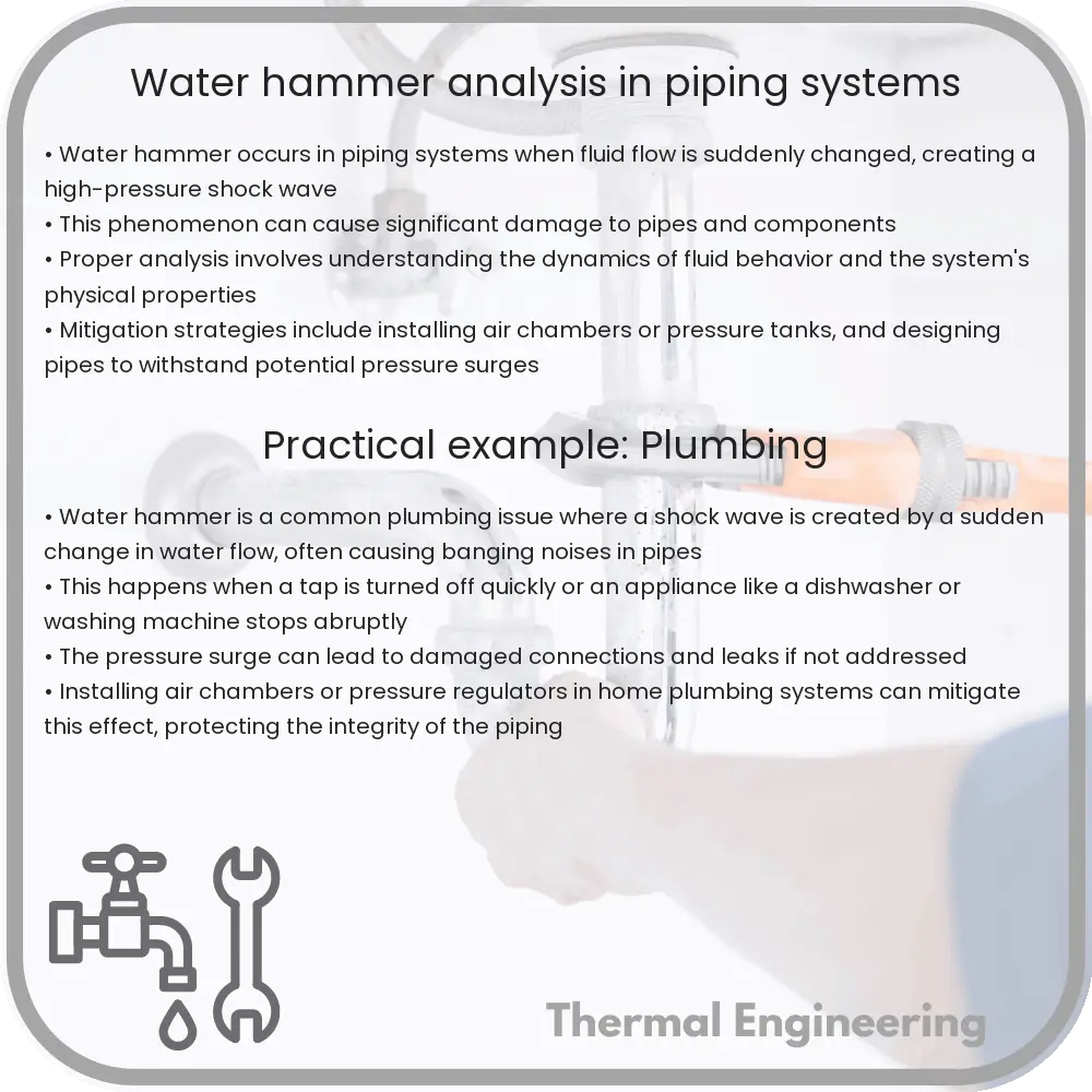
Water hammer, also known as hydraulic shock, is a common phenomenon in piping systems that can lead to significant challenges, including pipe damage and system failure. This article provides an exploration of what water hammer is, why it occurs, and how it can be analyzed and mitigated in engineering.

What is Water Hammer?

Water hammer occurs when a fluid in motion is forced to stop or change direction suddenly. This typically happens in piping systems when valves close abruptly or pumps shut down too quickly. The kinetic energy of the water needs to go somewhere and is converted into pressure, creating a shock wave that travels through the system. The name ‘water hammer’ derives from the banging or hammering sound that often accompanies this sudden rise in pressure.

Causes of Water Hammer

  • Quick-closing valves: Valves that close in less than the time it takes for a pressure wave to travel to the nearest tank or reservoir and back are particularly likely to cause water hammer.
  • Sudden pump failure: If a pump stops abruptly due to power failure or other malfunctions, the fluid momentum can generate high pressure and a shock wave.
  • Direction changes: Sudden changes in pipe direction, such as elbows or bends, can also initiate water hammer, particularly under high flow velocities.

Mathematical Analysis of Water Hammer

The intensity of water hammer can be calculated using the Joukowsky equation:

ΔP = ρ * a * Δv

  • ΔP is the change in pressure
  • ρ (rho) is the density of the fluid
  • a is the speed of the pressure wave in the pipe
  • Δv is the change in the fluid’s velocity

This equation implies that the pressure surge is proportional to the speed of the pressure wave, which depends on the elastic properties of the fluid and the pipe, and the change in velocity of the fluid.

Mitigation Techniques

  • Proper pipe design: Designing piping systems to minimize abrupt changes in direction and ensuring pipes are the correct diameter can help reduce the risk of water hammer.
  • Air chambers or pressure tanks: Installing these can absorb the shock wave generated by halted fluid momentum, lowering the impact of water hammer.
  • Slow-closing valves: Using valves that take longer to close can give the fluid more time to decelerate naturally, reducing the risk of shock waves.
  • Surge tanks: Surge tanks are effective in mitigating water hammer by providing a buffer zone where pressure can be normalized.

Conclusion

Water hammer is a significant issue in piping systems that can lead to damage and failure. By understanding the causes and employing effective mitigation techniques, engineers can design safer and more reliable systems. Analyzing water hammer through models and equations like the Joukowsky equation also allows for precise predictions and better system planning.

Flow optimization in process engineering

Exploring the essentials of flow optimization in process engineering for improved efficiency and reduced operational costs.

Flow optimization in process engineering

Understanding Flow Optimization in Process Engineering

Flow optimization in process engineering is a crucial aspect that focuses on enhancing the efficiency and effectiveness of fluid movement within industrial processes. This practice aims to streamline operations, reduce costs, and improve product quality by meticulously designing and managing the flow paths of liquids and gases. By optimizing flow, companies can achieve higher safety standards, minimize environmental impact, and bolster overall process performance.

Key Principles of Flow Optimization

At its core, flow optimization involves a number of fundamental principles:

  • Laminar vs. Turbulent Flow: Understanding the nature of the flow—whether it is laminar (smooth and orderly) or turbulent (chaotic and swirling)—is essential. Laminar flow generally occurs at lower velocities and higher viscosities and is often more desirable in process systems as it minimizes energy losses and wear.
  • Reynolds Number: This dimensionless quantity helps predict flow patterns in different fluid flow situations. The Reynolds number (Re) is calculated as Re = (ρ * v * L) / μ, where ρ is the fluid density, v is the flow velocity, L is a characteristic linear dimension (like pipe diameter), and μ is the dynamic viscosity of the fluid. Generally, a Re below 2000 indicates laminar flow, while a Re above 4000 suggests turbulent flow.
  • Pressure Drop and Energy Loss: Minimizing pressure drops and associated energy losses is critical in flow optimization. Engineers strive to design systems that maintain sufficient flow rates while using the least amount of energy and maintaining pressure stability.

Methods Used in Flow Optimization

To achieve optimal flow, multiple methods and tools are employed in process engineering:

  1. Computational Fluid Dynamics (CFD): CFD is a powerful computational tool used to simulate fluid flow using numerical analysis and data structures. It helps predict flow patterns, temperature distribution, and possible points of inefficiency or failure without needing physical prototypes.
  2. Piping and Instrumentation Design: Effective layout and sizing of pipes, valves, and fittings are paramount. Engineers use specific design criteria and standards to ensure smooth flow, easy maintenance, and operational safety.
  3. Use of Optimal Materials: Selecting appropriate materials for pipes and components that minimize friction and resist wear, corrosion, and chemical attacks is crucial for long-term system reliability.

Real-World Applications

Flow optimization finds applications across a breadth of industrial settings:

  • Chemical Manufacturing: Optimizing the flow of chemicals through reactors, columns, and transfer lines, ensuring precise control over reaction times and product quality.
  • Oil and Gas: In refineries and pipelines where the efficient, safe, and economical transport of oil and gas is vital.
  • Water Treatment: Ensuring that water flows through filtration systems efficiently for maximum purification with minimal energy usage.

In conclusion, flow optimization in process engineering plays a pivotal role in enhancing industrial operations across various sectors. By leveraging advanced tools like CFD, adhering to meticulous design standards, and selecting optimal materials, engineers can achieve remarkable improvements in system performance, sustainability, and cost-effectiveness.

Hydraulics of dam spillways

Learn about the hydraulics of dam spillways, their design, types, and role in managing water flow and ensuring dam safety.

Hydraulics of dam spillways

Understanding the Hydraulics of Dam Spillways

Spillways are an essential component of dam engineering, ensuring that the dam can safely pass excess water from the reservoir downstream without causing damage to the structure. The design and operation of spillways involve complex hydraulic principles aimed at controlling water flow efficiently and safely. In this article, we explore the fundamentals of spillway hydraulics and their critical role in dam safety and water management.

Types of Spillways and Their Characteristics

There are several types of dam spillways, each adapted to specific site conditions, hydrological requirements, and economic considerations. The most common types include:

  • Ogee Spillway: Shaped like an ‘S’ in profile, this type of spillway is designed to utilize the principles of hydraulic jump to dissipate energy and reduce downstream erosion.
  • Chute Spillway: This kind of spillway features a steeply sloping channel that directs water from the reservoir to the river downstream. It often incorporates energy dissipators at the end to manage high flow velocities.
  • Side Channel Spillway: Used in narrow valleys where there is limited space at the crest, side channel spillways transport water from the reservoir along the side of the dam to a lower elevation.
  • Shaft Spillway: Also known as a morning glory or bell-mouth spillway, this circular structure operates much like a giant funnel. Water spills over the lip and is conducted down a shaft and tunnel drilled through the dam or its foundation.

Hydraulic Principles of Spillway Design

The design of efficient and safe spillways uses fundamental fluid dynamics principles, including energy conservation, flow rates, and pressure dynamics. Critical considerations include:

  • Hydraulic Loads: Calculations must accurately predict the maximum potential hydrological load to ensure the spillway can handle extreme conditions.
  • Flow Over Spillway: Engineers use the equation Q = CL * L * H1.5, where Q is the flow rate, CL is the coefficient of discharge, L is the length of the spillway crest, and H is the height of the water head over the crest. Understanding and predicting the behavior under different loading scenarios is crucial.
  • Energy Dissipation: Excessive velocities can cause damage downstream of the spillway. Structures such as baffles, hydraulic jumps, stilling basins, and plunge pools are designed to dissipate kinetic energy.
  • Aeration of Flow: This is crucial to prevent cavitation, a phenomenon where rapid changes in pressure lead to the formation of vapor cavities in a liquid. Cavitation can cause significant damage to concrete surfaces of the spillway.

Safety Considerations in Spillway Design

Safety is paramount in the design and construction of dam spillways. Engineers must ensure that structures can withstand probable maximum flood (PMF) scenarios and consider long-term factors such as potential increases in flow due to climate change. Regular maintenance checks and safety evaluations are critical to ensure the structural integrity and operational reliability of spillways.

To summarize, the hydraulics of dam spillways involves a complex interplay of engineering principles designed to control the movement and energy of water. Effective spillway design is crucial for protecting the structural health of dams and for preventing catastrophic failures, thereby ensuring the safety of downstream communities and ecosystems.

Whether you’re an engineering student, a professional, or simply curious about how these majestic structures manage vast quantities of water, understanding spillway hydraulics provides insights into one of the most important aspects of dam engineering.

Fluid mechanics of painting and coating processes

Learn how fluid mechanics optimizes painting and coating processes, focusing on viscosity, surface tension, and flow patterns for better application.

Fluid mechanics of painting and coating processes

Understanding the Fluid Mechanics of Painting and Coating Processes

Fluid mechanics plays a crucial role in various engineering applications, one of which is in the processes of painting and coating. This field of study focuses on the behavior of fluids (liquids and gases) in motion and at rest, which is pivotal in optimizing and controlling the application of paints and coatings in manufacturing and industrial settings. Here, we explore the principles and dynamics involved in the fluid mechanics of these processes.

Key Concepts in Fluid Mechanics for Painting and Coating

The application of fluid mechanics in painting and coating involves several fundamental concepts:

  • Viscosity: Viscosity is a measure of a fluid’s resistance to gradual deformation by shear or tensile stress. In painting, viscosity affects how paint flows and spreads on surfaces, influencing the ease of application and the quality of the finish.
  • Surface Tension: This refers to the elastic tendency of a fluid surface which makes it acquire the least surface area possible. Surface tension affects the wetting and spreading behavior of paints on different substrates, impacting the final appearance and adhesion.
  • Reynolds Number (Re): This is a dimensionless quantity in fluid mechanics used to predict flow patterns in different fluid flow situations. The Reynolds number can indicate whether the flow will be laminar or turbulent, which is critical for ensuring uniform paint coats without defects.
  • Nozzle Design and Atomization: The design of nozzles in spray painting equipment affects atomization – the breakup of liquid into droplets. Effective atomization is crucial for achieving a uniform thin layer of paint across surfaces.

Mathematical Modeling in Paint Application

Numerous equations and models describe the behavior of fluids in painting and coating processes. Some key equations include:

  • Continuity Equation: This equation, given by ∉(dρ/dt) + ∇∙(ρv) = 0 where ρ is the fluid density and v is the velocity field, helps in understanding the conservation of mass in a flowing fluid as it passes through the nozzle of a spray gun.
  • Navier-Stokes Equations: These equations describe how the velocity field behaves in viscous fluid dynamics. They can predict the flow characteristics of paint under different pressures and velocities, critical for automated painting systems.
  • Bernoulli’s Principle: This principle is fundamental in understanding pressure changes in fluid flows. It is often applied to design spray painting equipment to manage the flow rate and pressure of the paint for optimal application.

Practical Applications and Considerations

Effective application of fluid mechanics in painting and coating processes requires attention to several practical aspects:

  • Precision in Application: Ensuring uniform thickness and optimal drying times necessitates precise control over the fluid dynamics parameters like flow rate, nozzle pressure, and spray pattern.
  • Equipment Maintenance: Regular maintenance of spraying equipment to prevent clogging and wear, which can significantly alter flow patterns and degrade the quality of the application.
  • Environmental Conditions: Temperature and humidity can affect the viscosity and drying rate of paint, thus requiring careful adjustments in application methods based on environmental monitoring.

In conclusion, understanding the fundamentals of fluid mechanics not only enhances the efficiency and quality of painting and coating applications but also drives innovation in the methods and technologies used in these processes. By leveraging these principles, engineers can develop more sophisticated and precise application systems that meet the evolving needs of industries.

Hydraulic jumps and their applications

Learn about hydraulic jumps, a fluid dynamic phenomenon where fast-flowing liquid suddenly shifts to a slower, deeper flow, crucial for efficient water management.

Hydraulic jumps and their applications

Understanding Hydraulic Jumps and Their Applications

A hydraulic jump occurs when a flowing liquid undergoes a sudden transition from a high velocity, low-depth flow to a slower-moving, deeper flow. This phenomenon is often observed in rivers, spillways, and other open channels where water flows at high speeds. Understanding hydraulic jumps is not only fascinating from a fluid dynamics perspective but is also crucial in engineering for controlling and managing water resources efficiently.

How Hydraulic Jumps Occur

Hydraulic jumps typically form when a supercritical flow (where the flow velocity is greater than the wave speed in the water) transitions to a subcritical flow (where the velocity is less than the wave speed). This change can occur due to changes in the channel slope, channel roughness, or downstream obstructions, among other reasons.

The exact behavior and nature of the jump depend highly on the Froude number before the transition. The Froude number (Fr) is defined as:

    Fr = V / (g * h)0.5

where V is the flow velocity, g is the acceleration due to gravity, and h is the water depth. When Fr > 1, the flow is supercritical, and when Fr < 1, it is subcritical.

Applications of Hydraulic Jumps

  • Energy Dissipation: Hydraulic jumps are used in hydraulic structures like spillways and weirs to dissipate the energy of water descending from a dam. This helps to prevent erosion at the base of the structure and stabilize the flow.
  • Mixing and Aeration: The turbulent nature of hydraulic jumps can enhance mixing and aeration in the water, which is beneficial for water treatment processes. It helps in increasing the dissolved oxygen levels, crucial for the aquatic ecosystem and water quality.
  • Flood Control: Hydraulic jumps help in controlling the release rate of water through channels and floodgates, thus managing flood situations more effectively.
  • Sediment Control: They can also be used to trap and settle out sediments, which are transported by high velocity flows. This accumulation can then be cleared as needed to maintain channel capacity.

Scientific and Practical Considerations

When designing structures that utilize hydraulic jumps, engineers must consider several factors to ensure efficiency and safety:

  • Precise Calculation: Accurate predictions of the flow conditions before and after the jump are essential to determine the characteristics of the jump and its impact.
  • Control Structures: Depending on the application, additional control structures might be necessary to enhance the stability and efficacy of the hydraulic jump.
  • Structural Integrity: The infrastructure must be able to withstand the forces generated by the turbulent flows and possible debris carried by the water.

In conclusion, hydraulic jumps are a critical concept in fluid dynamics with extensive practical applications in environmental management and civil engineering. Understanding the mechanics of hydraulic jumps allows engineers to design more effective water handling and management systems, contributing significantly to sustainable infrastructure development.

Aeroelasticity in aircraft wings

Aeroelasticity in aircraft wings explores the interplay between aerodynamic forces, structural elasticity, and inertial impacts, crucial for safe and efficient aircraft design.

Aeroelasticity in aircraft wings

Understanding Aeroelasticity in Aircraft Wings

Aeroelasticity in aircraft wings is a fundamental aspect of aerospace engineering that deals with the interaction between aerodynamic forces, structural elasticity, and inertial effects. This field of study ensures the safety, efficiency, and durability of aircraft structures, particularly the wings, under various aerodynamic loads.

What is Aeroelasticity?

Aeroelasticity is the science of studying the dynamic response of elastic structures subjected to aerodynamic forces. In the context of aircraft wings, it focuses on how these structures deform and react to forces generated during flight, such as lift, drag, and turbulence.

Components of Aeroelastic Phenomena

There are several key phenomena involved in aeroelasticity that affect aircraft wings:

  • Flutter: A dangerous oscillatory phenomenon that can lead to the destruction of aircraft structures. Flutter occurs when the aerodynamic forces align with the natural vibration frequency of the wing, amplifying the oscillations until structural failure occurs.
  • Divergence: Another instability phenomenon where a wing deforms under aerodynamic loads, increasing the angle of attack and leading to a potentially uncontrollable rise in lift and drag, and possible structural failure.
  • Control Reversal: This happens when the deformation of the wing structure under aerodynamic loads causes a reversal in the effectiveness of the control surfaces, such as ailerons.

Equations and Principles

The analysis of aeroelastic effects involves a complex interplay of differential equations from fluid dynamics, solid mechanics, and dynamics. A simplified explanation revolves around the balance between aerodynamic loads, the inertial effects of the structure’s mass, and the structural stiffness.

For example, the critical speed at which flutter occurs can be approximated by:

\[
V_f = \sqrt{\frac{K_s}{\rho * B^*S}}
\]

Where \( V_f \) is the flutter speed, \( K_s \) is the stiffness of the wing, \( \rho \) is the air density, \( B^* \) represents the aerodynamic damping factors, and \( S \) is the surface area of the wing.

Engineering Approaches to Mitigate Aeroelastic Effects

To ensure the structural integrity and optimal performance of aircraft wings, engineers employ various strategies:

  • Material Selection and Design: Utilizing materials with the right stiffness-to-weight ratios and designing wing structures to distribute stresses uniformly.
  • Active and Passive Damping: Incorporating devices that absorb vibrational energy or dynamically adjust the stiffness of the wing during flight.
  • Aerodynamic Tailoring: Modifying the shape of the wing to influence the aerodynamic forces and moments in a manner that mitigates undesirable aeroelastic effects.

Conclusion

Understanding and controlling aeroelastic phenomena in aircraft wings is crucial for the design of safe and reliable aircraft. Advances in computational modelling, materials science, and experimental techniques continue to push the boundaries of what is possible in aerospace engineering, leading to aircraft that are lighter, faster, and more robust against the dynamic forces they encounter in flight.

As technology progresses, the study of aeroelasticity will remain a critical area in the design and operation of not only conventional aircraft but also in emerging technologies such as drones and other unmanned aerial vehicles.

Flow in fractal geometries

Explore how fractal geometries impact flow characteristics in various systems, offering insights into natural and engineered structures.

Flow in fractal geometries

Understanding Flow in Fractal Geometries

When we examine the complexities of flow patterns, especially in systems that defy traditional geometric forms, fractal geometries offer a fascinating area of study. Fractals are irregular, self-similar structures that repeat their shape at different scales, and they are prevalent in nature, from the branching of trees and rivers to the structure of lungs and blood vessels. In engineering, understanding flow in these fractal geometries can lead to innovations in various fields including material sciences, environmental engineering, and medical technologies.

Basics of Fractals

Before diving into flow dynamics, it is essential to understand what a fractal is. A fractal is a complex pattern where similar patterns recur at progressively smaller scales. They are defined by their fractal dimension, which quantifies their complexity as a ratio of the change in detail to the change in scale. This dimensional complexity is why fractals are used to describe irregular shapes and spaces that cannot be easily described by traditional Euclidean geometry.

Flow Characteristics in Fractal Structures

The study of flow within fractal geometries revolves around understanding how fluids or gases behave when they travel through paths that are non-linear and complex. Such flow is characterized by:

  • Irregularity: Unlike traditional cylindrical pipes, fractal geometries can greatly vary in diameter and structure, leading to unpredictable flow patterns.
  • Self-similarity: Flow characteristics in each fractal iteration might mimic overall behavior, making the study both challenging and insightful.
  • Scale dependence: The flow behavior can change with scale due to the variation in the size of the fractal iterations.

Modeling Flow in Fractals

To effectively understand and predict the flow in fractal geometries, scientists and engineers use mathematical models and simulations. The primary challenge is to model the fluid dynamics accurately, which often involves complex algorithms and computational fluid dynamics software. The Navier-Stokes equations, which describe the motion of fluid substances, are typically modified to incorporate the fractal dimensions of the structure in the analysis.

For instance, the laminar flow in a fractal-like branching network can be modeled by a series of equations that consider factors like velocity, pressure, and branch diameter at different iterations:

vn+1 = vn * (dn / dn+1)2

Where:

  • vn and vn+1 are the fluid velocities in consecutive iterations,
  • dn and dn+1 are the diameters of the branches at those iterations.

Applications of Fractal Flow Studies

Understanding the flow in fractal geometries has significant implications in numerous fields:

  1. Environmental Engineering: Fractal-based permeable pavements and drainage systems mimic natural landscapes to manage stormwater more effectively.
  2. Material Science: Designing materials with fractal structures that promote efficient heat exchange and fluid transport.
  3. Medical Engineering: Developing more efficient drug delivery systems and biomedical implants based on naturally occurring fractal structures in biological systems.

In conclusion, the study of flow in fractal geometries not only enhances our understanding of natural systems but also drives innovation across several engineering disciplines. By adopting the principles of fractal geometry, engineers can improve product design and functionality, advancing technology that harmonizes with the complex patterns found in nature itself.

Fluid-thermal interaction in energy storage

Explore the dynamics of fluid flows and heat transfer within energy storage systems to optimize efficiency and performance.

Fluid-thermal interaction in energy storage

Understanding Fluid-Thermal Interaction in Energy Storage

Energy storage systems are crucial for maintaining the balance between energy demand and supply, especially with the increasing reliance on intermittent renewable energy sources like wind and solar power. A critical aspect of enhancing the efficiency and longevity of these systems is understanding the fluid-thermal interactions that occur within them. This interaction is particularly significant in systems such as pumped hydroelectric storage, compressed air energy storage, and thermal energy storage.

What is Fluid-Thermal Interaction?

Fluid-thermal interaction refers to the dynamics between fluid flows and heat transfer within an energy storage system. Efficient energy storage and retrieval depend on the optimal management of these interactions. In engineering terms, this involves understanding how fluids (liquids or gases) and thermal processes (like heating or cooling) influence each other and the overall system performance.

Major Types of Energy Storage Involving Fluid-Thermal Dynamics

  • Pumped Hydroelectric Storage: This involves pumping water to a higher elevation during low-demand periods and releasing it to generate electricity when demand is high. The interaction between the moving water (fluid) and its environment (thermal influences like air temperature) affects the efficiency of energy conversion.
  • Compressed Air Energy Storage (CAES): Air is compressed using surplus energy and stored in underground caverns or tanks. The compression process significantly increases the temperature of the air (thermal effect) which must be managed to optimize storage and energy retrieval efficiency.
  • Thermal Energy Storage: These systems store energy in the form of heat, which could be in the solid, liquid, or gaseous state. The fluid’s properties, such as its specific heat capacity and conductivity, play crucial roles in the overall energy transfer and storage capabilities.

Key Engineering Principles Involved

In engineering fluid-thermal systems for energy storage, several key principles are considered:

  1. Thermodynamics: Understanding the laws of thermodynamics helps in predicting how energy transfers and transformations will occur within the system.
  2. Fluid Mechanics: This involves studying the behavior of the fluid under various flow conditions and forces, important for designing channels, turbines, and other components of energy storage systems.
  3. Heat Transfer: Engineering the systems for optimal heat transfer ensures that thermal energy is effectively stored and can be readily converted back into other forms of energy.

Challenges and Innovations

One of the primary challenges in optimizing fluid-thermal interaction in energy storage is managing the losses that occur during energy conversion processes. Innovations like improving materials for heat resistance and developing more efficient cooling and heating strategies are keys to enhancing system performance.

Moreover, advanced computational models and simulations are increasingly used to predict complex fluid-thermal interactions. These tools help engineers design more effective energy storage systems by allowing them to experiment with different configurations and operating conditions in a virtual environment before actual implementation.

Conclusion

The interplay between fluid dynamics and thermal processes is a fundamental aspect of many energy storage systems. By advancing our understanding and capability to engineer these interactions, it is possible to significantly enhance the efficiency and effectiveness of energy storage solutions. This will be crucial for achieving a sustainable energy future, where energy storage plays a vital role in balancing the grid and enabling the expanded use of renewable energy sources.

Nanofluid flow and heat transfer

Exploring the enhancement of thermal systems through nanofluid flow and heat transfer, leveraging nanoparticles to improve thermal conductivity and heat exchange.

Nanofluid flow and heat transfer

Understanding Nanofluid Flow and Heat Transfer

Nanofluid flow and heat transfer are emerging topics within the field of engineering that offer the potential to significantly enhance the performance of thermal systems. Nanofluids are engineered colloids made of a base fluid, such as water or ethylene glycol, and nanoparticles, which are typically metal or metal oxides, such as copper oxide or aluminum oxide. The inclusion of these nanoparticles enhances the thermal properties of the base fluid, leading to improved heat transfer capabilities.

Properties of Nanofluids

The key to the enhanced properties of nanofluids lies in the unique characteristics of the nanoparticles. These include:

  • High surface area: Nanoparticles have a high surface-to-volume ratio, providing a large interface area for heat exchange.
  • Enhanced thermal conductivity: The thermal conductivity of nanoparticles is generally higher than that of the base fluid, thus improving the overall conductivity of the nanofluid.
  • Stability: Good dispersion stability of nanoparticles within the base fluid is crucial to maintain and enhance heat transfer capabilities over time.

Heat Transfer Mechanisms in Nanofluids

In heat transfer applications, nanofluids can be used in various ways, including in heat exchangers, cooling of electronics, and automotive applications. The primary mechanisms by which nanofluids enhance heat transfer are:

  • Brownian Motion of Nanoparticles: The random motion of nanoparticles helps in the transport and mixing within the fluid, which enhances heat transfer.
  • Increased Effective Thermal Conductivity: Adding nanoparticles increases the effective thermal conductivity of the fluid, which enhances the rate of heat transfer.

Mathematical Description of Nanofluid Flow

Understanding the flow and heat transfer of nanofluids requires a combination of classical fluid mechanics and novel approaches due to the particulate nature of the fluid. One common approach is to modify the classical Navier-Stokes and energy equations to include the effects of nanoparticles. The general form of the equation for conservation of mass, momentum, and energy can be expressed as:

  1. Conservation of mass:

    \(\rho (\frac{\partial u}{\partial x} + \frac{\partial v}{\partial y} + \frac{\partial w}{\partial z}) = 0\)

  2. Conservation of momentum:

    \(\rho (\frac{\partial \vec{u}}{\partial t} + \vec{u} \cdot \nabla \vec{u}) = -\nabla p + \mu \nabla^2 \vec{u} + f_p\)

    Where \(f_p\) represents the forces due to the particles.

  3. Conservation of energy:

    \(\rho c_p (\frac{\partial T}{\partial t} + \vec{u} \cdot \nabla T) = k \nabla^2 T + Q\)

    Here, \(Q\) represents any volumetric heat sources within the flow.

Applications of Nanofluids

Nanofluids have found applications across a range of industries due to their enhanced heat transfer characteristics. Some notable applications include:

  • Electronics Cooling: The efficient cooling capabilities of nanofluids are used in managing heat in high-performance computing and electronic devices.
  • Automotive: Improved heat transfer fluids can enhance the performance and efficiency of automotive cooling systems.
  • Renewable Energy: Nanofluids are used in solar thermal energy systems to improve the efficiency of solar collectors.

In conclusion, nanofluid technology represents a promising frontier in enhancing heat transfer for various engineering applications. Ongoing research focuses on better understanding the behavior of these fluids and leveraging their potential to the fullest.

Future Outlook

Despite the significant potential, challenges remain such as particle aggregation, long-term stability, and cost-effectiveness of nanofluid production. Addressing these challenges is crucial for the widespread adoption and application of nanofluid technology in industry. Continued research and development in this area are essential for optimizing formulations that maintain the stability and enhance both the thermal conductivity and heat transfer properties of nanofluids.

Hydrodynamics of fish swimming

Learn about fish swimming and hydrodynamics, analyzing the forces, fluid dynamics, and applications in technology.

Hydrodynamics of fish swimming

Understanding the Hydrodynamics of Fish Swimming

Fish swimming is an elegant demonstration of nature’s mastery of hydrodynamics, the branch of physics concerned with the properties of fluids in motion. By studying how fish swim, scientists and engineers can uncover principles applicable to various technologies, including bio-inspired robotics, underwater vehicles, and energy-efficient propulsion systems.

How Fish Swim: Basic Mechanics

Fish propel themselves through water primarily using their body and fins. The mechanics involve generating thrust while minimizing resistance from the surrounding water. This balance is crucial for the efficient movement of fish through various aquatic environments.

  • Body Shape: Fish have streamlined bodies that reduce drag, the resisting force caused by motion through a fluid. The tapering shape at both ends allows water to flow smoothly over the body, enabling higher speeds with less energy.
  • Muscle Movement: Fish muscles work in segments, contracting sequentially from head to tail, which creates a wave-like motion along their body. This motion, often referred to as undulatory swimming, pushes water backwards, thereby propelling the fish forward.
  • Fins: Fins serve multiple functions including steering, stability, and propulsion. The tail fin, or caudal fin, is particularly important for the thrust during fast swimming and maneuvering.

Hydrodynamics: Forces and Fluid Dynamics

Understanding the hydrodynamics of fish swimming involves analyzing the forces involved and how they interact with the fluid environment. The key forces are thrust and drag, alongside buoyancy and lift.

  • Thrust: This force propels the fish forward and is generated primarily by the movement of the caudal fin. The action of the fin against the water creates a force in the opposite direction according to Newton’s third law of motion.
  • Drag: As fish swim, they encounter drag force that opposes their motion. Drag includes both skin friction, arising from the viscosity of the water and interaction with the fish’s skin, and form drag, caused by the displacement of water by the fish’s body.
  • Lift: Similar to aerodynamics in air, lift in water can occur due to the hydrodynamic effects on the body and fins of the fish, particularly at higher speeds.
  • Buoyancy: This force acts upwards, counteracting the weight of the fish and is crucial for maintaining depth without expending large amounts of energy in vertical movement.

Mathematical Modeling in Fish Hydrodynamics

To analyze and predict fish swimming patterns, scientists use mathematical models that describe the fluid dynamics involved. The basic equations include the Navier-Stokes equations, which describe the motion of fluid substances:

\[
\rho \left(\frac{\partial \mathbf{v}}{\partial t} + \mathbf{v} \cdot \nabla \mathbf{v}\right) = -\nabla p + \mu \nabla^2 \mathbf{v} + \mathbf{f}
\]

Here, \( \rho \) is the fluid density, \( \mathbf{v} \) represents the velocity field, \( p \) stands for pressure within the fluid, \( \mu \) is the dynamic viscosity, and \( \mathbf{f} \) denotes external forces applied to the fluid. This equation, combined with boundary conditions and fluid properties, helps simulate how fish interact with the surrounding water.

Applications in Engineering and Technology

The study of fish swimming is not just an academic pursuit but has practical applications in engineering and technology. For instance:

  • Autonomous Underwater Vehicles (AUVs): Design principles derived from fish can be used to develop AUVs that are more efficient and capable of agile maneuvers in complex underwater environments.
  • Robotic Fish: Bio-inspired robotics include the development of robotic fish that mimic the swimming mechanisms of real fish, useful in underwater exploration and monitoring.
  • Energy Efficiency: Understanding and applying the principles of fish swimming can lead to the design of propulsion systems that are more energy-efficient and less environmentally invasive.

By exploring the hydrodynamics of fish swimming, both scientists and engineers can better understand fluid dynamics. This knowledge not only advances our grasp of biological mechanisms but also inspires innovative solutions in technology and environmental stewardship.