Spray Foam Insulation
Spray foam insulation is a type of insulation that is sprayed in place through a gun. Spray foam insulation can be blown into walls, onto concrete slabs, on attic surfaces, or under floors to insulate and reduce air leakage. Spray foam can fill even the smallest cavities, creating an effective air barrier. Foam usually expands up to 30-60 times its liquid volume after it is sprayed in place. It provides excellent resistance to air infiltration (unlike batts and blankets, which can leave bypasses and air pockets, and superior to some types of loose-fill). On the other han, the cost of spray foam insulation can be higher compared to traditional insulation and most foams, with the exception of cementitious foams, release toxic fumes when they burn.
There are two types of spray foam insulation:
- Closed-cell foam. Closed-cell foams are better insulators. Their high-density cells are closed and filled with a gas that helps the foam expand to fill the spaces around it. Closed-cell foam is very strong, and structurally reinforces the insulated surface.
- Open-cell foam. Open-cell foam cells are not as dense and are filled with air, which gives the insulation a spongy texture. Open-cell foam is porous, allowing water vapor and liquid water to penetrate the insulation. On the other hand, open-cell foams will allow structural wood to breathe and they are about twice effective as a sound barrier.
Available foam insulation materials include:
- Cementitious
- Phenolic
- Polyisocyanurate
- Polyurethane.
Most are typically made with polyurethane or isocyanate. Cementitious foams are similar and can be applied in a similar manner but do not expand. These foams have higher fire resistance in comparison to polyurethane or isocyanate foams.
Attic Insulation – Roof Insulation
 A very important source of heat loss from a house is through roof and attic. Attic insulation is a thermally insulated, protective interior cladding procedure involving the use of glass or rock wool, polyurethane foam or phenolic foam. It must be noted, there is a difference between insulating a pitched roof and a flat roof, and there is a difference between cold or warm loft insulation. A cold roof insulation requires insulation at joist level to stop heat escaping through the unused roof space. A warm roof is insulated between and under the rafters of the roof itself.
The purpose of roof insulation is to reduce the overall heat transfer coefficient by adding materials with low thermal conductivity. Roof and attic insulation in buildings is an important factor to achieving thermal comfort for its occupants. Roof insulation as well as other types of insulation reduce unwanted heat loss and also reduce unwanted heat gain. They can significantly decrease the energy demands of heating and cooling systems. It must be added, there is no material which can completely prevent heat losses, heat losses can be only minimized.
Example of Insulation – Polyurethane Foam
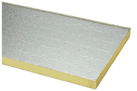
Polyurethane foam (PUR) is a closed cell thermoset polymer. Polyurethane polymers are traditionally and most commonly formed by reacting a di- or poly-isocyanate with a polyol. Polyurethane foam insulation is available in closed-cell and open-cell formulas. Polyurethane foam can be used as cavity wall insulation or as roof insulation, floor insulation, pipe insulation, insulation of industrial installations. Insulating panels made from PUR can be applied to all elements of the building envelope. Another important aspect is that PUR can also be injected into existing cavity walls, by using the existing openings and some extra holes.
Example – Heat Loss through a Wall
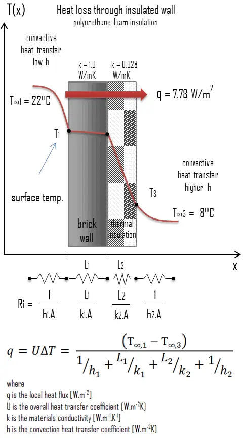
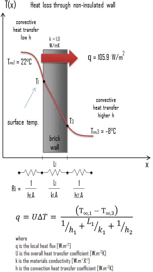 A major source of heat loss from a house is through walls. Calculate the rate of heat flux through a wall 3 m x 10 m in area (A = 30 m2). The wall is 15 cm thick (L1) and it is made of bricks with the thermal conductivity of k1 = 1.0 W/m.K (poor thermal insulator). Assume that, the indoor and the outdoor temperatures are 22°C and -8°C, and the convection heat transfer coefficients on the inner and the outer sides are h1 = 10 W/m2K and h2 = 30 W/m2K, respectively. Note that, these convection coefficients strongly depend especially on ambient and interior conditions (wind, humidity, etc.).
- Calculate the heat flux (heat loss) through this non-insulated wall.
- Now assume thermal insulation on the outer side of this wall. Use polyurethane foam insulation 10 cm thick (L2) with the thermal conductivity of k2 = 0.028 W/m.K and calculate the heat flux (heat loss) through this composite wall.
Solution:
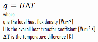
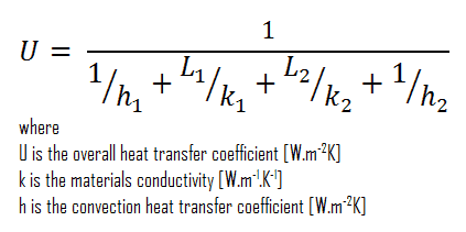
As was written, many of the heat transfer processes involve composite systems and even involve a combination of both conduction and convection. With these composite systems, it is often convenient to work with an overall heat transfer coefficient, known as a U-factor. The U-factor is defined by an expression analogous to Newton’s law of cooling:
The overall heat transfer coefficient is related to the total thermal resistance and depends on the geometry of the problem.
- bare wall
Assuming one-dimensional heat transfer through the plane wall and disregarding radiation, the overall heat transfer coefficient can be calculated as:
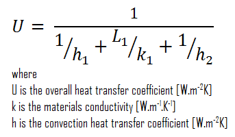
The overall heat transfer coefficient is then:
U = 1 / (1/10 + 0.15/1 + 1/30) = 3.53 W/m2K
The heat flux can be then calculated simply as:
q = 3.53 [W/m2K] x 30 [K] = 105.9 W/m2
The total heat loss through this wall will be:
qloss = q . A = 105.9 [W/m2] x 30 [m2] = 3177W
- composite wall with thermal insulation
Assuming one-dimensional heat transfer through the plane composite wall, no thermal contact resistance and disregarding radiation, the overall heat transfer coefficient can be calculated as:
 The overall heat transfer coefficient is then:
U = 1 / (1/10 + 0.15/1 + 0.1/0.028 + 1/30) = 0.259 W/m2K
The heat flux can be then calculated simply as:
q = 0.259 [W/m2K] x 30 [K] = 7.78 W/m2
The total heat loss through this wall will be:
qloss = q . A = 7.78 [W/m2] x 30 [m2] = 233 W
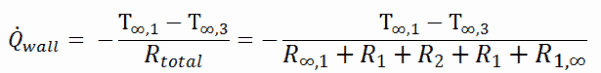
As can be seen, an addition of thermal insulator causes significant decrease in heat losses. It must be added, an addition of next layer of thermal insulator does not cause such high savings. This can be better seen from the thermal resistance method, which can be used to calculate the heat transfer through composite walls. The rate of steady heat transfer between two surfaces is equal to the temperature difference divided by the total thermal resistancebetween those two surfaces.
We hope, this article, Spray Foam Insulation, helps you. If so, give us a like in the sidebar. Main purpose of this website is to help the public to learn some interesting and important information about thermal engineering.