Facebook Instagram Youtube Twitter

Basics of Thermal Power Plants Explained

Learn about the core functions and components of thermal power plants, key players in global electricity production and their environmental impacts.

Basics of Thermal Power Plants Explained

Basics of Thermal Power Plants Explained

Thermal power plants are a cornerstone of the energy industry, producing a significant portion of the world’s electricity. They convert heat energy into electrical energy, predominantly by burning fossil fuels like coal, natural gas, or oil. This article explores the fundamental principles behind thermal power plants and their operation.

How Thermal Power Plants Work

The basic operation of a thermal power plant involves four main steps: heating, steam production, electricity generation, and cooling.

  1. Heating: The fuel (typically coal, oil, or natural gas) is burned in a large boiler to heat water. The combustion produces a large amount of heat, which turns water into steam.
  2. Steam Production: The intense heat from burning fuel converts water in the boiler into high-pressure steam. This steam is then directed to a turbine at high speed.
  3. Electricity Generation: The high-pressure steam turns the blades of a steam turbine, which is connected to a generator. As the turbine blades turn, they rotate a generator, which converts the mechanical energy of the spinning turbine into electrical energy through electromagnetic induction.
  4. Cooling: After the steam passes through the turbine, it needs to be cooled back into water so it can be reused in the boiler. This is done in a cooling tower or by using water from nearby natural sources like rivers or lakes. The cooled water is then returned to the boiler, and the cycle begins again.

Key Components of a Thermal Power Plant

  • Boiler: The boiler is the heart of the thermal power plant, where the fuel is burned to create heat. Boilers are typically very large and need to be able to handle enormous volumes of water and steam.
  • Turbine: The turbine converts the energy of high-pressure steam into mechanical energy. The design of the turbine blades plays a crucial role in their efficiency.
  • Generator: Connected to the turbine, the generator is responsible for producing electricity. It works on the principle of electromagnetic induction, where a moving magnetic field causes electrons to move, producing electricity.
  • Cooling System: This system cools down the steam used in the turbine to convert it back into water, which can be reused. Cooling towers, which release heat into the atmosphere, or once-through systems using river or sea water, are common.
  • Control Room: Modern thermal power plants are equipped with sophisticated control systems that monitor and adjust the plant’s operations, ensuring efficiency and safety.

Environmental Impact

Thermal power plants are significant contributors to global greenhouse gas emissions because they burn fossil fuels. These emissions include not only carbon dioxide (CO2), a major greenhouse gas, but also other pollutants such as sulfur dioxide (SO2), nitrogen oxides (NOx), and particulate matter, which can cause air pollution and health problems. Modern plants incorporate various technologies to reduce emissions, such as flue gas desulfurization and electrostatic precipitators.

Conclusion

Despite the rise of renewable energy sources, thermal power plants continue to be a vital part of the global energy landscape, particularly for baseline load electricity generation. Understanding the basic components and operation of thermal power plants is essential for anyone studying energy production and its impacts on our world today.


What Is the Prandtl Boundary Layer?

Understanding the Prandtl boundary layer in fluid dynamics, essential for predicting aerodynamic properties and fluid flow behaviors in engineering.

What Is the Prandtl Boundary Layer?

Understanding the Prandtl Boundary Layer

The concept of the boundary layer is fundamental in the field of fluid dynamics and is particularly important in the engineering disciplines of aerospace and mechanical engineering. The boundary layer, first described by Ludwig Prandtl in the early 20th century, refers to the layer of fluid in the immediate vicinity of a solid surface where the effects of viscosity (the internal friction within the fluid) are significant. This comprehension helps in predicting the aerodynamic properties of vehicles and the behavior of various fluid flows in engineering systems.

Definition and Basics

The Prandtl boundary layer is a thin layer adjacent to the surface of an object moving relative to a fluid or a stationary object with fluid flowing past it. The layer’s thickness may vary, typically ranging from a fraction of a millimeter to a few centimeters, depending on the flow characteristics and the fluid’s properties. Within this layer, the fluid velocity changes from zero at the surface, due to the no-slip condition, to approximately 99% of the free stream velocity at the edge of the layer.

Equations Governing the Boundary Layer

The behavior of the flow within the boundary layer is primarily governed by the Navier-Stokes equations, specialized under boundary layer assumptions into simpler forms. The key simplification made by Prandtl was assuming that the flow is largely parallel to the surface, allowing a reduction in the equations’ complexity. The resulting boundary layer equations are:

  • The continuity equation: \(\frac{\partial u}{\partial x} + \frac{\partial v}{\partial y} = 0\)
  • Momentum equations (x-direction): \(\frac{\partial u}{\partial t} + u \frac{\partial u}{\partial x} + v \frac{\partial u}{\partial y} = -\frac{1}{\rho} \frac{\partial p}{\partial x} + \nu \frac{\partial^2 u}{\partial y^2}\)

Here, \(u\) and \(v\) are the velocity components in the x and y directions, respectively, \(\rho\) is the fluid density, \(p\) is the pressure, and \(\nu\) is the kinematic viscosity.

Types of Boundary Layers

There are several types of boundary layers, each characterized by the flow and fluid properties:

  • Laminar Boundary Layer: Characterized by smooth flow lines and regular paths, which do not cross each other.
  • Turbulent Boundary Layer: Features irregular, fluctuating flow with eddies and vortices, resulting in increased momentum and heat transfer compared to laminar flow.
  • Transitional Boundary Layer: Exhibits characteristics of both laminar and turbulent flow, usually observed when the Reynold’s number (a dimensionless quantity used to predict flow patterns in fluid dynamics) crosses a critical threshold specific to the surface and fluid.

Importance in Engineering

Understanding and managing the boundary layer is crucial in many engineering applications. For instance, in aerospace engineering, controlling the transition from laminar to turbulent flow over an aircraft’s wings can lead to significant reductions in drag and fuel consumption. In mechanical systems involving pipes and ducts, careful management of the boundary layer can minimize pressure drops and energy losses.

Moreover, the principles of boundary layer control are used to design more efficient heat transfer systems and improve the aerodynamic performance of vehicles, including cars and trains. Identifying and understanding the properties of the Prandtl boundary layer not only enhances the effectiveness of current technologies but also contributes to innovations in fluid dynamics and related disciplines.

Thus, the study of the Prandtl boundary layer is a pillar of modern fluid mechanics, emphasizing the profound influence of fundamental scientific principles on advanced engineering solutions.

Thermal management of power electronics

Learn about the essential strategies and technologies for effective thermal management in power electronics to ensure device efficiency and longevity.

Thermal management of power electronics

Understanding Thermal Management in Power Electronics

Thermal management is a crucial aspect of power electronics, which ensures that devices operate within safe temperature limits and maintain efficiency and reliability. Power electronic devices, such as inverters, converters, and power supplies, generate heat during operation due to electrical losses. The goal of thermal management is to effectively dissipate this heat, thereby preventing overheating and prolonging the life of the components.

Key Concepts and Importance

When electrical current flows through a power electronic component, it encounters resistance, which results in power loss primarily in the form of heat. This phenomenon is described by Joule’s Law, represented as:

P = I2R

where P is the power loss in watts, I is the current in amperes, and R is the resistance in ohms. Managing this heat is vital because excessive temperature can lead to semiconductor failure, solder melting, and degradation of encapsulant materials.

Methods of Heat Dissipation

  • Heat Sinks: One of the most common methods used is attaching a heat sink to the component. Heat sinks increase the surface area that is in contact with the air, thus enhancing heat dissipation through convection.
  • Liquid Cooling: More advanced systems may use liquid cooling, where a coolant is circulated around the components to absorb heat, then moved away to dissipate the heat externally. This method is particularly effective for high-power applications.
  • Thermal Interface Materials (TIMs): These materials are used to improve the thermal contact between the heat source and the heat sink. Examples include thermal greases, pads, and adhesive films.
  • Forced Air Cooling: This involves using fans or blowers to increase the airflow over the component, thus improving the heat transfer rate.

Design Considerations

Effective thermal management in power electronics involves several design considerations:

  • Material Selection: The choice of materials, such as the type of heat sink material, impacts the thermal conductivity and, thus, the overall efficiency of heat dissipation.
  • Component Layout: Strategic placement of components can help minimize hot spots and facilitate uniform heat distribution.
  • Environment: The surrounding environment, including ambient temperature and airflow, must be considered when designing thermal management systems.

Advanced Technologies in Thermal Management

As power density in electronics increases, advanced thermal management techniques become essential. Some emerging technologies include:

  • Phase Change Materials (PCMs): These materials absorb and release heat while changing phase, typically from solid to liquid, helping to regulate temperature in the device.
  • Microchannel Heat Exchangers: These involve small channels through which coolant flows, allowing for efficient heat transfer from smaller or more densely packed electronic components.

Conclusion

Thermal management is a critical field within engineering that ensures the efficiency, reliability, and longevity of power electronics. Through a combination of careful design and advanced technologies, engineers can effectively manage heat generation and dissipation in various electronic applications. As technology evolves, the demand for more innovative cooling solutions is likely to increase, pushing the boundaries of what is currently known in thermal management.

Explaining Heat Pump Cycle Efficiency

Learn about the efficiency of heat pump cycles, which are crucial in HVAC systems for effective heating and cooling.

Explaining Heat Pump Cycle Efficiency

Exploring the Efficiency of Heat Pump Cycles

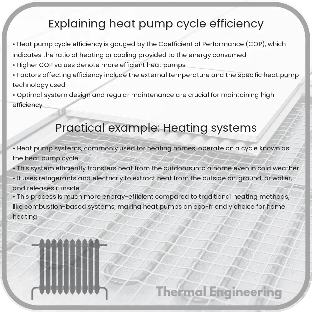
Heat pumps are commonly used devices in heating, ventilation, and air conditioning (HVAC) systems that transfer heat from one place to another by using a refrigerant under varying conditions of pressure and temperature. These devices operate on what is known as a heat pump cycle. Understanding the efficiency of this cycle not only helps in choosing the right heat pump but also improves overall energy management in residential and commercial settings.

Basics of the Heat Pump Cycle

The operation of a heat pump cycle revolves around four key components: the evaporator, the compressor, the condenser, and the expansion valve. The cycle involves the following steps:

  1. Evaporation: The refrigerant absorbs heat at low pressure in the evaporator, causing it to evaporate into a low-temperature vapor.
  2. Compression: The vapor is then compressed by the compressor, which increases its pressure and temperature.
  3. Condensation: The high-pressure, high-temperature vapor then flows through the condenser where it releases the absorbed heat and condenses into a liquid.
  4. Expansion: Finally, the high-pressure liquid passes through the expansion valve where its pressure is reduced, cooling it down before it returns to the evaporator to repeat the cycle.

Efficiency in a heat pump cycle is generally gauged by measuring the coefficient of performance (COP), which is the ratio of the heat output to the electrical energy input.

Understanding Coefficient of Performance (COP)

The coefficient of performance (COP) of a heat pump is a crucial measure of its efficiency. It is defined as:

COP = Qout / Win

where Qout is the amount of heat delivered by the heat pump (in joules or watts) and Win is the work input to the compressor (also in joules or watts).

Higher COP values indicate a more efficient heat pump as more heat is transferred per unit of work input. Typical COP values range from 3 to 5, meaning a heat pump can transfer 3 to 5 times more heat energy than the electrical energy it consumes.

Factors Affecting the Efficiency of Heat Pump Cycles

Several factors can influence the efficiency of a heat pump cycle:

  • Temperature Difference: The efficiency tends to decrease as the temperature difference between the heat source (such as the air or ground outside) and the heat sink (inside environment) increases. This is due to larger energy required to maintain the heat flow against a greater thermal gradient.
  • Quality of the Installation: Improper installation can lead to increased energy consumption and lower the COP. This includes issues like inadequate sizing, poor insulation, or incorrect placement of components.
  • Maintenance: Regular maintenance is crucial for optimal performance. Clogged filters, leaky ductwork, or low refrigerant levels can all diminish efficiency.
  • Type of Refrigerant: The type of refrigerant used can affect the efficiency as different refrigerants have different thermodynamic properties that impact the heat absorption and release processes.

Through understanding and optimizing these factors, the efficiency of heat pump systems can be significantly improved. This not only leads to reduced energy bills but also contributes to environmental sustainability by minimizing the usage of electrical energy and the associated emissions.

Conclusion

Heat pumps are a vital technology in modern HVAC systems. Understanding the efficiency of heat pump cycles and the factors that influence it is crucial for engineers, architects, and end-users aiming to enhance energy efficiency and system performance. With continued advances in technology and proper system management, heat pumps will remain integral to energy management strategies in both residential and commercial buildings.

Exploring and improving heat pump cycle efficiency not only saves costs but also aligns with global energy conservation and sustainability goals.

Understanding Fluid Couplings in Machines

Learn how fluid couplings transfer rotational power in machinery using hydraulic fluid, providing smooth torque and variable speed control.

Understanding Fluid Couplings in Machines

Understanding Fluid Couplings in Machines

Fluid couplings, often found in a variety of automotive and industrial applications, play a critical role in transferring rotational power from one shaft to another without direct mechanical contact. These devices use hydraulic fluid to transmit power and can also help in smoothing out torque delivery and providing variable speed and torque control. This article provides a simple overview of how fluid couplings work and where they are typically used.

What is a Fluid Coupling?

A fluid coupling consists of three main components: an impeller, a turbine, and a casing that holds the hydraulic fluid. The impeller is connected to the input shaft and acts as a pump, while the turbine is connected to the output shaft and acts like a turbine. Both the impeller and turbine are placed inside the casing, but they do not touch; the hydraulic fluid transmits the motion from one to the other.

How Do Fluid Couplings Work?

The primary mechanism of a fluid coupling is based on the transfer of rotational energy through the fluid movement between the impeller and the turbine. When the engine or motor rotates the impeller, it flings hydraulic fluid outward by centrifugal force. This movement of fluid impacts the turbine blades which are designed to capture this energy, turning the turbine and thus the output shaft.

Since there is no direct connection between the impeller and the turbine, the system allows for some degree of slippage. As the input speed increases, the fluid coupling gradually reduces slippage and increases efficiency in power transmission.

Advantages of Fluid Couplings

  • Smooth Start: Fluid couplings allow for a gradual increase of load, which provides a smooth and jerk-free start.
  • Overload Protection: By allowing slippage, the coupling can protect the drive system from damage due to sudden overloads.
  • Vibration Damping: Fluid couplings can reduce vibrations and shocks in the drive system, thus protecting the machinery and extending its life.
  • Load Balancing: In systems with multiple drive elements, fluid couplings ensure that the load is distributed evenly across each element.

Applications of Fluid Couplings

Fluid couplings are used in a variety of applications where variable speed operation and controlled start-up are necessary. Some common applications include:

  • Conveyors
  • Crushers
  • Marine Propulsion
  • Fans and Blowers
  • Railway Engines

Conclusion

Fluid couplings are essential components in modern machinery, providing flexibility and safety to complex mechanical systems. By transferring power through a fluid medium, they offer protections and operational advantages that solid couplings cannot. Whether it’s in heavy industry or in the transmission of a vehicle, understanding the basic function and benefits of fluid couplings can help in optimizing system performance and longevity.

The understanding of fluid mechanics, combined with mechanical engineering, forms the basis of designing and using fluid couplings efficiently. As technology advances, the role of fluid couplings remains pivotal in applications requiring smooth and effective transmission of power.

Principles of Hydrodynamic Lubrication

Hydrodynamic lubrication minimizes friction in machines by maintaining a fluid film between moving surfaces, crucial for mechanical efficiency and longevity.

Principles of Hydrodynamic Lubrication

Understanding the Principles of Hydrodynamic Lubrication

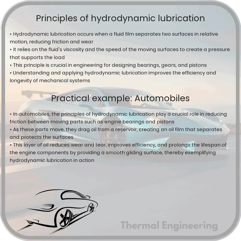
Hydrodynamic lubrication is a critical principle in the field of mechanical engineering, particularly concerning the efficient and safe operation of various machines with moving parts. It refers to a lubrication mechanism in which a fluid film separates two surfaces in relative motion, such as the surfaces of a bearing and a shaft, thus minimizing direct contact and reducing friction and wear.

Basic Concepts

At the heart of hydrodynamic lubrication is the generation of a pressure field within the lubricating fluid due to the motion of the contacting surfaces. This pressure field supports the load applied to the moving parts and keeps them separated by a thin layer of lubricant. The key parameters that influence hydrodynamic lubrication include:

  • Viscosity of the lubricant
  • Speed of the moving surfaces
  • Load on the surfaces
  • Geometry and roughness of the surfaces

How Hydrodynamic Lubrication Works

When two surfaces in a machine, such as a bearing and a shaft, begin to move relative to each other and a lubricant is present, the relative motion drags the lubricant into the converging gap between the surfaces. As the gap narrows, the lubricant’s velocity increases, and a pressure is built up within the fluid. This generated pressure is sufficient to lift the bearing surface, creating a separating film of lubricant between the bearing and the shaft.

This lubricating film is purely maintained by the motion-induced pressure and is thick enough to prevent metal-to-metal contact. Thus, wear is significantly reduced, and the efficiency of the machine is increased.

The Reynolds Equation

The behavior of the lubricant film in hydrodynamic lubrication can be described mathematically by the Reynolds Equation. This fundamental equation of fluid dynamics helps predict the pressure distribution in the lubricant film based on factors like lubricant viscosity, speed, and geometry of the surfaces:

\[ \frac{\partial}{\partial x}\left(h^3 \frac{\partial p}{\partial x}\right) + \frac{\partial}{\partial y}\left(h^3 \frac{\partial p}{\partial y}\right) = 6 \times \left(\frac{\partial h}{\partial t} + u \frac{\partial h}{\partial x} + v \frac{\partial h}{\partial y}\right) \]

Where:

  • p is the pressure in the fluid film
  • h is the film thickness
  • u, v are the velocities in the x and y directions, respectively
  • t represents time

Applications of Hydrodynamic Lubrication

Hydrodynamic lubrication is employed in various applications where durable and reliable lubrication is required, such as:

  • Automotive engines and gearboxes
  • Industrial machinery
  • Marine engines
  • Aerospace components
  • Turbines and generators

Efficient hydrodynamic lubrication not only prolongs the life of mechanical components but also enhances their operational efficiency and reliability. By understanding the principles behind hydrodynamic lubrication, engineers can design machines that perform effectively under varying conditions and loads.

Conclusion

The principles of hydrodynamic lubrication are fundamental to maintain the longevity and efficiency of mechanical systems with moving parts. Through the application of scientific principles and mathematical expressions like the Reynolds Equation, engineers can optimize and ensure the proper function of machinery in diverse industries.

As research continues, advancements in materials and lubricant formulations further refine the effectiveness of hydrodynamic lubrication, promising even greater performance and durability of mechanical systems in the future.

How Does Blood Flow Through Arteries?

Explore the dynamics of blood flow in arteries, focusing on fluid dynamics, artery structure, and impacts on cardiovascular health.

How Does Blood Flow Through Arteries?

Understanding How Blood Flows Through Arteries

The human circulatory system is a complex and vital system responsible for transporting blood, nutrients, oxygen, carbon dioxide, and hormones throughout the body. Central to this system are the arteries, which play a crucial role in directing blood flow from the heart to various parts of the body. This article explores the dynamics of how blood flows through arteries and the physical principles governing this essential physiological process.

Arterial Structure and Function

Arteries are blood vessels that carry oxygen-rich blood away from the heart. They are constructed of multiple layers: an inner lining called the endothelium, a middle layer of smooth muscle, and an outer layer of connective tissue. The elasticity of the artery walls is crucial for maintaining blood flow during the different phases of the cardiac cycle.

The Physics of Blood Flow

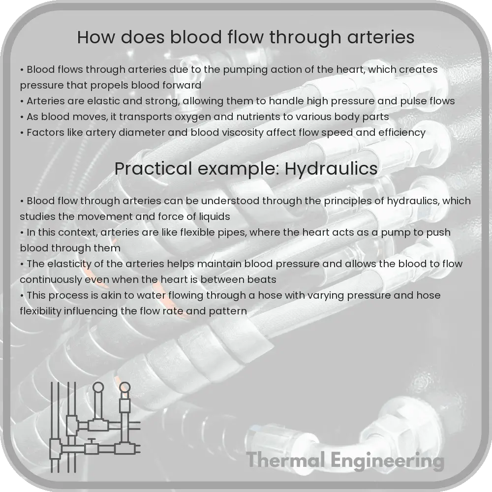
Blood flow through arteries can be primarily understood through principles of fluid dynamics. The flow of blood is influenced by several factors such as pressure, resistance, and the physical properties of blood and arterial walls.

  • Pressure Gradient: Blood flow is driven by a pressure gradient created by the heart’s pumping action. When the heart contracts, it generates high pressure (systolic pressure), forcing blood through the arterial system. Blood flow continues as the pressure decreases until the next heart contraction.
  • Poiseuille’s Law: This principle helps quantify blood flow (Q) through a cylindrical vessel based on the radius, length of the vessel, viscosity of the fluid, and pressure difference across the vessel. Mathematically, it is given by the equation:

    Q = (π * ΔP * r4) / (8 * μ * L),

    where ΔP is the pressure difference, r is the radius of the artery, μ is the viscosity of the blood, and L is the length of the artery.

  • Reynolds Number: The flow of blood can be laminar or turbulent, depending on the Reynolds number, which is calculated based on factors like blood velocity, arterial diameter, and blood viscosity. Laminar flow (smooth and regular) is typical in smaller arteries, while turbulent flow may occur in larger arteries or those with obstructions.

Role of Arterial Elasticity

Arterial elasticity plays a significant role in damping the pulsatile nature of blood flow, which is a result of the heart’s rhythmic contractions. This characteristic is due to the elastin and collagen fibers in the artery walls, allowing them to expand and contract, thereby smoothing out the pressure fluctuations and ensuring a more steady flow of blood through the arterial network.

Medical Implications

Understanding blood flow in arteries is critical for diagnosing and treating various cardiovascular diseases. Conditions like atherosclerosis (narrowing of arteries due to plaque buildup) can alter the dynamics of blood flow, leading to increased blood pressure and risk of heart attack or stroke. Medical interventions such as stents or bypass surgery are designed to restore normal blood flow and reduce these risks.

Conclusion

The study of how blood flows through arteries integrates principles of physics and biology to provide insights into human health and disease. By understanding the dynamics at play, medical professionals can better diagnose, treat, and manage cardiovascular conditions, ultimately leading to improved health outcomes.

What Is the Magnus Effect in Ball Sports?

Learn how the Magnus effect influences ball trajectories in sports by altering airflow and pressure around a spinning ball.

What Is the Magnus Effect in Ball Sports?

Understanding the Magnus Effect in Ball Sports

The Magnus effect is a physical phenomenon that has a significant impact on ball sports, influencing the trajectory and motion of spinning balls. Named after German physicist Heinrich Gustav Magnus, who described it in 1852, the Magnus effect helps explain the unexpected curves that balls exhibit in sports such as soccer, tennis, and baseball.

Physics Behind the Magnus Effect

When a ball is thrown or kicked with a spin, the rotation of the ball affects the air flow around it. Air flows faster on one side of the spinning ball and slower on the opposite side due to the spin. According to Bernoulli’s principle, faster airflow decreases the air pressure. Thus, on the side of the ball where the air moves quickly, the pressure is reduced. As a result, a pressure gradient is created towards the side of the ball with higher pressure, pushing the ball in that direction. This deflection in the flight path of the ball is what’s observed as the Magnus effect.

To visualize this, consider a soccer player curving the ball during a free kick. If the ball spins counter-clockwise from the player’s perspective, the left side of the ball would push the air faster, creating low pressure, and the ball curves to the left.

Mathematical Representation

The force exerted by the Magnus effect can be mathematically represented by:

F M = k * v * ω

  • FM is the Magnus force.
  • k represents a constant that includes factors like air density and the cross-sectional area of the ball.
  • v is the velocity of the ball.
  • ω (omega) is the angular velocity of the ball’s spin.

Applications in Sports

  • Soccer: Players utilize the Magnus effect to bend the ball around a wall of defenders and into the goal.
  • Tennis: Topspin and backspin are techniques that leverage the Magnus effect to control the ball’s bounce and trajectory.
  • Baseball: Pitchers throw curveballs that use the Magnus effect to drop or deviate the ball unexpectedly, deceiving the batter.
  • Golf: Golfers apply spins to control the ball’s flight path and landing behavior.

Practical Learning and Training

To master the use of the Magnus effect in sports, athletes typically go through extensive practice to fine-tune their technique. Understanding and predicting the effect requires practical experience, often supported by high-speed video analysis to observe the exact path of the ball and its spin.

In conclusion, the Magnus effect is a fascinating and complex phenomenon that adds depth to the gameplay in various ball sports, allowing players to exhibit greater skill and strategy. By mastering the Magnus effect, athletes can manipulate the ball in ways that might seem counterintuitive, showcasing the beautiful interplay between physics and sports.

Basics of Wind Tunnel Testing Explained

Learn about wind tunnel testing, its types, key components, processes, and applications across multiple industries to enhance design and safety.

Basics of Wind Tunnel Testing Explained

Introduction to Wind Tunnel Testing

Wind tunnel testing is a crucial process in aerodynamics, a branch of physics and engineering that studies the motion of air and other gaseous fluids, and the forces acting on bodies in motion through the air. Wind tunnels are used to simulate conditions that objects, such as aircraft, automobiles, and buildings, encounter in the real world. This testing enables engineers to study aerodynamic forces and make adjustments to improve the performance and safety of various structures and vehicles.

Types of Wind Tunnels

There are several types of wind tunnels, each designed for specific testing needs:

  • Subsonic Wind Tunnels: Used for testing scenarios where the airflow over the object is below the speed of sound (Mach 1).
  • Transonic Wind Tunnels: Useful for testing near the speed of sound (around Mach 0.8 to Mach 1.2), where both subsonic and supersonic flow can exist over different parts of the object being tested.
  • Supersonic and Hypersonic Wind Tunnels: These tunnels are designed to test objects at speeds greater than the speed of sound (Mach 1 and above).

Key Components of Wind Tunnels

A wind tunnel typically consists of a few key components:

  1. Settling Chamber: Filters the airflow to ensure smooth, consistent air conditions throughout the test section.
  2. Contraction Cone: Narrows the airflow to increase its speed while entering the test section.
  3. Test Section: The area where the model or prototype is placed and exposed to controlled airflow.
  4. Diffuser: Helps in reducing the speed and pressure of the air exiting the test section.
  5. Drive Section: Includes fans or compressors to propel the air through the tunnel.

How Wind Tunnel Testing is Conducted

The process of wind tunnel testing generally involves the following steps:

  • Preparation: The model or prototype is designed and constructed, often scaled down, and equipped with various sensors to measure forces, pressures, and other relevant parameters.
  • Calibration: The wind tunnel and all measurement instruments are calibrated to ensure accurate data collection.
  • Testing: The model is positioned in the test section, and air is flowed over it. Conditions such as wind speed, angle of attack, and side slip are carefully controlled and varied systematically.
  • Data Collection: Sensors and cameras capture data, which is then analyzed by engineers to understand the aerodynamic properties and behaviors under different conditions.
  • Modification and Re-testing: Based on initial findings, adjustments may be made to the design, and further tests are usually conducted to optimize performance and safety.

Applications of Wind Tunnel Testing

Wind tunnel testing is vital in many fields:

  • Aerospace Engineering: For the design and testing of aircraft and spacecraft to ensure aerodynamic efficiency and safety.
  • Automotive Industry: To refine the shape and structure of vehicles for better fuel efficiency and handling stability.
  • Construction and Civil Engineering: To analyze how wind impacts buildings, bridges, and other structures and to design them to withstand wind loads.
  • Sports: Used to improve performance and comfort in sports equipment and apparel, including cycling helmets and racing uniforms.

Conclusion

Wind tunnel testing is an indispensable part of design and engineering, providing essential insights into fluid dynamics that impact the real-world performance of various systems and structures. By understanding and harnessing wind tunnel testing, engineers can create more efficient, stable, and safe designs that meet the demanding conditions they will face once deployed.

How Do Fluid Filters Cleanse and Purify?

Learn about the principles, types, and applications of fluid filtration used in diverse industries for purifying liquids and gases.

How Do Fluid Filters Cleanse and Purify?

How Do Fluid Filters Cleanse and Purify?

Fluid filtration is a crucial process used in a variety of applications, from water purification systems to oil refineries, providing a reliable method for removing impurities and contaminants from liquids. This article explores the fundamental principles behind fluid filters, how they operate, and their importance in everyday and industrial contexts.

Basic Principles of Fluid Filtration

Filtration is the process of separating solids from liquids or gases by passing them through a medium that allows only certain components to pass through. The medium used for filtration is known as a filter, which can vary widely in material, pore size, and design, depending on the specific requirements of the application.

  • Mechanical Filtration: This involves physically trapping solids or particulate matter. Filters used in mechanical filtration typically include materials like polypropylene, nylon, or metal meshes with defined pore sizes that prevent particles larger than the mesh size from passing through.
  • Biological Filtration: Utilized primarily in water treatment, this method involves using natural processes where bacteria or other microorganisms break down organic impurities. The filter medium provides a surface for these organisms to grow and perform biological cleansing.
  • Chemical Filtration: This process uses a medium that removes impurities through a chemical reaction, such as adsorption. Activated carbon is a common filter material that captures various chemicals and odors through its vast surface area.

Types of Fluid Filters

There are numerous types of filters, each designed to address specific kinds of impurities and fluid characteristics:

  1. Screen Filters: These are simple, effective solutions for removing large particles. They have screens with holes of a specific size, suited for applications where large particulate filtration is sufficient.
  2. Cartridge Filters: Used for finer filtration, cartridge filters can remove smaller particles. These are typically disposable and are used in residential water purifiers, HVAC systems, and more.
  3. Sand Filters: Commonly used in large-scale water treatment, such as swimming pools and municipal water systems. Water is passed through a bed of sand that traps particulate matter.
  4. HEPA Filters: High Efficiency Particulate Air (HEPA) filters can trap very fine particles effectively. These are extensively used in environments that require very clean air, such as hospitals and laboratories.

Applications of Fluid Filtration

Filtration is employed in a wide array of applications across many industries:

  • Drinking Water Purification: To ensure safety and quality, water is filtered to remove microorganisms and impurities that can pose health risks.
  • Wastewater Treatment: Filtration processes are essential in treating industrial and municipal wastewater before it is discharged into natural bodies or reused.
  • Pharmaceuticals: Stringent purity standards in this industry require advanced filtration methods to ensure that products are free from contaminants.
  • Food and Beverage Industry: Filtration is used to clarify liquids and ensure that products meet regulatory and consumer standards for purity and taste.

Importance of Filtration

Filtration plays a vital role in protecting human health, preserving environmental quality, and ensuring the purity of products in industrial processes. By removing unwanted substances from fluids, filters contribute significantly to the safety, efficiency, and sustainability of many systems. As technology advances, the development of more efficient and selective filters continues to expand the possibilities and effectiveness of filtration across various fields.

Understanding the basics of fluid filtration not only highlights its importance but also its vast application in everyday life and in complex industrial processes. Whether it’s the water we drink or the air we breathe, filtration systems help maintain essential cleanliness and safety standards that enhance the quality of life and protect the environment.