Example of Heat Equation – Problem with Solution
Heat Conduction in a Large Plane Wall
Example of Heat Equation – Problem with Solution
Consider the plane wall of thickness 2L, in which there is uniform and constant heat generation per unit volume, qV [W/m3]. The centre plane is taken as the origin for x and the slab extends to + L on the right and – L on the left. For constant thermal conductivity k, the appropriate form of the heat equation, is:
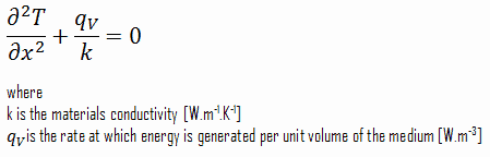
The general solution of this equation is:
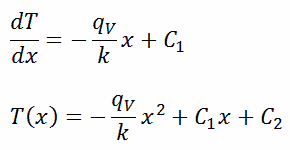
where C1 and C2 are the constants of integration.
1)
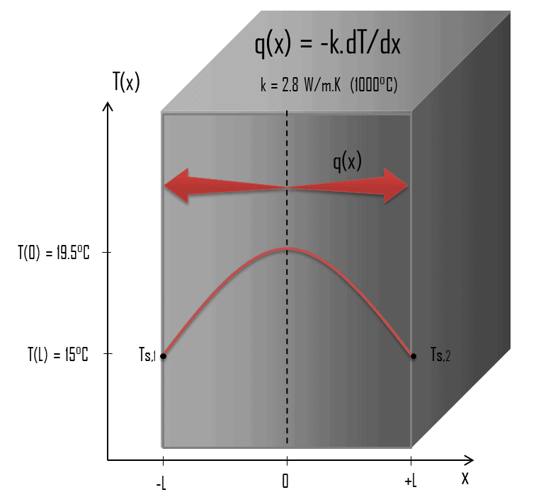 Calculate the temperature distribution, T(x), through this thick plane wall, if:
- the temperatures at both surfaces are 15.0°C
- the thickness this wall is 2L = 10 mm.
- the materials conductivity is k = 2.8 W/m.K (corresponds to uranium dioxide at 1000°C)
- the volumetric heat rate is qV = 106 W/m3
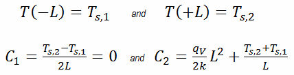
In this case, the surfaces are maintained at given temperatures Ts,1 and Ts,2. This corresponds to the Dirichlet boundary condition. Moreover, this problem is thermally symmetric and therefore we may use also thermal symmetry boundary condition. The constants may be evaluated using substitution into the general solution and are of the form:
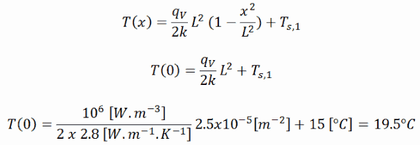
The resulting temperature distribution and the centerline (x = 0) temperature (maximum) in this plane wall at these specific boundary conditions will be:
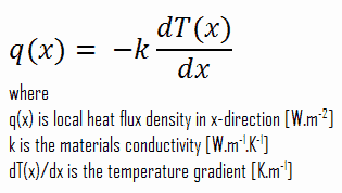
The heat flux at any point, qx [W.m-2], in the wall may, of course, be determined by using the temperature distribution and with the Fourier’s law. Note that, with heat generation the heat flux is no longer independent of x, the therefore:
Example of Heat Equation – Problem with Solution
Heat Conduction in a Fuel Rod
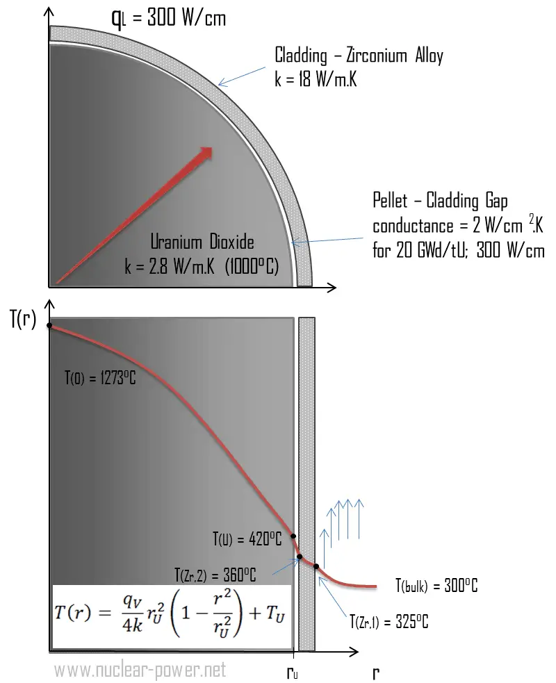
Most of PWRs use the uranium fuel, which is in the form of uranium dioxide. Uranium dioxide is a black semiconducting solid with very low thermal conductivity. On the other hand the uranium dioxide has very high melting point and has well known behavior. The UO2 is pressed into cylindrical pellets, these pellets are then sintered into the solid.
These cylindrical pellets are then loaded and encapsulated within a fuel rod (or fuel pin), which is made of zirconium alloys due to its very low absorption cross-section (unlike the stainless steel). The surface of the tube, which covers the pellets, is called fuel cladding.
See also: Thermal Conduction of Uranium Dioxide
Thermal and mechanical behavior of fuel pellets and fuel rods constitute one of three key core design disciplines. Nuclear fuel is operated under very inhospitable conditions (thermal, radiation, mechanical) and must withstand more than normal conditions operation. For example temperatures in the centre of fuel pellets reach more than 1000°C (1832°F) accompanied by fission-gas releases. Therefore detailed knowledge of temperature distribution within a single fuel rod is essential for safe operation of nuclear fuel. In this section we will study heat conduction equation in cylindrical coordinates using Dirichlet boundary condition with given surface temperature (i.e. using Dirichlet boundary condition). Comprehensive analysis of fuel rod temperature profile will be studied in separate section.
Temperature in the centerline of a fuel pellet
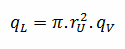
Consider the fuel pellet of radius rU = 0.40 cm, in which there is uniform and constant heat generation per unit volume, qV [W/m3]. Instead of volumetric heat rate qV [W/m3], engineers often use the linear heat rate, qL [W/m], which represents the heat rate of one meter of fuel rod. The linear heat rate can be calculated from the volumetric heat rate by:
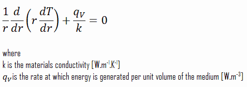
The centreline is taken as the origin for r-coordinate. Due to symmetry in z-direction and in azimuthal direction, we can separate of variables and simplify this problem to one-dimensional problem. Thus, we will solve for the temperature as function of radius, T(r), only. For constant thermal conductivity, k, the appropriate form of the cylindrical heat equation, is:
The general solution of this equation is:
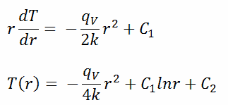
where C1 and C2 are the constants of integration.
 Calculate the temperature distribution, T(r), in this fuel pellet, if:
- the temperatures at the surface of the fuel pellet is TU = 420°C
- the fuel pellet radius rU = 4 mm.
- the averaged material’s conductivity is k = 2.8 W/m.K (corresponds to uranium dioxide at 1000°C)
- the linear heat rate is qL = 300 W/cm and thus the volumetric heat rate is qV = 597 x 106 W/m3
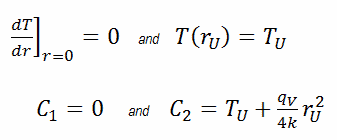
In this case, the surface is maintained at given temperatures TU. This corresponds to the Dirichlet boundary condition. Moreover, this problem is thermally symmetric and therefore we may use also thermal symmetry boundary condition. The constants may be evaluated using substitution into the general solution and are of the form:
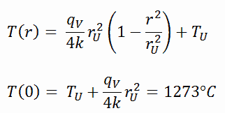
The resulting temperature distribution and the centerline (r = 0) temperature (maximum) in this cylindrical fuel pellet at these specific boundary conditions will be:
The radial heat flux at any radius, qr [W.m-1], in the cylinder may, of course, be determined by using the temperature distribution and with the Fourier’s law. Note that, with heat generation the heat flux is no longer independent of r.
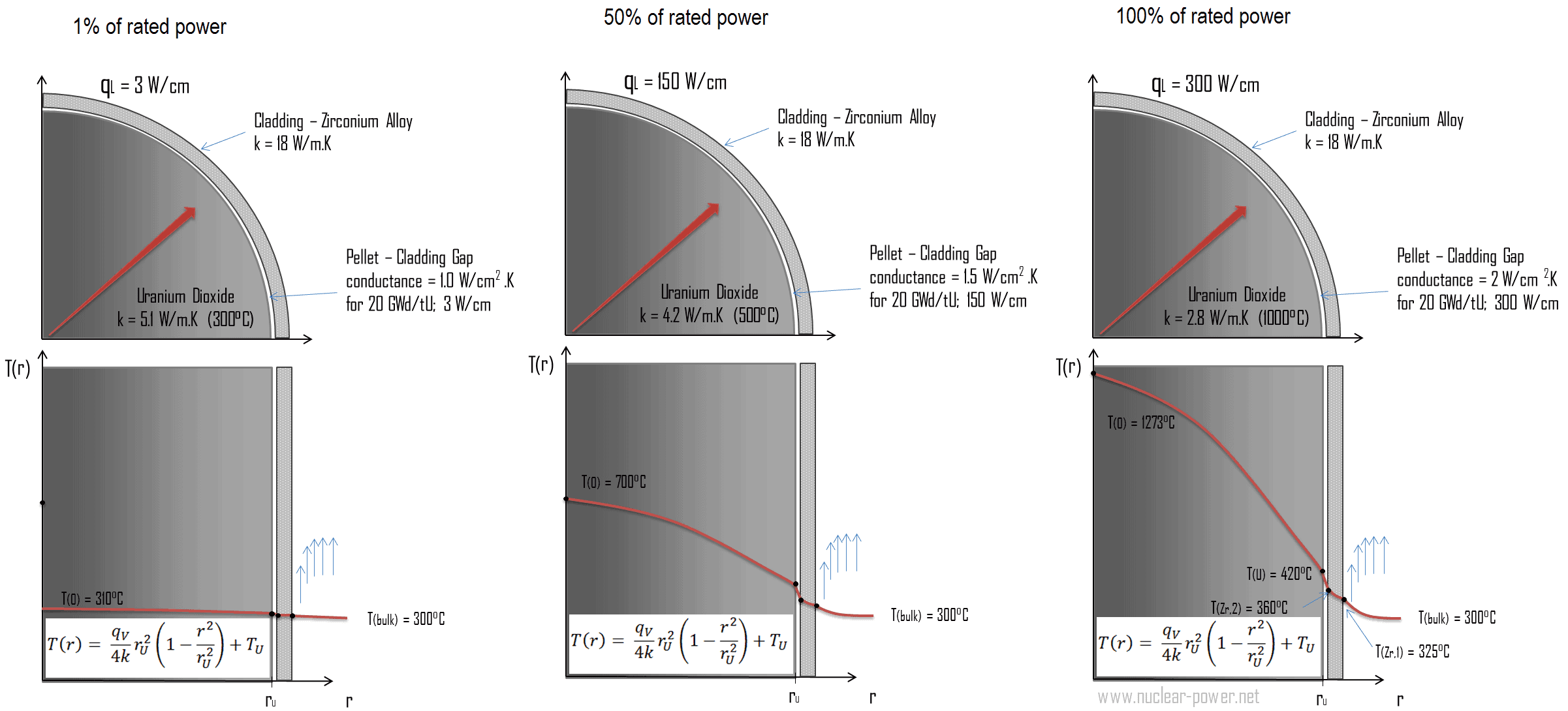
The following figure shows the temperature distribution in the fuel pellet at various power levels.
______
The temperature in an operating reactor varies from point to point within the system. As a consequence, there is always one fuel rod and one local volume, that are hotter than all the rest. In order to limit these hot places the peak power limits must be introduced. The peak power limits are associated with a boiling crisis and with the conditions which could cause fuel pellet melt. However, metallurgical considerations place an upper limits on the temperature of the fuel cladding and the fuel pellet. Above these temperatures there is a danger that the fuel may be damaged. One of the major objectives in the design of a nuclear reactors is to provide for the removal of the heat produced at the desired power level, while assuring that the maximum fuel temperature and the maximum cladding temperature are always below these predetermined values.
Temperature distribution in Fuel Cladding
Cladding is the outer layer of the fuel rods, standing between the reactor coolant and the nuclear fuel (i.e. fuel pellets). It is made of a corrosion-resistant material with low absorption cross section for thermal neutrons, usually zirconium alloy. Cladding prevents radioactive fission products from escaping the fuel matrix into the reactor coolant and contaminating it. Cladding constitute one of barriers in ‘defence-in-depth‘ approach.
Consider the fuel cladding of inner radius rZr,2 = 0.408 cm and outer radius rZr,1 = 0.465 cm. In comparison to fuel pellet, there is almost no heat generation in the fuel cladding (cladding is slightly heated by radiation). All heat generated in the fuel must be transferred via conduction through the cladding and therefore the inner surface is hotter than the outer surface.
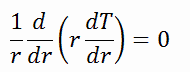
To find the temperature distribution through the cladding we must solve the heat conduction equation. Due to symmetry in z-direction and in azimuthal direction, we can separate of variables and simplify this problem to one-dimensional problem. Thus, we will solve for the temperature as function of radius, T(r), only. In this example, we will assume that there is strictly no heat generation within the cladding. For constant thermal conductivity, k, the appropriate form of the cylindrical heat equation, is:
The general solution of this equation is:
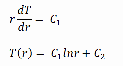
where C1 and C2 are the constants of integration.
1)
Calculate the temperature distribution, T(r), in this fuel cladding, if:
- the temperature at the inner surface of the cladding is TZr,2 = 360°C
- the temperature of reactor coolant at this axial coordinate is Tbulk = 300°C
- the heat transfer coefficient (convection; turbulent flow) is h = 41 kW/m2.K.
- the averaged material’s conductivity is k = 18 W/m.K
- the linear heat rate of the fuel is qL = 300 W/cm and thus the volumetric heat rate is qV = 597 x 106 W/m3
From the basic relationship for heat transfer by convection we can calculate the outer surface of the cladding as:
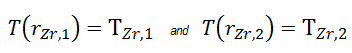
As can be seen, also in this case we have given surface temperatures TZr,1 and TZr,2. This corresponds to the Dirichlet boundary condition. The constants may be evaluated using substitution into the general solution and are of the form:
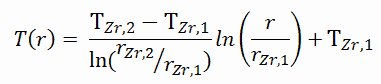
Solving for C1 and C2 and substituting into the general solution, we then obtain:
∆T – cladding surface – coolant
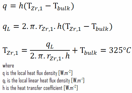
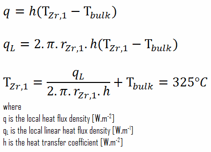
Detailed knowledge of geometry, outer radius of cladding, linear heat rate, convective heat transfer coefficient and the coolant temperature determines ∆T between the coolant (Tbulk) and the cladding surface (TZr,1). Therefore we can calculate the cladding surface temperature (TZr,1) simply using the Newton’s Law:
∆T in fuel cladding
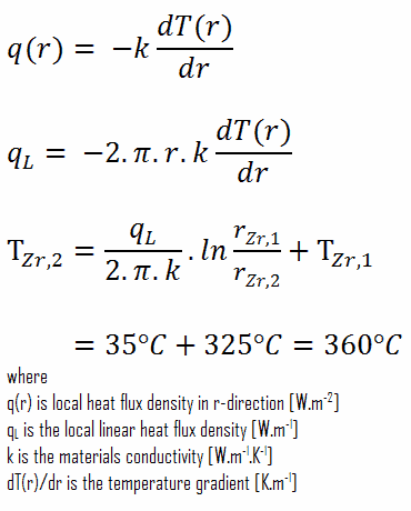
Detailed knowledge of geometry, outer and inner radius of cladding, linear heat rate, and the cladding surface temperature (TZr,1) determines ∆T between outer and inner surfaces of cladding. Therefore we can calculate the inner cladding surface temperature (TZr,2) simply using the Fourier’s Law:
We hope, this article, Example of Heat Equation – Problem with Solution, helps you. If so, give us a like in the sidebar. Main purpose of this website is to help the public to learn some interesting and important information about thermal engineering.