Facebook Instagram Youtube Twitter

What is Boiling Crisis – Critical Heat Flux – Definition

Boiling Crisis – Critical Heat Flux. Dynamic changes of boiling regime associated with exceeding the critical heat flux are widely known as “boiling crisis”. Thermal Engineering

Boiling Crisis

In this chapter, we will study flow boiling in a vertical heated channel. The regimes of boiling and the heat flux curve are similar (not the same) to the ones in pool boiling. The process occurs also in modern high pressure forced circulation boilers.
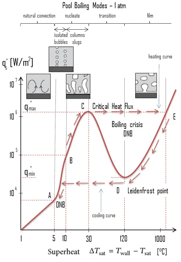
Boiling Curve - Boiling ModesThe pioneering work on pool boiling was done in 1934 by S. Nukiyama, who used electrically heated nichrome and platinum wires immersed in liquids in his experiments. Nukiyama was the first to identify different regimes of pool boiling using his apparatus. He noticed that boiling takes different forms, depending on the value of the wall superheat temperature ΔTsat (known also as the excess temperature), which is defined as the difference between the wall temperature, Twall and the saturation temperature, Tsat.

Four different boiling regimes  of pool boiling (based on the excess temperature) are observed:

  • Natural Convection Boiling                            ΔTsat < 5°C
  • Nucleate Boiling                                   5°C < ΔTsat < 30°C
  • Transition Boiling                                 30°C < ΔTsat < 200°C
  • Film Boiling                                        200°C < ΔTsat

These regimes are illustrated on the boiling curve in the figure, which is a plot of heat flux versus the excess temperature. Although the boiling curve given in this figure is for water, the general shape of the boiling curve remains the same for different coolants. Note that, the specific shape of the curve depends also on the system parameters such as the pressure and coolant flow rate, but it is practically independent of the geometry of the heating surface. For flow boiling as in the fuel channel, the curve will be different, but major results will be similar.

In BWRs boiling of coolant occurs at normal operation and it is very desired phenomenon. Typical flow qualities in BWR cores are on the order of 10 to 20 %.

Although the earliest core designs assumed that surface boiling could not be allowed in PWRs, this assumption was soon rejected and two-phase heat transfer is now one of normal operation heat transfer mechanisms also in PWRs.

In both designs, the nucleate boiling heat flux cannot be increased indefinitely. At some value, we call it the “critical heat flux” (CHF), the steam produced can form an insulating layer over the surface, which in turn deteriorates the heat transfer coefficient. Dynamic changes of boiling regime associated with exceeding the critical heat flux are widely known as “boiling crisis”.

The boiling crisis can be classified as:

  • dryout (will be described below DNB) in the high-quality region
  • departure from nucleate boiling (DNB) in the subcooled or low-quality region (approximate quality range: from –5% to +5%).

But the critical heat flux is used for both regimes.

Note that, the opposite phenomenon to DNB is known as return to nucleate boiling (RNB) and occurs at point D, which is known as the Leidenfrost point.

Critical Heat Flux
Dryout vs. DNBAs was written, in nuclear reactors, limitations of the local heat flux is of the highest importance for reactor safety. For pressurized water reactors and also for boiling water reactors, there are thermal-hydraulic phenomena, which cause a sudden decrease in the efficiency of heat transfer (more precisely in the heat transfer coefficient). These phenomena occur at certain value of heat flux, known as the “critical heat flux”. The phenomena, that cause the deterioration of heat transfer are different for PWRs and for BWRs.

In both types of reactors, the problem is more or less associated with departure from nucleate boiling. The nucleate boiling heat flux cannot be increased indefinitely. At some value, we call it the “critical heat flux” (CHF), the steam produced can form an insulating layer over the surface, which in turn deteriorates the heat transfer coefficient. Immediately after the critical heat flux has been reached, boiling become unstable and film boiling occurs. The transition from nucleate boiling to film boiling is known as the “boiling crisis”. As was written, the phenomena, that cause the deterioration of heat transfer are different for PWRs and for BWRs.

Departure From Nucleate Boiling – DNB

DNBR - Departure from Nucleate Boiling RatioIn case of PWRs, the critical safety issue is named DNB (departure from nucleate boiling), which causes the formation of a local vapor layer, causing a dramatic reduction in heat transfer capability. This phenomenon occurs in the subcooled or low-quality region. The behaviour of the boiling crisis depends on many flow conditions (pressure, temperature, flow rate), but the boiling crisis occurs at a relatively high heat fluxes and appears to be associated with the cloud of bubbles, adjacent to the surface. These bubbles or film of vapor reduces the amount of incoming water. Since this phenomenon deteriorates the heat transfer coefficient and the heat flux remains, heat then accumulates in the fuel rod causing dramatic rise of cladding and fuel temperature. Simply, a very high temperature difference is required to transfer the critical heat flux being produced from the surface of the fuel rod to the reactor coolant (through vapor layer).

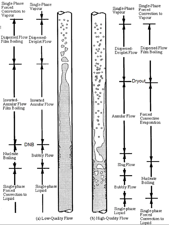
In case of PWRs, the critical flow is inverted annular flow, while in BWRs, the critical flow is usually annular flow. The difference in flow regime between post-dryout flow and post-DNB flow is depicted in the figure. In PWRs at normal operation the flow is considered to be single-phase. But a great deal of study has been performed on the nature of two-phase flow in case of transients and accidents (such as the loss-of-coolant accident – LOCA or trip of RCPs), which are of importance in reactor safety and in must be proved and declared in the Safety Analysis Report (SAR).

In pressurized water reactors, one of key safety requirements is that a departure from nucleate boiling (DNB) will not occur during steady state operation, normal operational transients, and anticipated operational occurrences (AOOs).  Fuel cladding integrity will be maintained if the minimum DNBR remains above the 95/95 DNBR limit for PWRs ( a 95% probability at a 95% confidence level). DNB criterion is one of acceptance criteria in safety analyses as well as it constitutes one of safety limits in technical specifications.

An important duty of the plant operator is to control plant parameters such that a safe margin to DNB (or distance from DNB on the heat transfer curve) is maintained. Any sudden, large change in the following plant parameters/directions will decrease the margin to DNB:

  • Decrease in reactor coolant pressure
  • Decrease in reactor coolant flow rate
  • Increase in reactor power
  • Increase in reactor coolant inlet temperature

Therefore, the function of the operators and the plant design is to prevent a sudden, large change in these plant parameters.

Heat Flux Limitations in Nuclear Reactors
Nuclear reactors produce enormous amount of heat (energy) in a small volume. The density of the energy generation is very large and this puts demands on its heat transfer system (reactor coolant system). For a reactor to operate in a steady state, all of the heat released in the system must be removed as fast as it is produced. This is accomplished by passing a liquid or gaseous coolant through the core and through other regions where heat is generated. The heat transfer must be equal to or greater than the heat generation rate or overheating and possible damage to the fuel may occur.

The temperature in an operating reactor varies from point to point within the system. As a consequence, there is always one fuel rod and one local volume, that are hotter than all the rest. In order to limit these hot places the peak power limits must be introduced. The peak power limits are associated with such phenomena as the departure from nucleate boiling and with the conditions which could cause fuel pellet melt.

Therefore power distribution within the core must be properly limited. These limitations are usually divided into two basic categories:

Critical Heat Flux for DNB – Correlations

As was written, the boiling crisis can be classified as dryout (will be described below DNB) in the high-quality region and departure from nucleate boiling (DNB) in the subcooled or low-quality region (approximate quality range: from –5% to +5%). But the critical heat flux is used for both regimes.

DNB – W-3 Correlation

One of the most well known design correlations for predicting departure from nucleate boiling is the W-3 correlation developed at the Westinghouse Atomic Power Division by Tong. It is applicable for subcooled and low to moderate quality flows.The W-3 correlation is a function of coolant enthalpy (saturated and inlet), pressure, quality and coolant mass flux:

CHF - Critical Heat Flux - Correlation

The correlation W-3 is for critical heat flux in uniformly heated channels. To account for non-uniform heat fluxes, Tong introduced the correction factor, F.

Special Reference: Tong, L. S., Weisman, Joel. Thermal Analysis of Pressurized Water Reactors. Amer Nuclear Society, 3rd edition, 5/1996. ISBN-13: 978-0894480386.

Cold Wall Factor – CWF

Tong, L. S. and Weisman, Joel also introduces a new factor known as the “cold wall factor”, which corrects CHF in a channel containing an unheated wall (e.g. channel adjacent to control rod guide tube). In these channels, liquid film builds up along the cold wall and this fluid is not effective in cooling the heated surface and the fluid cooling the heated surface is at higher enthalpy than calculated without assumption of cold wall. Note that, there is an assumption that cold wall deteriorates heat transfer compared to channel with all sides heated at the same bulk exit enthalpy.

CHF Look-up Tables

CHF look-up tables are used widely for the prediction of the critical heat flux (CHF). The CHF look-up table is basically a normalized data bank for a vertical 8 mm water-cooled tube. The 2006 CHF look-up table is based on a database containing more than 30,000 data points and they cover the ranges of 0.1–21 Mpa pressure, 0–8000 kg.m–2.s-1 (zero flow refers to pool-boiling conditions) mass flux and –0.5 to 1 vapour quality (negative qualities refer to subcooled conditions).

Special Reference: GROENEVELD, D.C. et al., The 2006 look-up table, Nuclear Engineering and Design 237 (2007), 1909–1922.

Departure from Nucleate Boiling Ratio – DNBR

As was written, in case of PWRs, the critical safety issue is named DNB (departure from nucleate boiling), which causes the formation of a local vapor layer, causing a dramatic reduction in heat transfer capability. Note that, even for BWRs, which have a significantly bottom-peaked axial power profile, the DNB-risk have to be taken into account.

DNB occurs, when the local heat flux reaches value of critical heat flux. This phenomenon occurs in the subcooled or low-quality region (approximate quality range: from –5% to +5%). The behaviour of this type of boiling crisis depends on many flow conditions (pressure, temperature, flow rate), since the critical heat flux is generally a function  of coolant enthalpy (saturated and inlet), pressure, quality and coolant mass flux:

CHF - Critical Heat Flux - Correlation

This type of boiling crisis occurs at a relatively high heat fluxes and appears to be associated with the cloud of bubbles, adjacent to the surface. These bubbles or film of vapor reduces the amount of incoming water. Since this phenomenon deteriorates the heat transfer coefficient and the heat flux remains, heat then accumulates in the fuel rod causing dramatic rise of cladding and fuel temperature. Simply, a very high temperature difference is required to transfer the critical heat flux being produced from the surface of the fuel rod to the reactor coolant (through vapor layer). In case of PWRs, the critical flow is inverted annular flow, while in BWRs, the critical flow is usually annular flow.

In pressurized water reactors, one of key safety requirements is that a departure from nucleate boiling (DNB) will not occur during steady state operation, normal operational transients, and anticipated operational occurrences (AOOs).  Fuel cladding integrity will be maintained if the minimum DNBR remains above the 95/95 DNBR limit for PWRs ( a 95% probability at a 95% confidence level). DNB criterion is one of acceptance criteria in safety analyses as well as it constitutes one of safety limits in technical specifications. Needless to say, the establishment of a minimum DNB ratio provides a major limitation on the design of water cooled reactors. This phenomenon limits the maximal thermal power of each PWR.

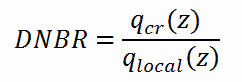
DNB ratio (DNBR – Departure from Nucleate Boiling Ratio) is the measure of the margin to critical heat flux. DNBR is defined as:

the critical heat flux at a specific location and specific coolant parameters divided by the operating local heat flux at that location.
DNBR - definition

The reactor core must be designed to keep the DNBR larger than the minimum allowable value (known as the correlation limit) during steady state operation, normal operational transients, and anticipated operational occurrences (AOOs). For predicting departure from nucleate boiling, CHF can be, for example, determined using the W-3 correlation developed at the Westinghouse Atomic Power Division. If these correlation were perfect (without uncertainties), the criterion would be simple:
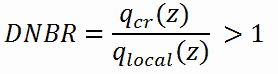
DNBR - criterion

Local heat flux must be lower than critical heat flux (i.e. DNBR must be higher than one).

DNBR - Departure from Nucleate Boiling RatioBut in reality, no correlation is perfect and uncertainties must be involved in this calculation. These uncertainty bands or error bounds establish a minimum acceptable value for the DNB Ratio, which may be significantly greater than one as indicated in the figure. Uncertainties may reach about 20% and therefore the DNBR must be larger than, for example, DNBRlim = 1,2.

As can be seen from the figure, the CHF significantly decreases with increasing coolant enthalpy, therefore minimal value of DNBR is not necessarily in the center of the core. The Minimum DNB Ratio (MDNBR) occurs at the location where the critical heat flux and the operating heat flux are the closest and it is usually in the upper part of the core. Moreover, at the channel inlet where the coolant subcooling is the highest, we would expect the heat flux necessary to cause DNB at this location to be extremely high. On the other hand, at the channel exit where the coolant enthalpy is its highest, the heat flux necessary to cause DNB should be at its lowest.

Special Reference: Tong, L. S., Weisman, Joel. Thermal Analysis of Pressurized Water Reactors. Amer Nuclear Society, 3rd edition, 5/1996. ISBN-13: 978-0894480386.
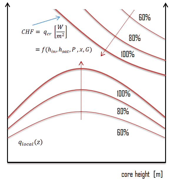
critical heat flux vs local heat flux

 
The Nuclear Enthalpy Rise Hot Channel Factor – FΔH
See also: Hot Channel Factors

The Nuclear Enthalpy Rise Hot Channel Factor – FNΔH is defined as:

  1. The ratio of the integral of linear power along the fuel rod on which minimum departure from nucleate boiling ratio occurs (during AOOs) , to the average fuel rod power in the core.
  2. The ratio of the integral of linear power along the fuel rod with the highest integrated power [kW/rod] to the average rod power [kW/rod].

Operation within the Nuclear Enthalpy Rise Hot Channel Factor – FNΔH limits prevents departure from nucleate boiling (DNB) during accidents, that are limiting from DNB point of view. For example, a loss of forced reactor coolant flow accident, a loss of normal feedwater flow or an inadvertent opening of a pressurizer relief valve. The Nuclear Enthalpy Rise Hot Channel Factor FNΔH is an assumption in these and other analyses as well as it is an assumption for Safety Limits (SLs) calculations. Its merit is that FNΔH provides with an information about power distribution as well as about the coolant temperature (enthalpy). Both are crucial for DNB occurrence. Operation beyond the Nuclear Enthalpy Rise Hot Channel Factor – FNΔH could invalidate core power distribution assumptions used in these analyses (Safety Analyses and Safety Limits derivation).

Post-DNB Heat Transfer

The nucleate boiling heat flux cannot be increased indefinitely. At some value, we call it the “critical heat flux” (CHF), the steam produced can form an insulating layer over the surface, which in turn deteriorates the heat transfer coefficient. This is because a large fraction of the surface is covered by a vapor film, which acts as an thermal insulation due to the low thermal conductivity of the vapor relative to that of the liquid. Immediately after the critical heat flux has been reached, boiling become unstable and transition boiling occurs. The transition from nucleate boiling to film boiling is known as the “boiling crisis”. Since beyond the CHF point the heat transfer coefficient decreases, the transition to film boiling is usually inevitable.

Boiling Curve - Boiling ModesA further increase in the heat flux is not necessary to maintain film boiling. A film of vapour fully covers the surface. This significantly reduces the convection coefficient, since the vapor layer has significantly lower heat transfer ability. As a result the excess temperature shoots up to a very high value. Beyond the Leidenfrost point, a continuous vapor film blankets the surface and there is no contact between the liquid phase and the surface. In this situation the heat transfer is both by radiation and by conduction to the vapour. Heated surface stabilizes stabilizes its temperature at point E (see figure). If the material is not strong enough for withstanding this temperature, the equipment will fail by damage to the material.

Critical Power Ratio – Dryout

Flow Boiling - DryoutIn BWRs, similar phenomenon is known as “dryout” and it is directly associated with changes in flow pattern during evaporation in the high-quality region. At given combinations of flow rate through a channel, pressure, flow quality, and linear heat rate, the wall liquid film may exhaust and the wall may be dried out. At normal, the fuel surface is effectively cooled by boiling coolant. However when the heat flux exceeds a critical value (CHF – critical heat flux) the flow pattern may reach the dryout conditions (thin film of liquid disappears). The heat transfer from the fuel surface into the coolant is deteriorated, with the result of a drastically increased fuel surface temperature. In the high-quality region, the crisis occurs at a lower heat flux. Since the flow velocity in the vapor core is high, post-CHF heat transfer is much better than for low-quality critical flux (i.e. for PWRs temperature rises are higher and more rapid).

Typical flow boiling modes in a vertical channel are depicted in the figure. This figure shows the typical order of the flow regimes that are encountered from inlet to outlet of a heated channel. At the inlet, the liquid enters subcooled (at the lower temperature than saturation). In this region the flow is single-phase. As the liquid heats up, the wall temperature correspondingly rises. As the wall temperature exceeds the saturation temperature (e.g. 285°C at 6.8 MPa), subcooled nucleate boiling begins. Bubbles nucleate in the superheated thermal boundary layer on the heated wall but tend to condense in the subcooled bulk.

Further increase in liquid temperature causes, that the liquid bulk reaches its saturation temperature and the convective boiling process passes through the bubbly flow into the slug flow. Increasing void fraction causes that the structure of the flow becomes unstable. The boiling process passes through the slug and churn flow into the annular flow regime with its characteristic annular film of the liquid. At given combinations of flow rate through a channel, pressure, flow quality, and linear heat rate, the wall liquid film may exhaust and the wall may be dried out. At the dryout point the wall temperature significantly rises in order to dissipate the applied heat flux. The post-dryout flow (mist or drop flow) in the heated channel is undesirable, because the presence of such flow regime is accompanied with significantly higher wall temperatures and high fluctuation of wall temperatures.

In this case, engineers define parameter known as the minimum critical power ratio (MCPR) instead of DNBR. The critical power ratio (CPR) is used for determining the thermal limits of boiling water reactors.

Definition of CPR :

The CPR is that power in the assembly that is calculated by application of the appropriate correlation(s) to cause some point in the assembly to experience boiling transition, divided by the actual assembly operating power.

Special Reference: Tong, L. S., Weisman, Joel. Thermal Analysis of Pressurized Water Reactors. Amer Nuclear Society, 3rd edition, 5/1996. ISBN-13: 978-0894480386.

 
References:
Heat Transfer:
  1. Fundamentals of Heat and Mass Transfer, 7th Edition. Theodore L. Bergman, Adrienne S. Lavine, Frank P. Incropera. John Wiley & Sons, Incorporated, 2011. ISBN: 9781118137253.
  2. Heat and Mass Transfer. Yunus A. Cengel. McGraw-Hill Education, 2011. ISBN: 9780071077866.
  3. U.S. Department of Energy, Thermodynamics, Heat Transfer and Fluid Flow. DOE Fundamentals Handbook, Volume 2 of 3. May 2016.

Nuclear and Reactor Physics:

  1. J. R. Lamarsh, Introduction to Nuclear Reactor Theory, 2nd ed., Addison-Wesley, Reading, MA (1983).
  2. J. R. Lamarsh, A. J. Baratta, Introduction to Nuclear Engineering, 3d ed., Prentice-Hall, 2001, ISBN: 0-201-82498-1.
  3. W. M. Stacey, Nuclear Reactor Physics, John Wiley & Sons, 2001, ISBN: 0- 471-39127-1.
  4. Glasstone, Sesonske. Nuclear Reactor Engineering: Reactor Systems Engineering, Springer; 4th edition, 1994, ISBN: 978-0412985317
  5. W.S.C. Williams. Nuclear and Particle Physics. Clarendon Press; 1 edition, 1991, ISBN: 978-0198520467
  6. G.R.Keepin. Physics of Nuclear Kinetics. Addison-Wesley Pub. Co; 1st edition, 1965
  7. Robert Reed Burn, Introduction to Nuclear Reactor Operation, 1988.
  8. U.S. Department of Energy, Nuclear Physics and Reactor Theory. DOE Fundamentals Handbook, Volume 1 and 2. January 1993.
  9. Paul Reuss, Neutron Physics. EDP Sciences, 2008. ISBN: 978-2759800414.

Advanced Reactor Physics:

  1. K. O. Ott, W. A. Bezella, Introductory Nuclear Reactor Statics, American Nuclear Society, Revised edition (1989), 1989, ISBN: 0-894-48033-2.
  2. K. O. Ott, R. J. Neuhold, Introductory Nuclear Reactor Dynamics, American Nuclear Society, 1985, ISBN: 0-894-48029-4.
  3. D. L. Hetrick, Dynamics of Nuclear Reactors, American Nuclear Society, 1993, ISBN: 0-894-48453-2.
  4. E. E. Lewis, W. F. Miller, Computational Methods of Neutron Transport, American Nuclear Society, 1993, ISBN: 0-894-48452-4.

See also:

Boiling and Condensation

We hope, this article, Boiling Crisis – Critical Heat Flux, helps you. If so, give us a like in the sidebar. Main purpose of this website is to help the public to learn some interesting and important information about thermal engineering.
What is DNB – Departure from Nucleate Boiling – Definition

In case of PWRs, the critical safety issue is named DNB (departure from nucleate boiling), which causes the formation of a local vapor layer. Margin is represented by DNBR. Thermal Engineering

Departure From Nucleate Boiling – DNB

DNBR - Departure from Nucleate Boiling RatioIn case of PWRs, the critical safety issue is named DNB (departure from nucleate boiling), which causes the formation of a local vapor layer, causing a dramatic reduction in heat transfer capability. This phenomenon occurs in the subcooled or low-quality region. The behaviour of the boiling crisis depends on many flow conditions (pressure, temperature, flow rate), but the boiling crisis occurs at a relatively high heat fluxes and appears to be associated with the cloud of bubbles, adjacent to the surface. These bubbles or film of vapor reduces the amount of incoming water. Since this phenomenon deteriorates the heat transfer coefficient and the heat flux remains, heat then accumulates in the fuel rod causing dramatic rise of cladding and fuel temperature. Simply, a very high temperature difference is required to transfer the critical heat flux being produced from the surface of the fuel rod to the reactor coolant (through vapor layer).

In case of PWRs, the critical flow is inverted annular flow, while in BWRs, the critical flow is usually annular flow. The difference in flow regime between post-dryout flow and post-DNB flow is depicted in the figure. In PWRs at normal operation the flow is considered to be single-phase. But a great deal of study has been performed on the nature of two-phase flow in case of transients and accidents (such as the loss-of-coolant accident – LOCA or trip of RCPs), which are of importance in reactor safety and in must be proved and declared in the Safety Analysis Report (SAR).

In pressurized water reactors, one of key safety requirements is that a departure from nucleate boiling (DNB) will not occur during steady state operation, normal operational transients, and anticipated operational occurrences (AOOs).  Fuel cladding integrity will be maintained if the minimum DNBR remains above the 95/95 DNBR limit for PWRs ( a 95% probability at a 95% confidence level). DNB criterion is one of acceptance criteria in safety analyses as well as it constitutes one of safety limits in technical specifications.

An important duty of the plant operator is to control plant parameters such that a safe margin to DNB (or distance from DNB on the heat transfer curve) is maintained. Any sudden, large change in the following plant parameters/directions will decrease the margin to DNB:

  • Decrease in reactor coolant pressure
  • Decrease in reactor coolant flow rate
  • Increase in reactor power
  • Increase in reactor coolant inlet temperature

Therefore, the function of the operators and the plant design is to prevent a sudden, large change in these plant parameters.

Heat Flux Limitations in Nuclear Reactors
Nuclear reactors produce enormous amount of heat (energy) in a small volume. The density of the energy generation is very large and this puts demands on its heat transfer system (reactor coolant system). For a reactor to operate in a steady state, all of the heat released in the system must be removed as fast as it is produced. This is accomplished by passing a liquid or gaseous coolant through the core and through other regions where heat is generated. The heat transfer must be equal to or greater than the heat generation rate or overheating and possible damage to the fuel may occur.

The temperature in an operating reactor varies from point to point within the system. As a consequence, there is always one fuel rod and one local volume, that are hotter than all the rest. In order to limit these hot places the peak power limits must be introduced. The peak power limits are associated with such phenomena as the departure from nucleate boiling and with the conditions which could cause fuel pellet melt.

Therefore power distribution within the core must be properly limited. These limitations are usually divided into two basic categories:

Critical Heat Flux

Dryout vs. DNBAs was written, in nuclear reactors, limitations of the local heat flux is of the highest importance for reactor safety. For pressurized water reactors and also for boiling water reactors, there are thermal-hydraulic phenomena, which cause a sudden decrease in the efficiency of heat transfer (more precisely in the heat transfer coefficient). These phenomena occur at certain value of heat flux, known as the “critical heat flux”. The phenomena, that cause the deterioration of heat transfer are different for PWRs and for BWRs.

In both types of reactors, the problem is more or less associated with departure from nucleate boiling. The nucleate boiling heat flux cannot be increased indefinitely. At some value, we call it the “critical heat flux” (CHF), the steam produced can form an insulating layer over the surface, which in turn deteriorates the heat transfer coefficient. Immediately after the critical heat flux has been reached, boiling become unstable and film boiling occurs. The transition from nucleate boiling to film boiling is known as the “boiling crisis”. As was written, the phenomena, that cause the deterioration of heat transfer are different for PWRs and for BWRs.

Boiling Curve - Boiling Modes

Critical Heat Flux for DNB – Correlations

As was written, the boiling crisis can be classified as dryout (will be described below DNB) in the high-quality region and departure from nucleate boiling (DNB) in the subcooled or low-quality region (approximate quality range: from –5% to +5%). But the critical heat flux is used for both regimes.

DNB – W-3 Correlation

One of the most well known design correlations for predicting departure from nucleate boiling is the W-3 correlation developed at the Westinghouse Atomic Power Division by Tong. It is applicable for subcooled and low to moderate quality flows.The W-3 correlation is a function of coolant enthalpy (saturated and inlet), pressure, quality and coolant mass flux:

CHF - Critical Heat Flux - Correlation

The correlation W-3 is for critical heat flux in uniformly heated channels. To account for non-uniform heat fluxes, Tong introduced the correction factor, F.

Special Reference: Tong, L. S., Weisman, Joel. Thermal Analysis of Pressurized Water Reactors. Amer Nuclear Society, 3rd edition, 5/1996. ISBN-13: 978-0894480386.

Cold Wall Factor – CWF

Tong, L. S. and Weisman, Joel also introduces a new factor known as the “cold wall factor”, which corrects CHF in a channel containing an unheated wall (e.g. channel adjacent to control rod guide tube). In these channels, liquid film builds up along the cold wall and this fluid is not effective in cooling the heated surface and the fluid cooling the heated surface is at higher enthalpy than calculated without assumption of cold wall. Note that, there is an assumption that cold wall deteriorates heat transfer compared to channel with all sides heated at the same bulk exit enthalpy.

CHF Look-up Tables

CHF look-up tables are used widely for the prediction of the critical heat flux (CHF). The CHF look-up table is basically a normalized data bank for a vertical 8 mm water-cooled tube. The 2006 CHF look-up table is based on a database containing more than 30,000 data points and they cover the ranges of 0.1–21 Mpa pressure, 0–8000 kg.m–2.s-1 (zero flow refers to pool-boiling conditions) mass flux and –0.5 to 1 vapour quality (negative qualities refer to subcooled conditions).

Special Reference: GROENEVELD, D.C. et al., The 2006 look-up table, Nuclear Engineering and Design 237 (2007), 1909–1922.

Departure from Nucleate Boiling Ratio – DNBR

As was written, in case of PWRs, the critical safety issue is named DNB (departure from nucleate boiling), which causes the formation of a local vapor layer, causing a dramatic reduction in heat transfer capability. Note that, even for BWRs, which have a significantly bottom-peaked axial power profile, the DNB-risk have to be taken into account.

DNB occurs, when the local heat flux reaches value of critical heat flux. This phenomenon occurs in the subcooled or low-quality region (approximate quality range: from –5% to +5%). The behaviour of this type of boiling crisis depends on many flow conditions (pressure, temperature, flow rate), since the critical heat flux is generally a function  of coolant enthalpy (saturated and inlet), pressure, quality and coolant mass flux:

CHF - Critical Heat Flux - Correlation

This type of boiling crisis occurs at a relatively high heat fluxes and appears to be associated with the cloud of bubbles, adjacent to the surface. These bubbles or film of vapor reduces the amount of incoming water. Since this phenomenon deteriorates the heat transfer coefficient and the heat flux remains, heat then accumulates in the fuel rod causing dramatic rise of cladding and fuel temperature. Simply, a very high temperature difference is required to transfer the critical heat flux being produced from the surface of the fuel rod to the reactor coolant (through vapor layer). In case of PWRs, the critical flow is inverted annular flow, while in BWRs, the critical flow is usually annular flow.

In pressurized water reactors, one of key safety requirements is that a departure from nucleate boiling (DNB) will not occur during steady state operation, normal operational transients, and anticipated operational occurrences (AOOs).  Fuel cladding integrity will be maintained if the minimum DNBR remains above the 95/95 DNBR limit for PWRs ( a 95% probability at a 95% confidence level). DNB criterion is one of acceptance criteria in safety analyses as well as it constitutes one of safety limits in technical specifications. Needless to say, the establishment of a minimum DNB ratio provides a major limitation on the design of water cooled reactors. This phenomenon limits the maximal thermal power of each PWR.

DNB ratio (DNBR – Departure from Nucleate Boiling Ratio) is the measure of the margin to critical heat flux. DNBR is defined as:

the critical heat flux at a specific location and specific coolant parameters divided by the operating local heat flux at that location.

DNBR - definition

The reactor core must be designed to keep the DNBR larger than the minimum allowable value (known as the correlation limit) during steady state operation, normal operational transients, and anticipated operational occurrences (AOOs). For predicting departure from nucleate boiling, CHF can be, for example, determined using the W-3 correlation developed at the Westinghouse Atomic Power Division. If these correlation were perfect (without uncertainties), the criterion would be simple:

DNBR - criterion

Local heat flux must be lower than critical heat flux (i.e. DNBR must be higher than one).

DNBR - Departure from Nucleate Boiling RatioBut in reality, no correlation is perfect and uncertainties must be involved in this calculation. These uncertainty bands or error bounds establish a minimum acceptable value for the DNB Ratio, which may be significantly greater than one as indicated in the figure. Uncertainties may reach about 20% and therefore the DNBR must be larger than, for example, DNBRlim = 1,2.

As can be seen from the figure, the CHF significantly decreases with increasing coolant enthalpy, therefore minimal value of DNBR is not necessarily in the center of the core. The Minimum DNB Ratio (MDNBR) occurs at the location where the critical heat flux and the operating heat flux are the closest and it is usually in the upper part of the core. Moreover, at the channel inlet where the coolant subcooling is the highest, we would expect the heat flux necessary to cause DNB at this location to be extremely high. On the other hand, at the channel exit where the coolant enthalpy is its highest, the heat flux necessary to cause DNB should be at its lowest.

Special Reference: Tong, L. S., Weisman, Joel. Thermal Analysis of Pressurized Water Reactors. Amer Nuclear Society, 3rd edition, 5/1996. ISBN-13: 978-0894480386.

critical heat flux vs local heat flux

 
The Nuclear Enthalpy Rise Hot Channel Factor – FΔH
See also: Hot Channel Factors

The Nuclear Enthalpy Rise Hot Channel Factor – FNΔH is defined as:

  1. The ratio of the integral of linear power along the fuel rod on which minimum departure from nucleate boiling ratio occurs (during AOOs) , to the average fuel rod power in the core.
  2. The ratio of the integral of linear power along the fuel rod with the highest integrated power [kW/rod] to the average rod power [kW/rod].

Operation within the Nuclear Enthalpy Rise Hot Channel Factor – FNΔH limits prevents departure from nucleate boiling (DNB) during accidents, that are limiting from DNB point of view. For example, a loss of forced reactor coolant flow accident, a loss of normal feedwater flow or an inadvertent opening of a pressurizer relief valve. The Nuclear Enthalpy Rise Hot Channel Factor FNΔH is an assumption in these and other analyses as well as it is an assumption for Safety Limits (SLs) calculations. Its merit is that FNΔH provides with an information about power distribution as well as about the coolant temperature (enthalpy). Both are crucial for DNB occurrence. Operation beyond the Nuclear Enthalpy Rise Hot Channel Factor – FNΔH could invalidate core power distribution assumptions used in these analyses (Safety Analyses and Safety Limits derivation).

Post-DNB Heat Transfer

The nucleate boiling heat flux cannot be increased indefinitely. At some value, we call it the “critical heat flux” (CHF), the steam produced can form an insulating layer over the surface, which in turn deteriorates the heat transfer coefficient. This is because a large fraction of the surface is covered by a vapor film, which acts as an thermal insulation due to the low thermal conductivity of the vapor relative to that of the liquid. Immediately after the critical heat flux has been reached, boiling become unstable and transition boiling occurs. The transition from nucleate boiling to film boiling is known as the “boiling crisis”. Since beyond the CHF point the heat transfer coefficient decreases, the transition to film boiling is usually inevitable.

Boiling Curve - Boiling ModesA further increase in the heat flux is not necessary to maintain film boiling. A film of vapour fully covers the surface. This significantly reduces the convection coefficient, since the vapor layer has significantly lower heat transfer ability. As a result the excess temperature shoots up to a very high value. Beyond the Leidenfrost point, a continuous vapor film blankets the surface and there is no contact between the liquid phase and the surface. In this situation the heat transfer is both by radiation and by conduction to the vapour. Heated surface stabilizes stabilizes its temperature at point E (see figure). If the material is not strong enough for withstanding this temperature, the equipment will fail by damage to the material.

 
References:
Heat Transfer:
  1. Fundamentals of Heat and Mass Transfer, 7th Edition. Theodore L. Bergman, Adrienne S. Lavine, Frank P. Incropera. John Wiley & Sons, Incorporated, 2011. ISBN: 9781118137253.
  2. Heat and Mass Transfer. Yunus A. Cengel. McGraw-Hill Education, 2011. ISBN: 9780071077866.
  3. U.S. Department of Energy, Thermodynamics, Heat Transfer and Fluid Flow. DOE Fundamentals Handbook, Volume 2 of 3. May 2016.

Nuclear and Reactor Physics:

  1. J. R. Lamarsh, Introduction to Nuclear Reactor Theory, 2nd ed., Addison-Wesley, Reading, MA (1983).
  2. J. R. Lamarsh, A. J. Baratta, Introduction to Nuclear Engineering, 3d ed., Prentice-Hall, 2001, ISBN: 0-201-82498-1.
  3. W. M. Stacey, Nuclear Reactor Physics, John Wiley & Sons, 2001, ISBN: 0- 471-39127-1.
  4. Glasstone, Sesonske. Nuclear Reactor Engineering: Reactor Systems Engineering, Springer; 4th edition, 1994, ISBN: 978-0412985317
  5. W.S.C. Williams. Nuclear and Particle Physics. Clarendon Press; 1 edition, 1991, ISBN: 978-0198520467
  6. G.R.Keepin. Physics of Nuclear Kinetics. Addison-Wesley Pub. Co; 1st edition, 1965
  7. Robert Reed Burn, Introduction to Nuclear Reactor Operation, 1988.
  8. U.S. Department of Energy, Nuclear Physics and Reactor Theory. DOE Fundamentals Handbook, Volume 1 and 2. January 1993.
  9. Paul Reuss, Neutron Physics. EDP Sciences, 2008. ISBN: 978-2759800414.

Advanced Reactor Physics:

  1. K. O. Ott, W. A. Bezella, Introductory Nuclear Reactor Statics, American Nuclear Society, Revised edition (1989), 1989, ISBN: 0-894-48033-2.
  2. K. O. Ott, R. J. Neuhold, Introductory Nuclear Reactor Dynamics, American Nuclear Society, 1985, ISBN: 0-894-48029-4.
  3. D. L. Hetrick, Dynamics of Nuclear Reactors, American Nuclear Society, 1993, ISBN: 0-894-48453-2.
  4. E. E. Lewis, W. F. Miller, Computational Methods of Neutron Transport, American Nuclear Society, 1993, ISBN: 0-894-48452-4.

See also:

Boiling and Condensation

We hope, this article, DNB – Departure from Nucleate Boiling, helps you. If so, give us a like in the sidebar. Main purpose of this website is to help the public to learn some interesting and important information about thermal engineering.

What is Dryout – Critical Power Ratio – Definition

In BWRs, similar phenomenon is known as “dryout” and it is directly associated with changes in flow pattern during evaporation in the high-quality region. Thermal Engineering

Critical Power Ratio – Dryout

Flow Boiling - DryoutIn BWRs, similar phenomenon is known as “dryout” and it is directly associated with changes in flow pattern during evaporation in the high-quality region. At given combinations of flow rate through a channel, pressure, flow quality, and linear heat rate, the wall liquid film may exhaust and the wall may be dried out. At normal, the fuel surface is effectively cooled by boiling coolant. However when the heat flux exceeds a critical value (CHF – critical heat flux) the flow pattern may reach the dryout conditions (thin film of liquid disappears). The heat transfer from the fuel surface into the coolant is deteriorated, with the result of a drastically increased fuel surface temperature. In the high-quality region, the crisis occurs at a lower heat flux. Since the flow velocity in the vapor core is high, post-CHF heat transfer is much better than for low-quality critical flux (i.e. for PWRs temperature rises are higher and more rapid).

Typical flow boiling modes in a vertical channel are depicted in the figure. This figure shows the typical order of the flow regimes that are encountered from inlet to outlet of a heated channel. At the inlet, the liquid enters subcooled (at the lower temperature than saturation). In this region the flow is single-phase. As the liquid heats up, the wall temperature correspondingly rises. As the wall temperature exceeds the saturation temperature (e.g. 285°C at 6.8 MPa), subcooled nucleate boiling begins. Bubbles nucleate in the superheated thermal boundary layer on the heated wall but tend to condense in the subcooled bulk.

Further increase in liquid temperature causes, that the liquid bulk reaches its saturation temperature and the convective boiling process passes through the bubbly flow into the slug flow. Increasing void fraction causes that the structure of the flow becomes unstable. The boiling process passes through the slug and churn flow into the annular flow regime with its characteristic annular film of the liquid. At given combinations of flow rate through a channel, pressure, flow quality, and linear heat rate, the wall liquid film may exhaust and the wall may be dried out. At the dryout point the wall temperature significantly rises in order to dissipate the applied heat flux. The post-dryout flow (mist or drop flow) in the heated channel is undesirable, because the presence of such flow regime is accompanied with significantly higher wall temperatures and high fluctuation of wall temperatures.

In this case, engineers define parameter known as the minimum critical power ratio (MCPR) instead of DNBR. The critical power ratio (CPR) is used for determining the thermal limits of boiling water reactors.

Definition of CPR :

The CPR is that power in the assembly that is calculated by application of the appropriate correlation(s) to cause some point in the assembly to experience boiling transition, divided by the actual assembly operating power.

Special Reference: Tong, L. S., Weisman, Joel. Thermal Analysis of Pressurized Water Reactors. Amer Nuclear Society, 3rd edition, 5/1996. ISBN-13: 978-0894480386.

 
References:
Heat Transfer:
  1. Fundamentals of Heat and Mass Transfer, 7th Edition. Theodore L. Bergman, Adrienne S. Lavine, Frank P. Incropera. John Wiley & Sons, Incorporated, 2011. ISBN: 9781118137253.
  2. Heat and Mass Transfer. Yunus A. Cengel. McGraw-Hill Education, 2011. ISBN: 9780071077866.
  3. U.S. Department of Energy, Thermodynamics, Heat Transfer and Fluid Flow. DOE Fundamentals Handbook, Volume 2 of 3. May 2016.

Nuclear and Reactor Physics:

  1. J. R. Lamarsh, Introduction to Nuclear Reactor Theory, 2nd ed., Addison-Wesley, Reading, MA (1983).
  2. J. R. Lamarsh, A. J. Baratta, Introduction to Nuclear Engineering, 3d ed., Prentice-Hall, 2001, ISBN: 0-201-82498-1.
  3. W. M. Stacey, Nuclear Reactor Physics, John Wiley & Sons, 2001, ISBN: 0- 471-39127-1.
  4. Glasstone, Sesonske. Nuclear Reactor Engineering: Reactor Systems Engineering, Springer; 4th edition, 1994, ISBN: 978-0412985317
  5. W.S.C. Williams. Nuclear and Particle Physics. Clarendon Press; 1 edition, 1991, ISBN: 978-0198520467
  6. G.R.Keepin. Physics of Nuclear Kinetics. Addison-Wesley Pub. Co; 1st edition, 1965
  7. Robert Reed Burn, Introduction to Nuclear Reactor Operation, 1988.
  8. U.S. Department of Energy, Nuclear Physics and Reactor Theory. DOE Fundamentals Handbook, Volume 1 and 2. January 1993.
  9. Paul Reuss, Neutron Physics. EDP Sciences, 2008. ISBN: 978-2759800414.

Advanced Reactor Physics:

  1. K. O. Ott, W. A. Bezella, Introductory Nuclear Reactor Statics, American Nuclear Society, Revised edition (1989), 1989, ISBN: 0-894-48033-2.
  2. K. O. Ott, R. J. Neuhold, Introductory Nuclear Reactor Dynamics, American Nuclear Society, 1985, ISBN: 0-894-48029-4.
  3. D. L. Hetrick, Dynamics of Nuclear Reactors, American Nuclear Society, 1993, ISBN: 0-894-48453-2.
  4. E. E. Lewis, W. F. Miller, Computational Methods of Neutron Transport, American Nuclear Society, 1993, ISBN: 0-894-48452-4.

See also:

Boiling and Condensation

We hope, this article, Dryout – Critical Power Ratio, helps you. If so, give us a like in the sidebar. Main purpose of this website is to help the public to learn some interesting and important information about thermal engineering.

What is Nucleate Boiling Correlation – Rohsenow Correlation – Definition

Nucleate Boiling Correlations – Rohsenow Correlation. The most widely used correlation for the rate of heat transfer in the nucleate pool boiling was proposed in 1952 by Rohsenow. Thermal Engineering

Nucleate Boiling Correlations – Rohsenow Correlation

Boiling regimes discussed above differ considerably in their character. There are also different correlations that describe the heat transfer. In this section we review some of the more widely used correlations for nucleate boiling.

Nucleate Pool Boiling

Rohsenow correlation

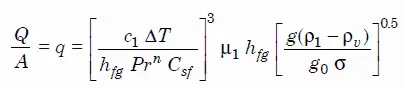
The most widely used correlation for the rate of heat transfer in the nucleate pool boiling was proposed in 1952 by Rohsenow:

Rohsenow correlation

Rohsenow correlation - nucleate boiling

where

  • q – nucleate pool boiling heat flux [W/m2]
  • c1 — specific heat of liquid J/kg K
  • ΔT — excess temperature °C or K
  • hfg  – enthalpy of vaporization, J/kg
  • Pr — Prandtl number of liquid
  • n — experimental constant equal to 1 for water and 1.7 for other fluids
  • Csf — surface fluid factor, for example, water and nickel have a Csf of 0.006
  • μ1 — dynamic viscosity of the liquid kg/m.s
  • g – gravitational acceleration m/s2
  • g0 — force conversion factor kgm/Ns2
  • ρ1 — density of the liquid kg/m3
  • ρv — density of vapour kg/m3
  • σ — surface tension-liquid-vapour interface N/m

As can be seen, ΔT ∝ (q)⅓. This very important proportionality shows increasing ability of interface to transfer heat.

 
References:
Heat Transfer:
  1. Fundamentals of Heat and Mass Transfer, 7th Edition. Theodore L. Bergman, Adrienne S. Lavine, Frank P. Incropera. John Wiley & Sons, Incorporated, 2011. ISBN: 9781118137253.
  2. Heat and Mass Transfer. Yunus A. Cengel. McGraw-Hill Education, 2011. ISBN: 9780071077866.
  3. U.S. Department of Energy, Thermodynamics, Heat Transfer and Fluid Flow. DOE Fundamentals Handbook, Volume 2 of 3. May 2016.

Nuclear and Reactor Physics:

  1. J. R. Lamarsh, Introduction to Nuclear Reactor Theory, 2nd ed., Addison-Wesley, Reading, MA (1983).
  2. J. R. Lamarsh, A. J. Baratta, Introduction to Nuclear Engineering, 3d ed., Prentice-Hall, 2001, ISBN: 0-201-82498-1.
  3. W. M. Stacey, Nuclear Reactor Physics, John Wiley & Sons, 2001, ISBN: 0- 471-39127-1.
  4. Glasstone, Sesonske. Nuclear Reactor Engineering: Reactor Systems Engineering, Springer; 4th edition, 1994, ISBN: 978-0412985317
  5. W.S.C. Williams. Nuclear and Particle Physics. Clarendon Press; 1 edition, 1991, ISBN: 978-0198520467
  6. G.R.Keepin. Physics of Nuclear Kinetics. Addison-Wesley Pub. Co; 1st edition, 1965
  7. Robert Reed Burn, Introduction to Nuclear Reactor Operation, 1988.
  8. U.S. Department of Energy, Nuclear Physics and Reactor Theory. DOE Fundamentals Handbook, Volume 1 and 2. January 1993.
  9. Paul Reuss, Neutron Physics. EDP Sciences, 2008. ISBN: 978-2759800414.

Advanced Reactor Physics:

  1. K. O. Ott, W. A. Bezella, Introductory Nuclear Reactor Statics, American Nuclear Society, Revised edition (1989), 1989, ISBN: 0-894-48033-2.
  2. K. O. Ott, R. J. Neuhold, Introductory Nuclear Reactor Dynamics, American Nuclear Society, 1985, ISBN: 0-894-48029-4.
  3. D. L. Hetrick, Dynamics of Nuclear Reactors, American Nuclear Society, 1993, ISBN: 0-894-48453-2.
  4. E. E. Lewis, W. F. Miller, Computational Methods of Neutron Transport, American Nuclear Society, 1993, ISBN: 0-894-48452-4.

See also:

Boiling and Condensation

We hope, this article, Nucleate Boiling Correlation – Rohsenow Correlation, helps you. If so, give us a like in the sidebar. Main purpose of this website is to help the public to learn some interesting and important information about thermal engineering.
What is McAdams – Thom – Chen’s Correlation – Nucleate Boiling – Definition

McAdams – Thom – Chen’s Correlation – Nucleate Boiling. These correlation may be used for heat transfer calculations in flow boiling (or forced convection boiling). Thermal Engineering

Nucleate Boiling – Flow Boiling

Flow Boiling - Boiling ModesIn flow boiling (or forced convection boiling), fluid flow is forced over a surface by external means such as a pump, as well as by buoyancy effects. Therefore, flow boiling is always accompanied by other convection effects. Conditions depend strongly on geometry, which may involve external flow over heated plates and cylinders or internal (duct) flow. In nuclear reactors, most of boiling regimes are just forced convection boiling. The flow boiling is also classified as either external and internal flow boiling depending on whether the fluid is forced to flow over a heated surface or inside a heated channel.

Internal flow boiling is much more complicated in nature than external flow boiling because there is no free surface for the vapor to escape, and thus both the liquid and the vapor are forced to flow together. The two-phase flow in a tube exhibits different flow boiling regimes, depending on the relative amounts of the liquid and the vapor phases. Therefore internal forced convection boiling is commonly referred to as two-phase flow.

Nucleate Boiling Correlations – Flow Boiling

McAdams Correlation

In fully developed nucleate boiling with saturated coolant, the wall temperature is determined by local heat flux and pressure and is only slightly dependent on the Reynolds number. For subcooled water at absolute pressures between 0.1 – 0.6 MPa, McAdams correlation gives:

nucleate boiling - McAdams Correlation

Thom Correlation

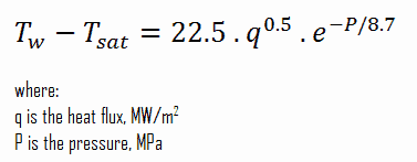
The Thom correlation is for the flow boiling (subcooled or saturated at pressures up to about 20 MPa) under conditions where the nucleate boiling contribution predominates over forced convection. This correlation is useful for rough estimation of expected temperature difference given the heat flux:

nucleate boiling - Thom Correlation

Chen’s Correlation

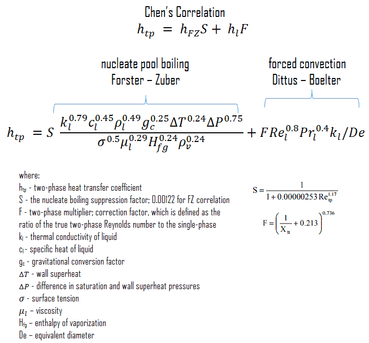
In 1963, Chen proposed the first flow boiling correlation for evaporation in vertical tubes to attain widespread use. Chen’s correlation includes both the heat transfer coefficients due to nucleate boiling as well as forced convective mechanisms. It must be noted, at higher vapor fractions, the heat transfer coefficient varies strongly with flow rate. The flow velocity in a core can be very high causing very high turbulences. This heat transfer mechanism has been referred to as “forced convection evaporation”. No adequate criteria has been established to determine the transition from nucleate boiling to forced convection vaporization. However, a single correlation that is valid for both nucleate boiling and forced convection vaporization has been developed by Chen for saturated boiling conditions and extended to include subcooled boiling by others. Chen proposed a correlation where the heat transfer coefficient is the sum of a forced convection component and a nucleate boiling component. It must be noted, the nucleate pool boiling correlation of Forster and Zuber (1955) is used to calculate the nucleate boiling heat transfer coefficient, hFZ and the turbulent flow correlation of Dittus-Boelter (1930) is used to calculate the liquid-phase convective heat transfer coefficient, hl.

Chens Correlation - Forster-Zuber

The nucleate boiling suppression factor, S, is the ratio of the effective superheat to wall superheat. It accounts for decreased boiling heat transfer because the effective superheat across the boundary layer is less than the superheat based on wall temperature. The two-phase multiplier, F, is a function of the Martinelli parameter χtt.

 
References:
Heat Transfer:
  1. Fundamentals of Heat and Mass Transfer, 7th Edition. Theodore L. Bergman, Adrienne S. Lavine, Frank P. Incropera. John Wiley & Sons, Incorporated, 2011. ISBN: 9781118137253.
  2. Heat and Mass Transfer. Yunus A. Cengel. McGraw-Hill Education, 2011. ISBN: 9780071077866.
  3. U.S. Department of Energy, Thermodynamics, Heat Transfer and Fluid Flow. DOE Fundamentals Handbook, Volume 2 of 3. May 2016.

Nuclear and Reactor Physics:

  1. J. R. Lamarsh, Introduction to Nuclear Reactor Theory, 2nd ed., Addison-Wesley, Reading, MA (1983).
  2. J. R. Lamarsh, A. J. Baratta, Introduction to Nuclear Engineering, 3d ed., Prentice-Hall, 2001, ISBN: 0-201-82498-1.
  3. W. M. Stacey, Nuclear Reactor Physics, John Wiley & Sons, 2001, ISBN: 0- 471-39127-1.
  4. Glasstone, Sesonske. Nuclear Reactor Engineering: Reactor Systems Engineering, Springer; 4th edition, 1994, ISBN: 978-0412985317
  5. W.S.C. Williams. Nuclear and Particle Physics. Clarendon Press; 1 edition, 1991, ISBN: 978-0198520467
  6. G.R.Keepin. Physics of Nuclear Kinetics. Addison-Wesley Pub. Co; 1st edition, 1965
  7. Robert Reed Burn, Introduction to Nuclear Reactor Operation, 1988.
  8. U.S. Department of Energy, Nuclear Physics and Reactor Theory. DOE Fundamentals Handbook, Volume 1 and 2. January 1993.
  9. Paul Reuss, Neutron Physics. EDP Sciences, 2008. ISBN: 978-2759800414.

Advanced Reactor Physics:

  1. K. O. Ott, W. A. Bezella, Introductory Nuclear Reactor Statics, American Nuclear Society, Revised edition (1989), 1989, ISBN: 0-894-48033-2.
  2. K. O. Ott, R. J. Neuhold, Introductory Nuclear Reactor Dynamics, American Nuclear Society, 1985, ISBN: 0-894-48029-4.
  3. D. L. Hetrick, Dynamics of Nuclear Reactors, American Nuclear Society, 1993, ISBN: 0-894-48453-2.
  4. E. E. Lewis, W. F. Miller, Computational Methods of Neutron Transport, American Nuclear Society, 1993, ISBN: 0-894-48452-4.

See also:

Boiling and Condensation

We hope, this article, McAdams – Thom – Chen’s Correlation – Nucleate Boiling, helps you. If so, give us a like in the sidebar. Main purpose of this website is to help the public to learn some interesting and important information about thermal engineering.
What is Condensation – Heat Transfer – Definition

Condensation is the change of the physical state of matter from gas phase into liquid phase, and is the reverse of vaporisation. Condensation – Heat Transfer

Condensation

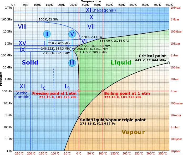
Phase diagram of water
Phase diagram of water.
Source: wikipedia.org CC BY-SA

Similarly as in the previous chapter, in this chapter we will discuss heat transfer with phase change, but in this case we will discuss condensation of gas phase (vapor-to-liquid phase change).

In general, condensation is the change of the physical state of matter from gas phase into liquid phase, and is the reverse of vaporisation. Flow processes associated with condensation on a solid surface are almost a mirror image of those involved in boiling. Condensation occurs when the temperature of a vapor is reduced below its saturation temperature or when the pressure of a vapor is increased above its saturation parameters (see phase diagram of water).

 
Two-phase Fluid Flow
two-phase fluid flowBy definition, multiphase flow is the interactive flow of two or more distinct phases with common interfaces in, say, a conduit. Each phase, representing a volume fraction (or mass fraction) of solid, liquid or gaseous matter, has its own properties, velocity, and temperature.

A multiphase flow can be simultaneous flow of:

  • Materials with different states or phases (e.g. water-steam mixture).
  • Materials with different chemical properties but in the same state or phase (e.g. oil droplets in water).

There are many combinations in industrial processes, but the most common being the simultaneous flow of steam and liquid water (as encountered in steam generators and condensers). In reactor engineering a great deal of study has been performed on the nature of two-phase flow in case of a loss-of-coolant accident (LOCA), which is an accident of importance in reactor safety and in all thermal-hydraulic analyses (DNBR analyses).

Characteristics of Two-phase Fluid Flow

All two-phase flow problems have features which are characteristically different from those found in single-phase problems.

  • In the case of steam and liquid water the density of the two phases differs by a factor of about 1000. Therefore the influence of gravitational body force on multiphase flows is of much greater importance than in the case of single-phase flows.
  • The sound speed changes dramatically for materials undergoing phase change, and can be orders of magnitude different. This significantly influences a flow through an orifice.
  • The relative concentration of different phases is usually a dependent parameter of great importance in multiphase flows, while it is a parameter of no consequence in single-phase flows.
  • The change of phase means flow-induced pressure drops can cause further phase-change (e.g. water can evaporate through an orifice) increasing the relative volume of the gaseous, compressible medium and increasing efflux velocities, unlike single-phase incompressible flow where decreasing of an orifice would decrease efflux velocities.
  • The spatial distribution of the various phases in the flow channel strongly affects the flow behavior.
  • There are many types of instabilities in multiphase flow.
Boiling Point - Saturation
In thermodynamics, the term saturation defines a condition in which a mixture of vapor and liquid can exist together at a given temperature and pressure. The temperature at which vaporization (boiling) starts to occur for a given pressure is called the saturation temperature or boiling point. The pressure at which vaporization (boiling) starts to occur for a given temperature is called the saturation pressure.

When the vapor quality is equal to 0, it is referred to as the saturated liquid state (single-phase). On the other hand, when the vapor quality is equal to 1, it is referred to as the saturated vapor state or dry steam (single-phase). Between these two states, we talk about vapor-liquid mixture or wet steam (two-phase mixture). At constant pressure, an addition of energy does not changes the temperature of the mixture, but the vapor quality and specific volume changes.

dry-steam-saturated-vapor-minFor condensation, latent heat effects associated with the phase change are significant, similarly as for boiling, but in reverse. Note that the enthalpy of condensation (or heat of condensation) is by definition equal to the enthalpy of vaporization with the opposite sign. Latent heat is the amount of heat added to or removed from a substance to produce a change in phase. During vaporisation, this energy breaks down the intermolecular attractive forces, and also must provide the energy necessary to expand the gas (the pΔV work).  When latent heat is added or removed, no temperature change occurs. The enthalpy of vaporization is a function of the pressure at which that transformation takes place.
Latent heat of vaporization - water at 0.1 MPa, 3 MPa, 16 MPa
The heat of vaporization diminishes with increasing pressure, while the boiling point increases. It vanishes completely at a certain point called the critical point.

Latent heat of condensation – water at 0.1 MPa (atmospheric pressure)

hlg = – 2257 kJ/kg

Latent heat of condensation – water at 3 MPa

hlg = – 1795 kJ/kg

Latent heat of condensation – water at 16 MPa (pressure inside a pressurizer)

hlg = – 931 kJ/kg

The heat of condensation diminishes with increasing pressure, while the boiling point increases. It vanishes completely at a certain point called the critical point. Above the critical point, the liquid and vapor phases are indistinguishable, and the substance is called a supercritical fluid.

The change from the liquid to the vapor state due to boiling is sustained by heat transfer from the solid surface; conversely, condensation of a vapor to the liquid state results in heat transfer to the solid surface. Boiling and condensation differ from other forms of convection in that they depend on the latent heat of vaporization, which is very high for common pressures, therefore large amounts of heat can be transferred during boiling and condensation essentially at constant temperature. Heat transfer coefficients, h, associated with boiling and condensation are typically much higher than those encountered in other forms of convection processes that involve a single phase.

Condensation Modes – Types of Condensation

From a practical engineering point of view condensation can be categorized according to several criteria.

In general, three distinct forms of condensation are observed:

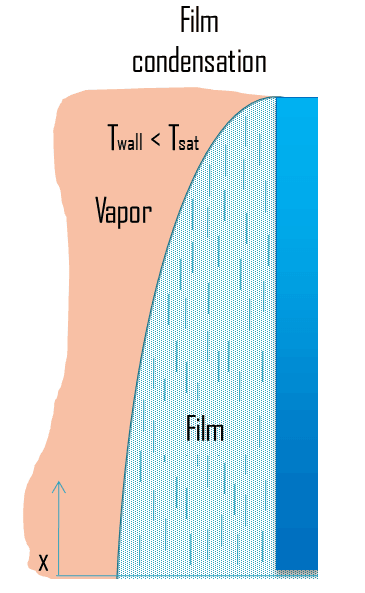
  • Film condensation. In film condensation, the condensate wets the surface and forms a liquid film on the surface that slides down under the influence of gravity. Film condensation results in low heat transfer rates as the film of condensate impedes the heat transfer. The thickness of the film formed depends on many parameters including orientation of the surface, viscosity, rate of condensation etc. The film increases a thermal resistance to heat flow between the surface and the vapour. The rate of heat transfer is reduced because of this resistance.
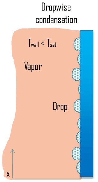
  • Dropwise condensation. In dropwise condensation, the condensed vapor forms droplets on the surface instead of a continuous film. Dropwise condensation can occur when the surface is nonwetting or these droplets are taken away from the surface by external flow or by gravity. The vapour is in direct contact with the surface over most of the area and heat transfer rates are much higher (more than 3 – 10 times higher) as there is very little resistance for heat flow between the vapour and the surface. The droplets develop at nucleation sites (points of surface imperfections such as pit, scratch and cavities), and grow in size as more vapour condenses on its exposed surface. For steam condensers, it is common practice to use surface coatings (silicons, teflons or waxes) that inhibit wetting, and hence stimulate dropwise condensation. But coatings gradually lose their effectiveness due to removal, oxidation etc. In practice no surface is found to continue as nonwetting over any length of time. Since in most engineering applications it is often difficult to maintain this condition, using the value of heat transfer coefficients assuming dropwise condensation for design purposes is not advisable.
  • Direct contact condensation. Direct contact condensation, DCC, occurs when vapor is brought into contact with a cold liquid. As in jet condensers, the cooling water is sprayed on the exhaust steam and there is direct contact between the exhaust steam and cooling water. The process of condensation is very fast and efficient, but here cooling water and condensed steam are mixed up. The advantages of direct contact condensation over the conventional processes using metallic transfer surfaces are due to the relative simplicity of design, less corrosion and scaling problems, lower maintenance costs, higher specific transfer areas, and higher transfer rates. Despite these advantages jet condensers are not usual in thermal power plants especially due to the loss of condensate.
film condensation

___________

dropwise condensation

___________

direct contact condensation

Condensation in Power Plants – Main Condensator

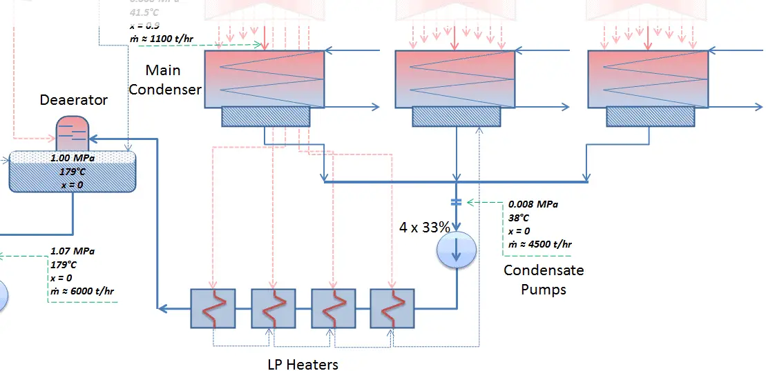
Condenser - LP Heaters - DeaeratorThe main steam condenser (MC) system is designed to condense and deaerate the exhaust steam from the main turbine and provide a heat sink for the turbine bypass system. The exhausted steam from the LP turbines is condensed by passing over tubes containing water from the cooling system. There is a main condenser unit under each LP turbine, usually below the turbine with its axis perpendicular to the turbine axis. Since nuclear power plants usually contain also an auxiliary condenser (e.g. to condense steam from steam driven feedwater pumps), engineers use the term “main condenser“.

See also: Main Condenser

The condenser must maintain a sufficient low vacuum in order to increase the power plant efficiency. The vacuum pumps maintain a sufficient vacuum in the condenser by extracting air and uncondensed gases. The lowest feasible condenser pressure is the saturation pressure corresponding to the ambient temperature (e.g. absolute pressure of 0.008 MPa, which corresponds to 41.5°C). Note that, there is always a temperature difference between (around ΔT = 14°C) the condenser temperature and the ambient temperature, which originates from finite size and efficiency of condensers. Since neither the condenser is 100% efficient heat exchanger, there is always a temperature difference between the saturation temperature (secondary side) and the temperature of the coolant in the cooling system. Moreover, there is a design inefficiciency, which decreases the overall efficiency of the turbine. Ideally the steam exhausted into the condenser would have no subcooling. But real condensers are designed to subcool the liquid by a few degrees of Celsius in order to avoid the suction cavitation in the condensate pumps.

The steam condensers are broadly classified into two types:

  • Surface condensers (or non-mixing type condensers). In surface condensers, there is no direct contact between the exhaust steam and the cooling water.
  • Jet condensers (or mixing type condensers). In jet condensers there is direct contact between the exhaust steam and cooling water.

&nbsp;

Condensation in Pressurizer

Extensive vs. intensive thermodynamic properties
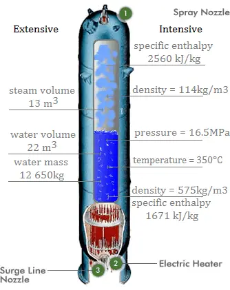
Extensive and intensive properties of medium in the pressurizer.

A pressurizer is a component of a pressurized water reactor. Pressure in the primary circuit of PWRs is maintained by a pressurizer, a separate vessel that is connected to the primary circuit (hot leg) and partially filled with water which is heated to the saturation temperature (boiling point) for the desired pressure by submerged electrical heaters. Temperature in the pressurizer can be maintained at 350 °C (662 °F), which gives a subcooling margin (the difference between the pressurizer temperature and the highest temperature in the reactor core) of 30 °C. Subcooling margin is very important safety parameter of PWRs, since the boiling in the reactor core must be excluded. The basic design of the pressurized water reactor includes such requirement that the coolant (water) in the reactor coolant system must not boil. To achieve this, the coolant in the reactor coolant system is maintained at a pressure sufficiently high that boiling does not occur at the coolant temperatures experienced while the plant is operating or in an analyzed transient.

Functions

Pressure in the pressurizer is controlled by varying the temperature of the coolant in the pressurizer. For these purposes two systems are installed. Water spray system and electrical heaters system. Volume of the pressurizer (tens of cubic meters) is filled with water on saturation parameters and steam. The water spray system (relatively cool water – from cold leg) can decrease the pressure in the vessel by condensing the steam on water droplets sprayed in the vessel. Since vapor is brought into contact with a cold liquid, in this case, we are talking about direct contact condensation. On the other hand the submerged electrical heaters are designed to increase the pressure by evaporation the water in the vessel. Water pressure in a closed system tracks water temperature directly; as the temperature goes up, pressure goes up.

Condensation in Containment Building

In case of Design Basis Accidents such as  the Large Break Loss of Coolant Accident (LBLOCA) the pressure increase is usually significant and active containment systems (pressure-suppression systems) must be available in order to maintain the integrity (to keep the pressure and temperature under certain limits) of the containment building.

Pressure-suppression systems are critical to safety and greatly affect the size of containment. Suppression refers to condensing the steamafter a major break has released it from the cooling system. There are many designs of suppression systems around the world.

Most of Pressurized Water Reactors (PWRs) containments use two stage pressure-suppression systems:

  • Fan Cooler System. This system circulates air through heat exchangers and filters to provide the cooling of containment atmosphere. Since this system is not sufficient for suppression during severe loss of coolant accidents, the containment spray system must be available as the secondary active pressure-suppression system.
  • Containment Spray System. This system consist usually from three elements:
    • Spray System Pump
    • Spray System Tank
    • Spray System Rings and Nozzles

When pressure increase inside the containment is indicated, thecontainment spray system is automatically started and the pumps (usually with 3×100% redundancy) take a suction from the tank (refueling water storage tank can be also used) and pump the water into spray nozzles located in the upper part of the containment. The water droplets, being cooler than the steam, will remove heat from the steam, which will cause the steam to condense. This will cause a reduction in the pressure of the building and will also reduce the temperature of the containment atmosphere. The spray system usually contains extra chemical additives dissolved in the tank to enhance the removal of particular radionuclides from the containment atmosphere. Especially radioiodine, which is of particular importance, can be effectively bonded to potassium hydroxide or sodium hydroxide.

Most of Boiling Water Reactors (BWR) containments use pressure-suppression pools in order to maintain the integrity of the containment building. The major containment designs are the Mark I, Mark II and the Mark III. The Mark I and Mark II containments consist of two main parts:

  • Drywell. A drywell houses the reactor coolant system.
  • Wetwell. A wetwell is a suppression chamber, which stores a large body of water and therefore it is commonly called as the suppression pool.

Water spray systems are usually installed in both the drywell and the wetwell. The Mark III design consists of a primary containment and a drywell.

Containment buildings and containment  pressure-suppression systems vary widely depending on certain reactor design. In some cases really unique technologies can be installed. For example, the containment building of Loviisa NPP uses two ice condensers as the pressure-suppression system.

 
References:
Heat Transfer:
  1. Fundamentals of Heat and Mass Transfer, 7th Edition. Theodore L. Bergman, Adrienne S. Lavine, Frank P. Incropera. John Wiley & Sons, Incorporated, 2011. ISBN: 9781118137253.
  2. Heat and Mass Transfer. Yunus A. Cengel. McGraw-Hill Education, 2011. ISBN: 9780071077866.
  3. U.S. Department of Energy, Thermodynamics, Heat Transfer and Fluid Flow. DOE Fundamentals Handbook, Volume 2 of 3. May 2016.

Nuclear and Reactor Physics:

  1. J. R. Lamarsh, Introduction to Nuclear Reactor Theory, 2nd ed., Addison-Wesley, Reading, MA (1983).
  2. J. R. Lamarsh, A. J. Baratta, Introduction to Nuclear Engineering, 3d ed., Prentice-Hall, 2001, ISBN: 0-201-82498-1.
  3. W. M. Stacey, Nuclear Reactor Physics, John Wiley & Sons, 2001, ISBN: 0- 471-39127-1.
  4. Glasstone, Sesonske. Nuclear Reactor Engineering: Reactor Systems Engineering, Springer; 4th edition, 1994, ISBN: 978-0412985317
  5. W.S.C. Williams. Nuclear and Particle Physics. Clarendon Press; 1 edition, 1991, ISBN: 978-0198520467
  6. G.R.Keepin. Physics of Nuclear Kinetics. Addison-Wesley Pub. Co; 1st edition, 1965
  7. Robert Reed Burn, Introduction to Nuclear Reactor Operation, 1988.
  8. U.S. Department of Energy, Nuclear Physics and Reactor Theory. DOE Fundamentals Handbook, Volume 1 and 2. January 1993.
  9. Paul Reuss, Neutron Physics. EDP Sciences, 2008. ISBN: 978-2759800414.

Advanced Reactor Physics:

  1. K. O. Ott, W. A. Bezella, Introductory Nuclear Reactor Statics, American Nuclear Society, Revised edition (1989), 1989, ISBN: 0-894-48033-2.
  2. K. O. Ott, R. J. Neuhold, Introductory Nuclear Reactor Dynamics, American Nuclear Society, 1985, ISBN: 0-894-48029-4.
  3. D. L. Hetrick, Dynamics of Nuclear Reactors, American Nuclear Society, 1993, ISBN: 0-894-48453-2.
  4. E. E. Lewis, W. F. Miller, Computational Methods of Neutron Transport, American Nuclear Society, 1993, ISBN: 0-894-48452-4.

See also:

Boiling and Condensation

We hope, this article, Condensation – Heat Transfer, helps you. If so, give us a like in the sidebar. Main purpose of this website is to help the public to learn some interesting and important information about thermal engineering.
What is Latent Heat of Condensation – Enthalpy of Condensation – Definition

For condensation, latent heat effects associated with the phase change are significant, similarly as for boiling, but in reverse. Latent Heat of Condensation – Enthalpy of Condensation
dry-steam-saturated-vapor-minFor condensation, latent heat effects associated with the phase change are significant, similarly as for boiling, but in reverse. Note that the enthalpy of condensation (or heat of condensation) is by definition equal to the enthalpy of vaporization with the opposite sign. Latent heat is the amount of heat added to or removed from a substance to produce a change in phase. During vaporisation, this energy breaks down the intermolecular attractive forces, and also must provide the energy necessary to expand the gas (the pΔV work).  When latent heat is added or removed, no temperature change occurs. The enthalpy of vaporization is a function of the pressure at which that transformation takes place.
Latent heat of vaporization - water at 0.1 MPa, 3 MPa, 16 MPa
The heat of vaporization diminishes with increasing pressure, while the boiling point increases. It vanishes completely at a certain point called the critical point.

Latent heat of condensation – water at 0.1 MPa (atmospheric pressure)

hlg = – 2257 kJ/kg

Latent heat of condensation – water at 3 MPa

hlg = – 1795 kJ/kg

Latent heat of condensation – water at 16 MPa (pressure inside a pressurizer)

hlg = – 931 kJ/kg

The heat of condensation diminishes with increasing pressure, while the boiling point increases. It vanishes completely at a certain point called the critical point. Above the critical point, the liquid and vapor phases are indistinguishable, and the substance is called a supercritical fluid.

The heat of condensation is the heat released to completely condendse a unit of saturated vapor and it equal to – hlg =hl – hg.

The heat that is necessary to melt (or freeze) a unit mass at the substance at constant pressure is the heat of fusion and is equal to hsl = hl − hs, where hs is the enthalpy of saturated solid and hl is the enthalpy of saturated liquid.

Phase changes - enthalpy of vaporization
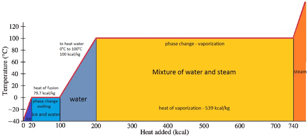
Latent heat of vaporization – water at 0.1 MPa. Dominant part of heat absorbed.
 
References:
Heat Transfer:
  1. Fundamentals of Heat and Mass Transfer, 7th Edition. Theodore L. Bergman, Adrienne S. Lavine, Frank P. Incropera. John Wiley & Sons, Incorporated, 2011. ISBN: 9781118137253.
  2. Heat and Mass Transfer. Yunus A. Cengel. McGraw-Hill Education, 2011. ISBN: 9780071077866.
  3. U.S. Department of Energy, Thermodynamics, Heat Transfer and Fluid Flow. DOE Fundamentals Handbook, Volume 2 of 3. May 2016.

Nuclear and Reactor Physics:

  1. J. R. Lamarsh, Introduction to Nuclear Reactor Theory, 2nd ed., Addison-Wesley, Reading, MA (1983).
  2. J. R. Lamarsh, A. J. Baratta, Introduction to Nuclear Engineering, 3d ed., Prentice-Hall, 2001, ISBN: 0-201-82498-1.
  3. W. M. Stacey, Nuclear Reactor Physics, John Wiley & Sons, 2001, ISBN: 0- 471-39127-1.
  4. Glasstone, Sesonske. Nuclear Reactor Engineering: Reactor Systems Engineering, Springer; 4th edition, 1994, ISBN: 978-0412985317
  5. W.S.C. Williams. Nuclear and Particle Physics. Clarendon Press; 1 edition, 1991, ISBN: 978-0198520467
  6. G.R.Keepin. Physics of Nuclear Kinetics. Addison-Wesley Pub. Co; 1st edition, 1965
  7. Robert Reed Burn, Introduction to Nuclear Reactor Operation, 1988.
  8. U.S. Department of Energy, Nuclear Physics and Reactor Theory. DOE Fundamentals Handbook, Volume 1 and 2. January 1993.
  9. Paul Reuss, Neutron Physics. EDP Sciences, 2008. ISBN: 978-2759800414.

Advanced Reactor Physics:

  1. K. O. Ott, W. A. Bezella, Introductory Nuclear Reactor Statics, American Nuclear Society, Revised edition (1989), 1989, ISBN: 0-894-48033-2.
  2. K. O. Ott, R. J. Neuhold, Introductory Nuclear Reactor Dynamics, American Nuclear Society, 1985, ISBN: 0-894-48029-4.
  3. D. L. Hetrick, Dynamics of Nuclear Reactors, American Nuclear Society, 1993, ISBN: 0-894-48453-2.
  4. E. E. Lewis, W. F. Miller, Computational Methods of Neutron Transport, American Nuclear Society, 1993, ISBN: 0-894-48452-4.

See also:

Boiling and Condensation

We hope, this article, Latent Heat of Condensation – Enthalpy of Condensation, helps you. If so, give us a like in the sidebar. Main purpose of this website is to help the public to learn some interesting and important information about thermal engineering.
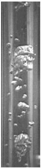
What is Condensation Mode – Types of Condensation – Definition

Condensation Modes – Types of Condensation. From a practical engineering point of view condensation can be categorized according to several criteria. Thermal Engineering

Condensation Modes – Types of Condensation

From a practical engineering point of view condensation can be categorized according to several criteria.

In general, three distinct forms of condensation are observed:

  • Film condensation. In film condensation, the condensate wets the surface and forms a liquid film on the surface that slides down under the influence of gravity. Film condensation results in low heat transfer rates as the film of condensate impedes the heat transfer. The thickness of the film formed depends on many parameters including orientation of the surface, viscosity, rate of condensation etc. The film increases a thermal resistance to heat flow between the surface and the vapour. The rate of heat transfer is reduced because of this resistance.
  • Dropwise condensation. In dropwise condensation, the condensed vapor forms droplets on the surface instead of a continuous film. Dropwise condensation can occur when the surface is nonwetting or these droplets are taken away from the surface by external flow or by gravity. The vapour is in direct contact with the surface over most of the area and heat transfer rates are much higher (more than 3 – 10 times higher) as there is very little resistance for heat flow between the vapour and the surface. The droplets develop at nucleation sites (points of surface imperfections such as pit, scratch and cavities), and grow in size as more vapour condenses on its exposed surface. For steam condensers, it is common practice to use surface coatings (silicons, teflons or waxes) that inhibit wetting, and hence stimulate dropwise condensation. But coatings gradually lose their effectiveness due to removal, oxidation etc. In practice no surface is found to continue as nonwetting over any length of time. Since in most engineering applications it is often difficult to maintain this condition, using the value of heat transfer coefficients assuming dropwise condensation for design purposes is not advisable.
  • Direct contact condensation. Direct contact condensation, DCC, occurs when vapor is brought into contact with a cold liquid. As in jet condensers, the cooling water is sprayed on the exhaust steam and there is direct contact between the exhaust steam and cooling water. The process of condensation is very fast and efficient, but here cooling water and condensed steam are mixed up. The advantages of direct contact condensation over the conventional processes using metallic transfer surfaces are due to the relative simplicity of design, less corrosion and scaling problems, lower maintenance costs, higher specific transfer areas, and higher transfer rates. Despite these advantages jet condensers are not usual in thermal power plants especially due to the loss of condensate.
film condensation

___________

dropwise condensation

___________

direct contact condensation

 
References:
Heat Transfer:
  1. Fundamentals of Heat and Mass Transfer, 7th Edition. Theodore L. Bergman, Adrienne S. Lavine, Frank P. Incropera. John Wiley & Sons, Incorporated, 2011. ISBN: 9781118137253.
  2. Heat and Mass Transfer. Yunus A. Cengel. McGraw-Hill Education, 2011. ISBN: 9780071077866.
  3. U.S. Department of Energy, Thermodynamics, Heat Transfer and Fluid Flow. DOE Fundamentals Handbook, Volume 2 of 3. May 2016.

Nuclear and Reactor Physics:

  1. J. R. Lamarsh, Introduction to Nuclear Reactor Theory, 2nd ed., Addison-Wesley, Reading, MA (1983).
  2. J. R. Lamarsh, A. J. Baratta, Introduction to Nuclear Engineering, 3d ed., Prentice-Hall, 2001, ISBN: 0-201-82498-1.
  3. W. M. Stacey, Nuclear Reactor Physics, John Wiley & Sons, 2001, ISBN: 0- 471-39127-1.
  4. Glasstone, Sesonske. Nuclear Reactor Engineering: Reactor Systems Engineering, Springer; 4th edition, 1994, ISBN: 978-0412985317
  5. W.S.C. Williams. Nuclear and Particle Physics. Clarendon Press; 1 edition, 1991, ISBN: 978-0198520467
  6. G.R.Keepin. Physics of Nuclear Kinetics. Addison-Wesley Pub. Co; 1st edition, 1965
  7. Robert Reed Burn, Introduction to Nuclear Reactor Operation, 1988.
  8. U.S. Department of Energy, Nuclear Physics and Reactor Theory. DOE Fundamentals Handbook, Volume 1 and 2. January 1993.
  9. Paul Reuss, Neutron Physics. EDP Sciences, 2008. ISBN: 978-2759800414.

Advanced Reactor Physics:

  1. K. O. Ott, W. A. Bezella, Introductory Nuclear Reactor Statics, American Nuclear Society, Revised edition (1989), 1989, ISBN: 0-894-48033-2.
  2. K. O. Ott, R. J. Neuhold, Introductory Nuclear Reactor Dynamics, American Nuclear Society, 1985, ISBN: 0-894-48029-4.
  3. D. L. Hetrick, Dynamics of Nuclear Reactors, American Nuclear Society, 1993, ISBN: 0-894-48453-2.
  4. E. E. Lewis, W. F. Miller, Computational Methods of Neutron Transport, American Nuclear Society, 1993, ISBN: 0-894-48452-4.

See also:

Boiling and Condensation

We hope, this article, Condensation Mode – Types of Condensation, helps you. If so, give us a like in the sidebar. Main purpose of this website is to help the public to learn some interesting and important information about thermal engineering.
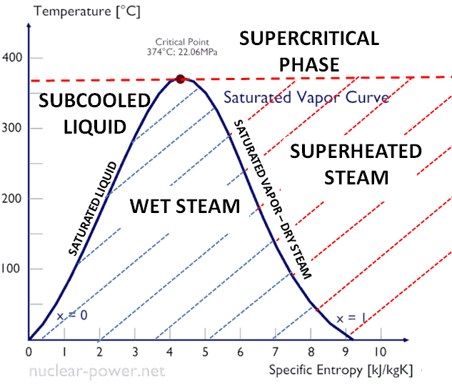
What is Film Condensation – Definition

In film condensation, the condensate wets the surface and forms a liquid film on the surface that slides down under the influence of gravity. Film condensation. Thermal Engineering

Film Condensation

Phase diagram of water
Phase diagram of water.
Source: wikipedia.org CC BY-SA

Similarly as in the previous chapter, in this chapter we will discuss heat transfer with phase change, but in this case we will discuss condensation of gas phase (vapor-to-liquid phase change).

In general, condensation is the change of the physical state of matter from gas phase into liquid phase, and is the reverse of vaporisation. Flow processes associated with condensation on a solid surface are almost a mirror image of those involved in boiling. Condensation occurs when the temperature of a vapor is reduced below its saturation temperature or when the pressure of a vapor is increased above its saturation parameters (see phase diagram of water).

film condensationIn film condensation, the condensate wets the surface and forms a liquid film on the surface that slides down under the influence of gravity. Film condensation results in low heat transfer rates as the film of condensate impedes the heat transfer. The thickness of the film formed depends on many parameters including orientation of the surface, viscosity, rate of condensation etc. The film increases a thermal resistance to heat flow between the surface and the vapour. The rate of heat transfer is reduced because of this resistance.

Condensation in Power Plants – Main Condensator

Condenser - LP Heaters - DeaeratorThe main steam condenser (MC) system is designed to condense and deaerate the exhaust steam from the main turbine and provide a heat sink for the turbine bypass system. The exhausted steam from the LP turbines is condensed by passing over tubes containing water from the cooling system. There is a main condenser unit under each LP turbine, usually below the turbine with its axis perpendicular to the turbine axis. Since nuclear power plants usually contain also an auxiliary condenser (e.g. to condense steam from steam driven feedwater pumps), engineers use the term “main condenser“.

See also: Main Condenser

The condenser must maintain a sufficient low vacuum in order to increase the power plant efficiency. The vacuum pumps maintain a sufficient vacuum in the condenser by extracting air and uncondensed gases. The lowest feasible condenser pressure is the saturation pressure corresponding to the ambient temperature (e.g. absolute pressure of 0.008 MPa, which corresponds to 41.5°C). Note that, there is always a temperature difference between (around ΔT = 14°C) the condenser temperature and the ambient temperature, which originates from finite size and efficiency of condensers. Since neither the condenser is 100% efficient heat exchanger, there is always a temperature difference between the saturation temperature (secondary side) and the temperature of the coolant in the cooling system. Moreover, there is a design inefficiciency, which decreases the overall efficiency of the turbine. Ideally the steam exhausted into the condenser would have no subcooling. But real condensers are designed to subcool the liquid by a few degrees of Celsius in order to avoid the suction cavitation in the condensate pumps.

The steam condensers are broadly classified into two types:

  • Surface condensers (or non-mixing type condensers). In surface condensers, there is no direct contact between the exhaust steam and the cooling water.
  • Jet condensers (or mixing type condensers). In jet condensers there is direct contact between the exhaust steam and cooling water.
 
References:
Heat Transfer:
  1. Fundamentals of Heat and Mass Transfer, 7th Edition. Theodore L. Bergman, Adrienne S. Lavine, Frank P. Incropera. John Wiley & Sons, Incorporated, 2011. ISBN: 9781118137253.
  2. Heat and Mass Transfer. Yunus A. Cengel. McGraw-Hill Education, 2011. ISBN: 9780071077866.
  3. U.S. Department of Energy, Thermodynamics, Heat Transfer and Fluid Flow. DOE Fundamentals Handbook, Volume 2 of 3. May 2016.

Nuclear and Reactor Physics:

  1. J. R. Lamarsh, Introduction to Nuclear Reactor Theory, 2nd ed., Addison-Wesley, Reading, MA (1983).
  2. J. R. Lamarsh, A. J. Baratta, Introduction to Nuclear Engineering, 3d ed., Prentice-Hall, 2001, ISBN: 0-201-82498-1.
  3. W. M. Stacey, Nuclear Reactor Physics, John Wiley & Sons, 2001, ISBN: 0- 471-39127-1.
  4. Glasstone, Sesonske. Nuclear Reactor Engineering: Reactor Systems Engineering, Springer; 4th edition, 1994, ISBN: 978-0412985317
  5. W.S.C. Williams. Nuclear and Particle Physics. Clarendon Press; 1 edition, 1991, ISBN: 978-0198520467
  6. G.R.Keepin. Physics of Nuclear Kinetics. Addison-Wesley Pub. Co; 1st edition, 1965
  7. Robert Reed Burn, Introduction to Nuclear Reactor Operation, 1988.
  8. U.S. Department of Energy, Nuclear Physics and Reactor Theory. DOE Fundamentals Handbook, Volume 1 and 2. January 1993.
  9. Paul Reuss, Neutron Physics. EDP Sciences, 2008. ISBN: 978-2759800414.

Advanced Reactor Physics:

  1. K. O. Ott, W. A. Bezella, Introductory Nuclear Reactor Statics, American Nuclear Society, Revised edition (1989), 1989, ISBN: 0-894-48033-2.
  2. K. O. Ott, R. J. Neuhold, Introductory Nuclear Reactor Dynamics, American Nuclear Society, 1985, ISBN: 0-894-48029-4.
  3. D. L. Hetrick, Dynamics of Nuclear Reactors, American Nuclear Society, 1993, ISBN: 0-894-48453-2.
  4. E. E. Lewis, W. F. Miller, Computational Methods of Neutron Transport, American Nuclear Society, 1993, ISBN: 0-894-48452-4.

See also:

Boiling and Condensation

We hope, this article, Film Condensation, helps you. If so, give us a like in the sidebar. Main purpose of this website is to help the public to learn some interesting and important information about thermal engineering.
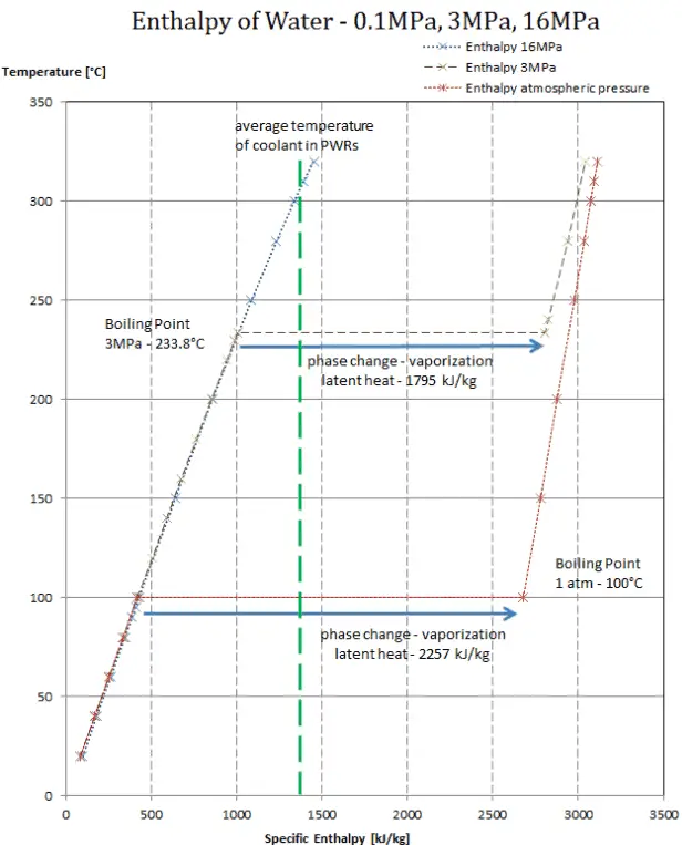
What is Dropwise condensation – Definition

Dropwise condensation. In dropwise condensation, the condensed vapor forms droplets on the surface instead of a continuous film. Thermal Engineering

Dropwise Condensation

Phase diagram of water
Phase diagram of water.
Source: wikipedia.org CC BY-SA

Similarly as in the previous chapter, in this chapter we will discuss heat transfer with phase change, but in this case we will discuss condensation of gas phase (vapor-to-liquid phase change).

In general, condensation is the change of the physical state of matter from gas phase into liquid phase, and is the reverse of vaporisation. Flow processes associated with condensation on a solid surface are almost a mirror image of those involved in boiling. Condensation occurs when the temperature of a vapor is reduced below its saturation temperature or when the pressure of a vapor is increased above its saturation parameters (see phase diagram of water).

dropwise condensationIn dropwise condensation, the condensed vapor forms droplets on the surface instead of a continuous film. Dropwise condensation can occur when the surface is nonwetting or these droplets are taken away from the surface by external flow or by gravity. The vapour is in direct contact with the surface over most of the area and heat transfer rates are much higher (more than 3 – 10 times higher) as there is very little resistance for heat flow between the vapour and the surface. The droplets develop at nucleation sites (points of surface imperfections such as pit, scratch and cavities), and grow in size as more vapour condenses on its exposed surface. For steam condensers, it is common practice to use surface coatings (silicons, teflons or waxes) that inhibit wetting, and hence stimulate dropwise condensation. But coatings gradually lose their effectiveness due to removal, oxidation etc. In practice no surface is found to continue as nonwetting over any length of time. Since in most engineering applications it is often difficult to maintain this condition, using the value of heat transfer coefficients assuming dropwise condensation for design purposes is not advisable.

 
References:
Heat Transfer:
  1. Fundamentals of Heat and Mass Transfer, 7th Edition. Theodore L. Bergman, Adrienne S. Lavine, Frank P. Incropera. John Wiley & Sons, Incorporated, 2011. ISBN: 9781118137253.
  2. Heat and Mass Transfer. Yunus A. Cengel. McGraw-Hill Education, 2011. ISBN: 9780071077866.
  3. U.S. Department of Energy, Thermodynamics, Heat Transfer and Fluid Flow. DOE Fundamentals Handbook, Volume 2 of 3. May 2016.

Nuclear and Reactor Physics:

  1. J. R. Lamarsh, Introduction to Nuclear Reactor Theory, 2nd ed., Addison-Wesley, Reading, MA (1983).
  2. J. R. Lamarsh, A. J. Baratta, Introduction to Nuclear Engineering, 3d ed., Prentice-Hall, 2001, ISBN: 0-201-82498-1.
  3. W. M. Stacey, Nuclear Reactor Physics, John Wiley & Sons, 2001, ISBN: 0- 471-39127-1.
  4. Glasstone, Sesonske. Nuclear Reactor Engineering: Reactor Systems Engineering, Springer; 4th edition, 1994, ISBN: 978-0412985317
  5. W.S.C. Williams. Nuclear and Particle Physics. Clarendon Press; 1 edition, 1991, ISBN: 978-0198520467
  6. G.R.Keepin. Physics of Nuclear Kinetics. Addison-Wesley Pub. Co; 1st edition, 1965
  7. Robert Reed Burn, Introduction to Nuclear Reactor Operation, 1988.
  8. U.S. Department of Energy, Nuclear Physics and Reactor Theory. DOE Fundamentals Handbook, Volume 1 and 2. January 1993.
  9. Paul Reuss, Neutron Physics. EDP Sciences, 2008. ISBN: 978-2759800414.

Advanced Reactor Physics:

  1. K. O. Ott, W. A. Bezella, Introductory Nuclear Reactor Statics, American Nuclear Society, Revised edition (1989), 1989, ISBN: 0-894-48033-2.
  2. K. O. Ott, R. J. Neuhold, Introductory Nuclear Reactor Dynamics, American Nuclear Society, 1985, ISBN: 0-894-48029-4.
  3. D. L. Hetrick, Dynamics of Nuclear Reactors, American Nuclear Society, 1993, ISBN: 0-894-48453-2.
  4. E. E. Lewis, W. F. Miller, Computational Methods of Neutron Transport, American Nuclear Society, 1993, ISBN: 0-894-48452-4.

See also:

Boiling and Condensation

We hope, this article, Dropwise condensation, helps you. If so, give us a like in the sidebar. Main purpose of this website is to help the public to learn some interesting and important information about thermal engineering.