Facebook Instagram Youtube Twitter

What is Thermal Column – Definition

Another important convection current, which is formed in the atmosphere is a thermal column. Thermal column is a column of rising air in the lower altitudes of Earth’s atmosphere, a form of atmospheric updraft.

Convection Currents – Thermal Column

thermal column - convection currents
Source: wikipedia.org License: CC BY 2.5

Another important convection current, which is formed in the atmosphere is a thermal column. Thermal column is a column of rising air in the lower altitudes of Earth’s atmosphere, a form of atmospheric updraft. Thermal columns are created by the uneven heating of the Earth’s surface from solar radiation, and are an example of atmospheric natural convection.

The Sun warms the ground, which in turn warms the air directly above it. The warmer air nearer to the surface expands, becoming less dense than the surrounding air. The lighter air rises and cools due to its expansion in the lower pressure at higher altitudes. It stops rising when it has cooled to the same temperature as the surrounding air. Dark earth, urban areas, and roadways are good sources of thermal columns.

Creation of Convection Currents

Creation of convection currents is based on three physical assumptions:

  • Presence of heat source. Heat source is required, because convection currents are generated by density differences in the fluid occurring due to temperature gradients. In natural convection, fluid surrounding a heat source receives heat and by thermal expansion becomes less dense and rises. Thermal expansion of the fluid plays a crucial role. In other words, heavier (more dense) components will fall, while lighter (less dense) components rise, leading to bulk fluid movement.
  • Presence of proper acceleration. Natural convection can only occur in a gravitational field or in the presence of another proper acceleration, such as acceleration, centrifugal force and Coriolis force. Natural convection essentially does not operate in the orbit of Earth. For example, in the orbiting International Space Station, other heat transfer mechanisms are required to prevent electronic components from overheating.
  • Proper geometry. The presence and magnitude of natural convection also depend on the geometry of the problem. The presence of a fluid density gradient in a gravitational field does not ensure the existence of natural convection currents. This problem is illustrated in the following figure, where a fluid is enclosed by two large, horizontal plates of different temperature (Tupper ≠ Tlower).
    • In case A the temperature of the lower plate is higher than the temperature of the upper plate. In this case, the density decreases in the direction of the gravitational force. This geometry induces fluid circulation and heat transfer occurs via natural circulation. The heavier fluid will descend, being warmed in the process, while the lighter fluid will rise, cooling as it moves.
    • In case B the temperature of the lower plate is lower than the temperature of the upper plate. In this case, the density increases in the direction of the gravitational force. This geometry leads to stable conditions, stable temperature gradient and does not induce fluid circulation. Heat transfer occurs solely via thermal conduction.
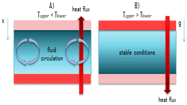
natural circulation - geometry

 
References:
Heat Transfer:
  1. Fundamentals of Heat and Mass Transfer, 7th Edition. Theodore L. Bergman, Adrienne S. Lavine, Frank P. Incropera. John Wiley & Sons, Incorporated, 2011. ISBN: 9781118137253.
  2. Heat and Mass Transfer. Yunus A. Cengel. McGraw-Hill Education, 2011. ISBN: 9780071077866.
  3. U.S. Department of Energy, Thermodynamics, Heat Transfer and Fluid Flow. DOE Fundamentals Handbook, Volume 2 of 3. May 2016.

Nuclear and Reactor Physics:

  1. J. R. Lamarsh, Introduction to Nuclear Reactor Theory, 2nd ed., Addison-Wesley, Reading, MA (1983).
  2. J. R. Lamarsh, A. J. Baratta, Introduction to Nuclear Engineering, 3d ed., Prentice-Hall, 2001, ISBN: 0-201-82498-1.
  3. W. M. Stacey, Nuclear Reactor Physics, John Wiley & Sons, 2001, ISBN: 0- 471-39127-1.
  4. Glasstone, Sesonske. Nuclear Reactor Engineering: Reactor Systems Engineering, Springer; 4th edition, 1994, ISBN: 978-0412985317
  5. W.S.C. Williams. Nuclear and Particle Physics. Clarendon Press; 1 edition, 1991, ISBN: 978-0198520467
  6. G.R.Keepin. Physics of Nuclear Kinetics. Addison-Wesley Pub. Co; 1st edition, 1965
  7. Robert Reed Burn, Introduction to Nuclear Reactor Operation, 1988.
  8. U.S. Department of Energy, Nuclear Physics and Reactor Theory. DOE Fundamentals Handbook, Volume 1 and 2. January 1993.
  9. Paul Reuss, Neutron Physics. EDP Sciences, 2008. ISBN: 978-2759800414.

Advanced Reactor Physics:

  1. K. O. Ott, W. A. Bezella, Introductory Nuclear Reactor Statics, American Nuclear Society, Revised edition (1989), 1989, ISBN: 0-894-48033-2.
  2. K. O. Ott, R. J. Neuhold, Introductory Nuclear Reactor Dynamics, American Nuclear Society, 1985, ISBN: 0-894-48029-4.
  3. D. L. Hetrick, Dynamics of Nuclear Reactors, American Nuclear Society, 1993, ISBN: 0-894-48453-2.
  4. E. E. Lewis, W. F. Miller, Computational Methods of Neutron Transport, American Nuclear Society, 1993, ISBN: 0-894-48452-4.

See also:

Convection Currents

We hope, this article, Thermal Column, helps you. If so, give us a like in the sidebar. Main purpose of this website is to help the public to learn some interesting and important information about thermal engineering.
What is Forced Convection – Definition

Forced Convection. In this chapter we consider convection transfer in fluid flows that originate from an external forcing condition – forced convection. Thermal Engineering

Forced Convection

As was written, convection takes place through advection, diffusion or both. In this chapter we consider convection transfer in fluid flows that originate from an external forcing condition – forced convection.

Newton’s Law of Cooling

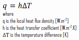
Despite the complexity of convection, the rate of convection heat transfer is observed to be proportional to the temperature difference and is conveniently expressed by Newton’s law of cooling, which states that:

The rate of heat loss of a body is directly proportional to the difference in the temperatures between the body and its surroundings provided the temperature difference is small and the nature of radiating surface remains same.

newton's law of cooling - convection equation

Note that, ΔT is given by the surface or wall temperature, Twall and the bulk temperature, T∞, which is the temperature of the fluid sufficiently far from the surface.

Forced Convection – Dittus-Boelter Equation

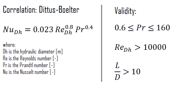
For fully developed (hydrodynamically and thermally) turbulent flow in a smooth circular tube, the local Nusselt number may be obtained from the well-known Dittus-Boelter equation. The Dittus–Boelter equation is easy to solve but is less accurate when there is a large temperature difference across the fluid and is less accurate for rough tubes (many commercial applications), since it is tailored to smooth tubes.

Dittus-Boelter Equation - Formula

The Dittus-Boelter correlation may be used for small to moderate temperature differences, Twall – Tavg, with all properties evaluated at an averaged temperature Tavg.

For flows characterized by large property variations, the corrections (e.g. a viscosity correction factor μ/μwall) must be taken into account, for example, as Sieder and Tate recommend.

Combined Forced and Natural Convection

natural convection vs forced convectionAs was written, convection takes place through advection, diffusion or both. In preceding chapters we considered convection transfer in fluid flows that originate from an external forcing condition – forced convection. In this chapter, we consider natural convection, where any fluid motion occurs by natural means such as buoyancy. In fact, there are flow regimes, in which we have to consider both forcing mechanisms. When flow velocities are low, natural convection will also contribute in addition to forced convection. Whether or not free convection is significant for heat transfer, it can be checked using the following criteria:

  • If Gr/Re2 >> 1 free convection prevails
  • If Gr/Re2 << 1 forced convection prevails
  • If Gr/Re2 ≈ 1 both should be considered

The effect of buoyancy on heat transfer in a forced flow is strongly influenced by the direction of the buoyancy force relative to that of the flow. Natural convection may help or hurt forced convection heat transfer, depending on the relative directions of buoyancy-induced and the forced convection motions. Three special cases that have been studied extensively correspond to buoyancy-induced and forced motions:

  • Assisting flow. The buoyant motion is in the same direction as the forced motion.
  • Opposing flow. The buoyant motion is in the opposite direction to the forced motion.
  • Transverse flow. The buoyant motion is perpendicular to the forced motion.

It is obvious, in assisting and transverse flows, buoyancy enhances the rate of heat transfer associated with pure forced convection. On the other hand, in opposing flows, it decreases the rate of heat transfer. When determining the Nusselt number under combined natural and forced convection conditions, it is tempting to add the contributions of natural and forced convection in assisting flows and to subtract them in opposing flows:

Combined Forced and Natural Convection

combined forced and natural convection - correlation

For the specific geometry of interest, the Nusselt numbers Nuforced and Nunatural are determined from existing correlations for pure forced and natural (free) convection, respectively. The best correlation of data to experiments is often obtained for exponent n = 3, but it may vary between 3 and 4, depending on the geometry of the problem.

 
References:
Heat Transfer:
  1. Fundamentals of Heat and Mass Transfer, 7th Edition. Theodore L. Bergman, Adrienne S. Lavine, Frank P. Incropera. John Wiley & Sons, Incorporated, 2011. ISBN: 9781118137253.
  2. Heat and Mass Transfer. Yunus A. Cengel. McGraw-Hill Education, 2011. ISBN: 9780071077866.
  3. Fundamentals of Heat and Mass Transfer. C. P. Kothandaraman. New Age International, 2006, ISBN: 9788122417722.
  4. U.S. Department of Energy, Thermodynamics, Heat Transfer and Fluid Flow. DOE Fundamentals Handbook, Volume 2 of 3. May 2016.

Nuclear and Reactor Physics:

  1. J. R. Lamarsh, Introduction to Nuclear Reactor Theory, 2nd ed., Addison-Wesley, Reading, MA (1983).
  2. J. R. Lamarsh, A. J. Baratta, Introduction to Nuclear Engineering, 3d ed., Prentice-Hall, 2001, ISBN: 0-201-82498-1.
  3. W. M. Stacey, Nuclear Reactor Physics, John Wiley & Sons, 2001, ISBN: 0- 471-39127-1.
  4. Glasstone, Sesonske. Nuclear Reactor Engineering: Reactor Systems Engineering, Springer; 4th edition, 1994, ISBN: 978-0412985317
  5. W.S.C. Williams. Nuclear and Particle Physics. Clarendon Press; 1 edition, 1991, ISBN: 978-0198520467
  6. G.R.Keepin. Physics of Nuclear Kinetics. Addison-Wesley Pub. Co; 1st edition, 1965
  7. Robert Reed Burn, Introduction to Nuclear Reactor Operation, 1988.
  8. U.S. Department of Energy, Nuclear Physics and Reactor Theory. DOE Fundamentals Handbook, Volume 1 and 2. January 1993.
  9. Paul Reuss, Neutron Physics. EDP Sciences, 2008. ISBN: 978-2759800414.

Advanced Reactor Physics:

  1. K. O. Ott, W. A. Bezella, Introductory Nuclear Reactor Statics, American Nuclear Society, Revised edition (1989), 1989, ISBN: 0-894-48033-2.
  2. K. O. Ott, R. J. Neuhold, Introductory Nuclear Reactor Dynamics, American Nuclear Society, 1985, ISBN: 0-894-48029-4.
  3. D. L. Hetrick, Dynamics of Nuclear Reactors, American Nuclear Society, 1993, ISBN: 0-894-48453-2.
  4. E. E. Lewis, W. F. Miller, Computational Methods of Neutron Transport, American Nuclear Society, 1993, ISBN: 0-894-48452-4.

See also:

Convection

We hope, this article, Forced Convection, helps you. If so, give us a like in the sidebar. Main purpose of this website is to help the public to learn some interesting and important information about thermal engineering.

What is Condition for Natural Circulation – Definition

Even after natural circulation has begun, removal of any one of these conditions will cause the natural circulation to stop. The conditions for natural circulation are as follows:

Conditions Required for Natural Circulation

Natural Circulation - schema
Natural circulation in a closed loop

Similarly as for natural convection, natural circulation essentially does not operate in the orbit of Earth. Natural circulation occurs in a loop only under specific conditions. Even after natural circulation has begun, removal of any one of these conditions will cause the natural circulation to stop. The conditions for natural circulation are as follows:

  • Presence of proper acceleration. Natural circulation can only occur in a gravitational field or in the presence of another proper acceleration, such as acceleration, centrifugal force.
  • Presence of heat source and heat sink. Heat source and heat sink are required, because natural circulation is generated by density difference in the fluid occurring due to temperature difference. Fluid entering a heat source receives heat and by thermal expansion becomes less dense and rises. Thermal expansion of the fluid plays a crucial role. Process in a heat sing is opposite, the heat sing receives heat and the fluid becomes denser. The density difference is the driving force for natural circulation flow. The difference in temperature must be maintained for the natural circulation to continue. Addition of heat by a heat source must exist at the high temperature area. Continuous removal of heat by a heat sink must exist at the low temperature area. Otherwise the temperatures would eventually equalize, and no further circulation would occur.
  • Proper geometry. The presence and magnitude of natural circulation also depend on the geometry of the problem. The presence of a fluid density gradient in a gravitational field does not ensure the existence of natural convection currents. Natural circulation in a fluid filled closed loop is established by locating a heat sink in the loop at an elevation that is higher than the heat source. The circulating fluid removes heat from source and transports it to the sink. The flow can be single phase or two phase wherein vapor flows alongside the liquid. The difference in temperature must be maintained for the natural circulation to continue. Addition of heat by a heat source must exist at the high temperature area. Continuous removal of heat by a heat sink must exist at the low temperature area. Otherwise the temperatures would eventually equalize, and no further circulation would occur. It is possible to have natural circulation take place in two-phase flow, but it is usually more difficult to maintain flow.
  • Fluids in contact. The two areas must be in contact so that flow between the areas is possible. If the flow path is obstructed or blocked, then natural circulation cannot occur.

Natural Circulation – Flow Rate

Natural circulation flow rate in the loop, under steady state condition is determined from the balance between the driving and the resisting forces. Driving force results from density difference between hot leg and cold leg of the loop. The head required to compensate for the head losses is created by density gradients and elevation changes.

Thermal Driving Head

Thermal driving head is the force that causes natural circulation to take place. It is caused by the difference in density between two bodies or areas of fluid. Consider two equal volumes of the same type of fluid. If the two volumes are not at the same temperature, then the volume with the higher temperature will also have a lower density and, therefore, less mass. It is known that the density of gases and liquids depends on temperature, generally decreasing (due to fluid expansion) with increasing temperature. Since the volume at the higher temperature will have a lower mass, it will also have less force exerted on it by gravity. This difference in the force of gravity exerted on the fluid will tend to cause the hotter fluid to rise and the colder fluid to sink. Thermal driving head can be simply calculated using the difference in hydrostatic pressures:

thermal driving head - equation

As can be seen, the greater the temperature difference between the hot and cold areas of fluid, the greater the thermal driving head and the resulting flow rate.

 
Density of water as a function of temperature
Chart - density - water - temperature

Density of water as a function of temperature

Hydraulic Resisting Force

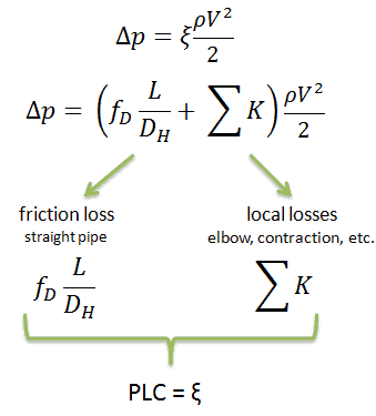
PLC - Pressure loss coefficient - equationsAs was written, natural circulation flow rate, V, in the loop, under steady state condition is determined from the balance between the driving head and the resisting forces. Like pipe friction, the overall pressure losses are proportional to the square of the flow rate and therefore they can be easily integrated into the Darcy-Weisbach equation. Engineers often use the pressure loss coefficient, PLC. It is noted K or ξ (pronounced “xi”). This coefficient characterizes pressure loss of a certain hydraulic system or of a part of a hydraulic system. It can be easily measured in hydraulic loops. The pressure loss coefficient can be defined or measured for both straight pipes and especially for local (minor) losses. Since the Darcy friction factor is a function of velocity (in Reynolds number), then the calculation of the pressure loss coefficient is an iterative process.

 
References:
Heat Transfer:
  1. Fundamentals of Heat and Mass Transfer, 7th Edition. Theodore L. Bergman, Adrienne S. Lavine, Frank P. Incropera. John Wiley & Sons, Incorporated, 2011. ISBN: 9781118137253.
  2. Heat and Mass Transfer. Yunus A. Cengel. McGraw-Hill Education, 2011. ISBN: 9780071077866.
  3. U.S. Department of Energy, Thermodynamics, Heat Transfer and Fluid Flow. DOE Fundamentals Handbook, Volume 2 of 3. May 2016.

Nuclear and Reactor Physics:

  1. J. R. Lamarsh, Introduction to Nuclear Reactor Theory, 2nd ed., Addison-Wesley, Reading, MA (1983).
  2. J. R. Lamarsh, A. J. Baratta, Introduction to Nuclear Engineering, 3d ed., Prentice-Hall, 2001, ISBN: 0-201-82498-1.
  3. W. M. Stacey, Nuclear Reactor Physics, John Wiley & Sons, 2001, ISBN: 0- 471-39127-1.
  4. Glasstone, Sesonske. Nuclear Reactor Engineering: Reactor Systems Engineering, Springer; 4th edition, 1994, ISBN: 978-0412985317
  5. W.S.C. Williams. Nuclear and Particle Physics. Clarendon Press; 1 edition, 1991, ISBN: 978-0198520467
  6. G.R.Keepin. Physics of Nuclear Kinetics. Addison-Wesley Pub. Co; 1st edition, 1965
  7. Robert Reed Burn, Introduction to Nuclear Reactor Operation, 1988.
  8. U.S. Department of Energy, Nuclear Physics and Reactor Theory. DOE Fundamentals Handbook, Volume 1 and 2. January 1993.
  9. Paul Reuss, Neutron Physics. EDP Sciences, 2008. ISBN: 978-2759800414.

Advanced Reactor Physics:

  1. K. O. Ott, W. A. Bezella, Introductory Nuclear Reactor Statics, American Nuclear Society, Revised edition (1989), 1989, ISBN: 0-894-48033-2.
  2. K. O. Ott, R. J. Neuhold, Introductory Nuclear Reactor Dynamics, American Nuclear Society, 1985, ISBN: 0-894-48029-4.
  3. D. L. Hetrick, Dynamics of Nuclear Reactors, American Nuclear Society, 1993, ISBN: 0-894-48453-2.
  4. E. E. Lewis, W. F. Miller, Computational Methods of Neutron Transport, American Nuclear Society, 1993, ISBN: 0-894-48452-4.

See also:

Natural Circulation

We hope, this article, Condition for Natural Circulation, helps you. If so, give us a like in the sidebar. Main purpose of this website is to help the public to learn some interesting and important information about thermal engineering.

What is Thermal Driving Head – Definition

Thermal driving head is the force that causes natural circulation to take place. It is caused by the difference in density between two bodies or areas of fluid. Thermal Engineering

Thermal Driving Head

Thermal driving head is the force that causes natural circulation to take place. It is caused by the difference in density between two bodies or areas of fluid. Consider two equal volumes of the same type of fluid. If the two volumes are not at the same temperature, then the volume with the higher temperature will also have a lower density and, therefore, less mass. It is known that the density of gases and liquids depends on temperature, generally decreasing (due to fluid expansion) with increasing temperature. Since the volume at the higher temperature will have a lower mass, it will also have less force exerted on it by gravity. This difference in the force of gravity exerted on the fluid will tend to cause the hotter fluid to rise and the colder fluid to sink. Thermal driving head can be simply calculated using the difference in hydrostatic pressures:

thermal driving head - equation

As can be seen, the greater the temperature difference between the hot and cold areas of fluid, the greater the thermal driving head and the resulting flow rate.

 
Density of water as a function of temperature
Chart - density - water - temperature

Density of water as a function of temperature

Natural Circulation – Flow Rate

Natural circulation flow rate in the loop, under steady state condition is determined from the balance between the driving and the resisting forces. Driving force results from density difference between hot leg and cold leg of the loop. The head required to compensate for the head losses is created by density gradients and elevation changes.

 
References:
Heat Transfer:
  1. Fundamentals of Heat and Mass Transfer, 7th Edition. Theodore L. Bergman, Adrienne S. Lavine, Frank P. Incropera. John Wiley & Sons, Incorporated, 2011. ISBN: 9781118137253.
  2. Heat and Mass Transfer. Yunus A. Cengel. McGraw-Hill Education, 2011. ISBN: 9780071077866.
  3. U.S. Department of Energy, Thermodynamics, Heat Transfer and Fluid Flow. DOE Fundamentals Handbook, Volume 2 of 3. May 2016.

Nuclear and Reactor Physics:

  1. J. R. Lamarsh, Introduction to Nuclear Reactor Theory, 2nd ed., Addison-Wesley, Reading, MA (1983).
  2. J. R. Lamarsh, A. J. Baratta, Introduction to Nuclear Engineering, 3d ed., Prentice-Hall, 2001, ISBN: 0-201-82498-1.
  3. W. M. Stacey, Nuclear Reactor Physics, John Wiley & Sons, 2001, ISBN: 0- 471-39127-1.
  4. Glasstone, Sesonske. Nuclear Reactor Engineering: Reactor Systems Engineering, Springer; 4th edition, 1994, ISBN: 978-0412985317
  5. W.S.C. Williams. Nuclear and Particle Physics. Clarendon Press; 1 edition, 1991, ISBN: 978-0198520467
  6. G.R.Keepin. Physics of Nuclear Kinetics. Addison-Wesley Pub. Co; 1st edition, 1965
  7. Robert Reed Burn, Introduction to Nuclear Reactor Operation, 1988.
  8. U.S. Department of Energy, Nuclear Physics and Reactor Theory. DOE Fundamentals Handbook, Volume 1 and 2. January 1993.
  9. Paul Reuss, Neutron Physics. EDP Sciences, 2008. ISBN: 978-2759800414.

Advanced Reactor Physics:

  1. K. O. Ott, W. A. Bezella, Introductory Nuclear Reactor Statics, American Nuclear Society, Revised edition (1989), 1989, ISBN: 0-894-48033-2.
  2. K. O. Ott, R. J. Neuhold, Introductory Nuclear Reactor Dynamics, American Nuclear Society, 1985, ISBN: 0-894-48029-4.
  3. D. L. Hetrick, Dynamics of Nuclear Reactors, American Nuclear Society, 1993, ISBN: 0-894-48453-2.
  4. E. E. Lewis, W. F. Miller, Computational Methods of Neutron Transport, American Nuclear Society, 1993, ISBN: 0-894-48452-4.

See also:

Natural Circulation

We hope, this article, Thermal Driving Head, helps you. If so, give us a like in the sidebar. Main purpose of this website is to help the public to learn some interesting and important information about thermal engineering.

What is Hydraulic Resisting Force – Definition

Hydraulic Resisting Force. Natural circulation flow rate, V, is determined from the balance between the driving head and the resisting forces. Thermal Engineering

Hydraulic Resisting Force

PLC - Pressure loss coefficient - equationsAs was written, natural circulation flow rate, V, in the loop, under steady state condition is determined from the balance between the driving head and the resisting forces. Like pipe friction, the overall pressure losses are proportional to the square of the flow rate and therefore they can be easily integrated into the Darcy-Weisbach equation. Engineers often use the pressure loss coefficient, PLC. It is noted K or ξ (pronounced “xi”). This coefficient characterizes pressure loss of a certain hydraulic system or of a part of a hydraulic system. It can be easily measured in hydraulic loops. The pressure loss coefficient can be defined or measured for both straight pipes and especially for local (minor) losses. Since the Darcy friction factor is a function of velocity (in Reynolds number), then the calculation of the pressure loss coefficient is an iterative process.

Natural Circulation – Flow Rate

Natural circulation flow rate in the loop, under steady state condition is determined from the balance between the driving and the resisting forces. Driving force results from density difference between hot leg and cold leg of the loop. The head required to compensate for the head losses is created by density gradients and elevation changes.

 
References:
Heat Transfer:
  1. Fundamentals of Heat and Mass Transfer, 7th Edition. Theodore L. Bergman, Adrienne S. Lavine, Frank P. Incropera. John Wiley & Sons, Incorporated, 2011. ISBN: 9781118137253.
  2. Heat and Mass Transfer. Yunus A. Cengel. McGraw-Hill Education, 2011. ISBN: 9780071077866.
  3. U.S. Department of Energy, Thermodynamics, Heat Transfer and Fluid Flow. DOE Fundamentals Handbook, Volume 2 of 3. May 2016.

Nuclear and Reactor Physics:

  1. J. R. Lamarsh, Introduction to Nuclear Reactor Theory, 2nd ed., Addison-Wesley, Reading, MA (1983).
  2. J. R. Lamarsh, A. J. Baratta, Introduction to Nuclear Engineering, 3d ed., Prentice-Hall, 2001, ISBN: 0-201-82498-1.
  3. W. M. Stacey, Nuclear Reactor Physics, John Wiley & Sons, 2001, ISBN: 0- 471-39127-1.
  4. Glasstone, Sesonske. Nuclear Reactor Engineering: Reactor Systems Engineering, Springer; 4th edition, 1994, ISBN: 978-0412985317
  5. W.S.C. Williams. Nuclear and Particle Physics. Clarendon Press; 1 edition, 1991, ISBN: 978-0198520467
  6. G.R.Keepin. Physics of Nuclear Kinetics. Addison-Wesley Pub. Co; 1st edition, 1965
  7. Robert Reed Burn, Introduction to Nuclear Reactor Operation, 1988.
  8. U.S. Department of Energy, Nuclear Physics and Reactor Theory. DOE Fundamentals Handbook, Volume 1 and 2. January 1993.
  9. Paul Reuss, Neutron Physics. EDP Sciences, 2008. ISBN: 978-2759800414.

Advanced Reactor Physics:

  1. K. O. Ott, W. A. Bezella, Introductory Nuclear Reactor Statics, American Nuclear Society, Revised edition (1989), 1989, ISBN: 0-894-48033-2.
  2. K. O. Ott, R. J. Neuhold, Introductory Nuclear Reactor Dynamics, American Nuclear Society, 1985, ISBN: 0-894-48029-4.
  3. D. L. Hetrick, Dynamics of Nuclear Reactors, American Nuclear Society, 1993, ISBN: 0-894-48453-2.
  4. E. E. Lewis, W. F. Miller, Computational Methods of Neutron Transport, American Nuclear Society, 1993, ISBN: 0-894-48452-4.

See also:

Natural Circulation

We hope, this article, Hydraulic Resisting Force, helps you. If so, give us a like in the sidebar. Main purpose of this website is to help the public to learn some interesting and important information about thermal engineering.

What is Natural Circulation in Reactor Engineering – Definition

In reactor engineering, natural circulation is very desired phenomenon, since it is capable to provide reactor core cooling after the loss of RCPs. Thermal Engineering

Natural Circulation in Reactor Engineering

Natural Circulation - schema
Natural circulation in a closed loop

In reactor engineering, natural circulation is very desired phenomenon, since it is capable to provide reactor core cooling after the loss of RCPs (e.g. after loss of offsite power – LOOP). In PWRs, plant design provides an elevation difference, h, of approximately 12 meters between the centerline of the steam generator and the centerline of the reactor core. The layout of the system must ensure natural circulation capability following a loss of flow to permit cooldown without overheating the core. Moreover, the interconnecting piping from the reactor pressure vessel to the steam generators must be intact, free from obstructions such as non-condensable gasses (e.g. steam pockets). In this way, natural circulation will ensure that the fluid will continue to flow as long as the reactor is hotter than the heat sink, even when power cannot be supplied to the pumps.

RCPs are not usually “safety system”, as defined. After the loss of RCPs (e.g. after loss of offsite power – LOOP) the reactor must be shutdown immediately, since RCPs slowly coast down to zero flow rate. Sufficient and safe residual heat removal is then ensured by a natural circulation flow through the reactor. With no forced flow, the coolant in the core begins to heat up. The increase in coolant temperature causes a reduction in coolant density, which in turn moves the coolant into the steam generator. It must be noted, natural circulation is not sufficient to remove the heat being generated when the reactor is at power.

Modern reactor designs use natural circulation a very important safety feature. Many passive safety systems in modern reactor designs operate without using any pumps, which creates increased design safety, integrity, and reliability, while simultaneously reducing overall reactor cost.

Indicators of Natural Circulation

In PWRs, various parameters can be used to indicate or verify natural circulation is occurring. This is dependent on plant type and plant systems. For instance for a PWR selected parameters that can be used are as follows:

  • Ideally, the flow rate can be measured in each of loops.
  • ΔT (THot – TCold). The temperature difference between hot legs and cold legs should be 25-80% of the full power value and either steady or slowly decreasing. This indicates that the decay heat is being removed from the system at an adequate rate to maintain or reduce core temperatures.
  • Hot and cold leg temperatures should be steady or slowly decreasing. Again, this indicates that heat is being removed and the decay heat load is decreasing as expected.
  • Steam generator steam pressure (secondary side pressure) should be following reactor coolant system temperature. This verifies that the steam generator is removing heat from the RCS coolant.

Special Reference: Natural circulation in water cooled nuclear power plants, IAEA-TECDOC-1474. IAEA, 2005. ISBN 92–0–110605–X.

 
References:
Heat Transfer:
  1. Fundamentals of Heat and Mass Transfer, 7th Edition. Theodore L. Bergman, Adrienne S. Lavine, Frank P. Incropera. John Wiley & Sons, Incorporated, 2011. ISBN: 9781118137253.
  2. Heat and Mass Transfer. Yunus A. Cengel. McGraw-Hill Education, 2011. ISBN: 9780071077866.
  3. U.S. Department of Energy, Thermodynamics, Heat Transfer and Fluid Flow. DOE Fundamentals Handbook, Volume 2 of 3. May 2016.

Nuclear and Reactor Physics:

  1. J. R. Lamarsh, Introduction to Nuclear Reactor Theory, 2nd ed., Addison-Wesley, Reading, MA (1983).
  2. J. R. Lamarsh, A. J. Baratta, Introduction to Nuclear Engineering, 3d ed., Prentice-Hall, 2001, ISBN: 0-201-82498-1.
  3. W. M. Stacey, Nuclear Reactor Physics, John Wiley & Sons, 2001, ISBN: 0- 471-39127-1.
  4. Glasstone, Sesonske. Nuclear Reactor Engineering: Reactor Systems Engineering, Springer; 4th edition, 1994, ISBN: 978-0412985317
  5. W.S.C. Williams. Nuclear and Particle Physics. Clarendon Press; 1 edition, 1991, ISBN: 978-0198520467
  6. G.R.Keepin. Physics of Nuclear Kinetics. Addison-Wesley Pub. Co; 1st edition, 1965
  7. Robert Reed Burn, Introduction to Nuclear Reactor Operation, 1988.
  8. U.S. Department of Energy, Nuclear Physics and Reactor Theory. DOE Fundamentals Handbook, Volume 1 and 2. January 1993.
  9. Paul Reuss, Neutron Physics. EDP Sciences, 2008. ISBN: 978-2759800414.

Advanced Reactor Physics:

  1. K. O. Ott, W. A. Bezella, Introductory Nuclear Reactor Statics, American Nuclear Society, Revised edition (1989), 1989, ISBN: 0-894-48033-2.
  2. K. O. Ott, R. J. Neuhold, Introductory Nuclear Reactor Dynamics, American Nuclear Society, 1985, ISBN: 0-894-48029-4.
  3. D. L. Hetrick, Dynamics of Nuclear Reactors, American Nuclear Society, 1993, ISBN: 0-894-48453-2.
  4. E. E. Lewis, W. F. Miller, Computational Methods of Neutron Transport, American Nuclear Society, 1993, ISBN: 0-894-48452-4.

See also:

Natural Circulation

We hope, this article, Natural Circulation in Reactor Engineering, helps you. If so, give us a like in the sidebar. Main purpose of this website is to help the public to learn some interesting and important information about thermal engineering.

What is Boiling and Condensation – Definition

Boiling and condensation differ from other forms of convection in that they depend on the latent heat of vaporization, which is very high. Boiling and Condensation

Boiling and Condensation

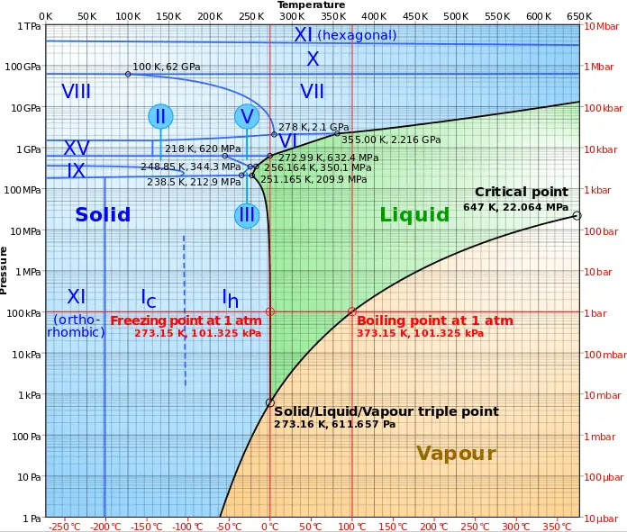
Phase diagram of water
Phase diagram of water.
Source: wikipedia.org CC BY-SA

In preceding chapters, we have discussed convective heat transfer with very important assumption. We have assumed a single-phase convective heat transfer without any phase change. In this chapter we focus on convective heat transfer associated with the change in phase of a fluid. In particular, we consider processes that can occur at a solid–liquid or solid–vapor interface, namely, boiling (liquid-to-vapor phase change) and condensation (vapor-to-liquid phase change).

For these cases latent heat effects associated with the phase change are significant. Latent heat, known also as the enthalpy of vaporization, is the amount of heat added to or removed from a substance to produce a change in phase. This energy breaks down the intermolecular attractive forces, and also must provide the energy necessary to expand the gas (the pΔV work). When latent heat is added, no temperature change occurs.

Latent heat of vaporization - water at 0.1 MPa, 3 MPa, 16 MPa
The heat of vaporization diminishes with increasing pressure, while the boiling point increases. It vanishes completely at a certain point called the critical point.

The enthalpy of vaporization is a function of the pressure at which that transformation takes place.

Latent heat of vaporization – water at 0.1 MPa (atmospheric pressure)

hlg = 2257 kJ/kg

Latent heat of vaporization – water at 3 MPa (pressure inside a steam generator)

hlg = 1795 kJ/kg

Latent heat of vaporization – water at 16 MPa (pressure inside a pressurizer)

hlg = 931 kJ/kg

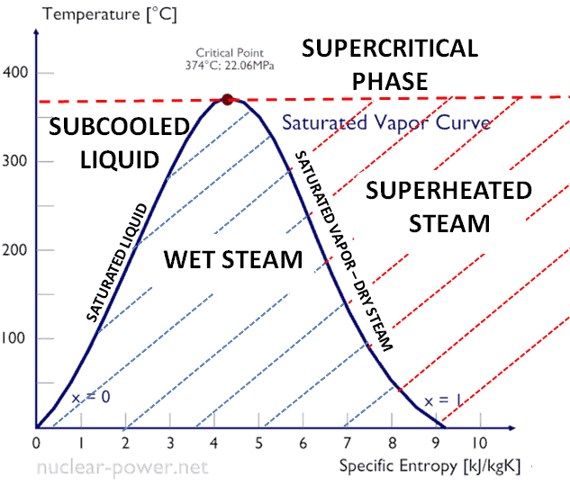
supercritical-phase-critical-point-minThe heat of vaporization diminishes with increasing pressure, while the boiling point increases. It vanishes completely at a certain point called the critical point. Above the critical point, the liquid and vapor phases are indistinguishable, and the substance is called a supercritical fluid.

The change from the liquid to the vapor state due to boiling is sustained by heat transfer from the solid surface; conversely, condensation of a vapor to the liquid state results in heat transfer to the solid surface. Boiling and condensation differ from other forms of convection in that they depend on the latent heat of vaporization, which is very high for common pressures, therefore large amounts of heat can be transferred during boiling and condensation essentially at constant temperature. Heat transfer coefficients, h, associated with boiling and condensation are typically much higher than those encountered in other forms of convection processes that involve a single phase.

This is due to the fact, even in turbulent flow, there is a stagnant fluid film layer (laminar sublayer), that isolates the surface of the heat exchanger. This stagnant fluid film layer plays crucial role for the convective heat transfer coefficient. It is observed, that the fluid comes to a complete stop at the surface and assumes a zero velocity relative to the surface. This phenomenon is known as the no-slip condition and therefore, at the surface, energy flow occurs purely by conduction. But in the next layers both conduction and diffusion-mass movement in the molecular level or macroscopic level occurs. Due to the mass movement the rate of energy transfer is higher. As was written, nucleate boiling at the surface effectively disrupts this stagnant layer and therefore nucleate boiling significantly increases the ability of a surface to transfer thermal energy to bulk fluid.

 
Two-phase Fluid Flow
two-phase fluid flowBy definition, multiphase flow is the interactive flow of two or more distinct phases with common interfaces in, say, a conduit. Each phase, representing a volume fraction (or mass fraction) of solid, liquid or gaseous matter, has its own properties, velocity, and temperature.

A multiphase flow can be simultaneous flow of:

  • Materials with different states or phases (e.g. water-steam mixture).
  • Materials with different chemical properties but in the same state or phase (e.g. oil droplets in water).

There are many combinations in industrial processes, but the most common being the simultaneous flow of steam and liquid water (as encountered in steam generators and condensers). In reactor engineering a great deal of study has been performed on the nature of two-phase flow in case of a loss-of-coolant accident (LOCA), which is an accident of importance in reactor safety and in all thermal-hydraulic analyses (DNBR analyses).

Characteristics of Two-phase Fluid Flow

All two-phase flow problems have features which are characteristically different from those found in single-phase problems.

  • In the case of steam and liquid water the density of the two phases differs by a factor of about 1000. Therefore the influence of gravitational body force on multiphase flows is of much greater importance than in the case of single-phase flows.
  • The sound speed changes dramatically for materials undergoing phase change, and can be orders of magnitude different. This significantly influences a flow through an orifice.
  • The relative concentration of different phases is usually a dependent parameter of great importance in multiphase flows, while it is a parameter of no consequence in single-phase flows.
  • The change of phase means flow-induced pressure drops can cause further phase-change (e.g. water can evaporate through an orifice) increasing the relative volume of the gaseous, compressible medium and increasing efflux velocities, unlike single-phase incompressible flow where decreasing of an orifice would decrease efflux velocities.
  • The spatial distribution of the various phases in the flow channel strongly affects the flow behavior.
  • There are many types of instabilities in multiphase flow.

Boiling Point – Saturation

In thermodynamics, the term saturation defines a condition in which a mixture of vapor and liquid can exist together at a given temperature and pressure. The temperature at which vaporization (boiling) starts to occur for a given pressure is called the saturation temperature or boiling point. The pressure at which vaporization (boiling) starts to occur for a given temperature is called the saturation pressure.

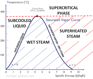
When the vapor quality is equal to 0, it is referred to as the saturated liquid state (single-phase). On the other hand, when the vapor quality is equal to 1, it is referred to as the saturated vapor state or dry steam (single-phase). Between these two states, we talk about vapor-liquid mixture or wet steam (two-phase mixture). At constant pressure, an addition of energy does not changes the temperature of the mixture, but the vapor quality and specific volume changes.

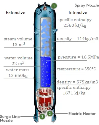
Saturation in Pressurizer

Extensive vs. intensive thermodynamic properties
Extensive and intensive properties of medium in the pressurizer.

A pressurizer is a component of a pressurized water reactor. Pressure in the primary circuit of PWRs is maintained by a pressurizer, a separate vessel that is connected to the primary circuit (hot leg) and partially filled with water which is heated to the saturation temperature (boiling point) for the desired pressure by submerged electrical heaters. Temperature in the pressurizer can be maintained at 350 °C (662 °F), which gives a subcooling margin (the difference between the pressurizer temperature and the highest temperature in the reactor core) of 30 °C. Subcooling margin is very important safety parameter of PWRs, since the boiling in the reactor core must be excluded. The basic design of the pressurized water reactor includes such requirement that the coolant (water) in the reactor coolant system must not boil. To achieve this, the coolant in the reactor coolant system is maintained at a pressure sufficiently high that boiling does not occur at the coolant temperatures experienced while the plant is operating or in an analyzed transient.

Functions

Pressure in the pressurizer is controlled by varying the temperature of the coolant in the pressurizer. For these purposes two systems are installed. Water spray system and electrical heaters system. Volume of the pressurizer (tens of cubic meters) is filled with water on saturation parameters and steam. The water spray system (relatively cool water – from cold leg) can decrease the pressure in the vessel by condensing the steam on water droplets sprayed in the vessel. On the other hand the submerged electrical heaters are designed to increase the pressure by evaporation the water in the vessel. Water pressure in a closed system tracks water temperature directly; as the temperature goes up, pressure goes up.

Boiling in Steam Generator

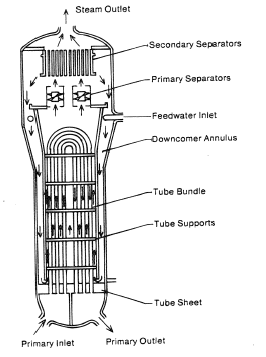
Steam Generator - vertical
Steam Generator – vertical

Steam generators are heat exchangers used to convert feedwater into steam from heat produced in a nuclear reactor core. The steam produced drives the turbine. They are used in the most nuclear power plants, but there are many types according to the reactor type.

The hot primary coolant (water 330°C; 626°F; 16MPa) is pumped into the steam generator through primary inlet. High pressure of primary coolant is used to keep the water in the liquid state. Boiling of the primary coolant shall not occur. The liquid water flows through hundreds or thousands of tubes (usually 1.9 cm in diameter) inside the steam generator. The feedwater (secondary circuit) is heated from ~260°C 500°F to the boiling point of that fluid (280°C; 536°F; 6,5MPa). Heat is transferred through the walls of these tubes to the lower pressure secondary coolant located on the secondary side of the exchanger where the coolant evaporates to pressurized steam (saturated steam 280°C; 536°F; 6,5 MPa). The pressurized steam leaves the steam generator through a steam outlet and continues to the steam turbine. The transfer of heat is accomplished without mixing the two fluids to prevent the secondary coolant from becoming radioactive. The primary coolant leaves (water 295°C; 563°F; 16MPa) the steam generator through primary outlet and continues through a cold leg to a reactor coolant pump and then into the reactor.

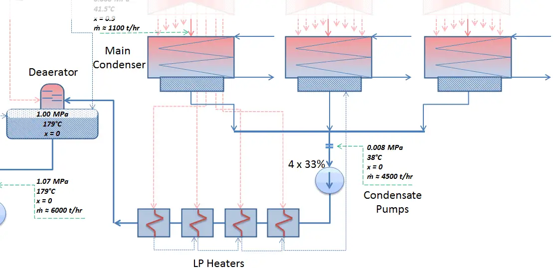
Condensation in Main Condenser

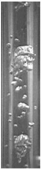
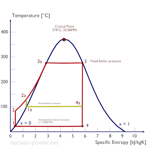
Condenser - LP Heaters - DeaeratorThe condenser must maintain a sufficient low vacuum in order to increase the power plant efficiency. The vacuum pumps maintain a sufficient vacuum in the condenser by extracting air and uncondensed gases. The lowest feasible condenser pressure is the saturation pressure corresponding to the ambient temperature (e.g. absolute pressure of 0.008 MPa, which corresponds to 41.5°C). Note that, there is always a temperature difference between (around ΔT = 14°C) the condenser temperature and the ambient temperature, which originates from finite size and efficiency of condensers. Since neither the condenser is 100% efficient heat exchanger, there is always a temperature difference between the saturation temperature (secondary side) and the temperature of the coolant in the cooling system. Moreover, there is a design inefficiciency, which decreases the overall efficiency of the turbine. Ideally the steam exhausted into the condenser would have no subcooling. But real condensers are designed to subcool the liquid by a few degrees of Celsius in order to avoid the suction cavitation in the condensate pumps. But, this subcooling increases the inefficiency of the cycle, because more energy is needed to reheat the water.

Rankine Cycle - condenser pressure
Decreasing the turbine exhaust pressure increases the net work per cycle but also decreses the vapor quality of outlet steam.

The goal of maintaining the lowest practical turbine exhaust pressure is a primary reason for including the condenser in a thermal power plant. The condenser provides a vacuum that maximizes the energy extracted from the steam, resulting in a significant increase in net work and thermal efficiency. But also this parameter (condenser pressure) has its engineering limits:

  • Decreasing the turbine exhaust pressure decreases the vapor quality (or dryness fraction). At some point the expansion must be ended to avoid damages that could be caused to blades of steam turbine by low quality steam.
  • Decreasing the turbine exhaust pressure significantly increases the specific volume of exhausted steam, which requires huge blades in last rows of low-pressure stage of the steam turbine.

In a typical wet steam turbine, the exhausted steam condenses in the condenser and it is at a pressure well below atmospheric (absolute pressure of 0.008 MPa, which corresponds to 41.5°C). This steam is in a partially condensed state (point F), typically of a quality near 90%. Note that, the pressure inside the condenser is also dependent on the ambient atmospheric conditions:

  • air temperature, pressure and humidity in case of cooling into the atmosphere
  • water temperature and the flow rate in case of cooling into a river or sea

steam properties - steam tablesAn increase in the ambient temperature causes a proportional increase in pressure of exhausted steam (ΔT = 14°C is usually a constant) hence the thermal efficiency of the power conversion system decreases. In other words, the electrical output of a power plant may vary with ambient conditions, while the thermal power remains constant.

To maintain the parameters inside the condenser (0.008 MPa and 41.5 °C), the cooling water from cooling system must be sufficiently cold and there cannot be large temperature difference between the outlet and inlet water temperauter, hence the flowrate through the cooling system must be very high. The flowrate through the cooling system (with wet cooling towers) may be up to 100 000 m3/h (27.7 m3/s). The condenser inlet water may have about 22°C (strongly depending on ambient conditions), while the condenser outlet may have about 25°C. The sea water cooling systems operate at higher flowrates, for example, 130 000 m3/h.

 
References:
Heat Transfer:
  1. Fundamentals of Heat and Mass Transfer, 7th Edition. Theodore L. Bergman, Adrienne S. Lavine, Frank P. Incropera. John Wiley & Sons, Incorporated, 2011. ISBN: 9781118137253.
  2. Heat and Mass Transfer. Yunus A. Cengel. McGraw-Hill Education, 2011. ISBN: 9780071077866.
  3. U.S. Department of Energy, Thermodynamics, Heat Transfer and Fluid Flow. DOE Fundamentals Handbook, Volume 2 of 3. May 2016.

Nuclear and Reactor Physics:

  1. J. R. Lamarsh, Introduction to Nuclear Reactor Theory, 2nd ed., Addison-Wesley, Reading, MA (1983).
  2. J. R. Lamarsh, A. J. Baratta, Introduction to Nuclear Engineering, 3d ed., Prentice-Hall, 2001, ISBN: 0-201-82498-1.
  3. W. M. Stacey, Nuclear Reactor Physics, John Wiley & Sons, 2001, ISBN: 0- 471-39127-1.
  4. Glasstone, Sesonske. Nuclear Reactor Engineering: Reactor Systems Engineering, Springer; 4th edition, 1994, ISBN: 978-0412985317
  5. W.S.C. Williams. Nuclear and Particle Physics. Clarendon Press; 1 edition, 1991, ISBN: 978-0198520467
  6. G.R.Keepin. Physics of Nuclear Kinetics. Addison-Wesley Pub. Co; 1st edition, 1965
  7. Robert Reed Burn, Introduction to Nuclear Reactor Operation, 1988.
  8. U.S. Department of Energy, Nuclear Physics and Reactor Theory. DOE Fundamentals Handbook, Volume 1 and 2. January 1993.
  9. Paul Reuss, Neutron Physics. EDP Sciences, 2008. ISBN: 978-2759800414.

Advanced Reactor Physics:

  1. K. O. Ott, W. A. Bezella, Introductory Nuclear Reactor Statics, American Nuclear Society, Revised edition (1989), 1989, ISBN: 0-894-48033-2.
  2. K. O. Ott, R. J. Neuhold, Introductory Nuclear Reactor Dynamics, American Nuclear Society, 1985, ISBN: 0-894-48029-4.
  3. D. L. Hetrick, Dynamics of Nuclear Reactors, American Nuclear Society, 1993, ISBN: 0-894-48453-2.
  4. E. E. Lewis, W. F. Miller, Computational Methods of Neutron Transport, American Nuclear Society, 1993, ISBN: 0-894-48452-4.

See also:

Heat Transfer

We hope, this article, Boiling and Condensation, helps you. If so, give us a like in the sidebar. Main purpose of this website is to help the public to learn some interesting and important information about thermal engineering.
What is Boiling – Boiling Characteristics – Definition

Boiling is the phase change from the liquid to the vapor state and it occurs when a liquid is heated to its boiling point. Boiling – Boiling Characteristics

Boiling

Phase diagram of water
Phase diagram of water.
Source: wikipedia.org CC BY-SA

In preceding chapters, we have discussed convective heat transfer with very important assumption. We have assumed a single-phase convective heat transfer without any phase change. In this chapter we focus on convective heat transfer associated with the change in phase of a fluid. In particular, we consider processes that can occur at a solid–liquid or solid–vapor interface, namely, boiling (liquid-to-vapor phase change) and condensation (vapor-to-liquid phase change).

For these cases latent heat effects associated with the phase change are significant. Latent heat, known also as the enthalpy of vaporization, is the amount of heat added to or removed from a substance to produce a change in phase. This energy breaks down the intermolecular attractive forces, and also must provide the energy necessary to expand the gas (the pΔV work). When latent heat is added, no temperature change occurs.

Latent heat of vaporization - water at 0.1 MPa, 3 MPa, 16 MPa
The heat of vaporization diminishes with increasing pressure, while the boiling point increases. It vanishes completely at a certain point called the critical point.

The enthalpy of vaporization is a function of the pressure at which that transformation takes place.

Latent heat of vaporization – water at 0.1 MPa (atmospheric pressure)

hlg = 2257 kJ/kg

Latent heat of vaporization – water at 3 MPa

hlg = 1795 kJ/kg

Latent heat of vaporization – water at 16 MPa (pressure inside a pressurizer)

hlg = 931 kJ/kg

The heat of vaporization diminishes with increasing pressure, while the boiling point increases. It vanishes completely at a certain point called the critical point. Above the critical point, the liquid and vapor phases are indistinguishable, and the substance is called a supercritical fluid.

supercritical-phase-critical-point-minThe change from the liquid to the vapor state due to boiling is sustained by heat transfer from the solid surface; conversely, condensation of a vapor to the liquid state results in heat transfer to the solid surface. Boiling and condensation differ from other forms of convection in that they depend on the latent heat of vaporization, which is very high for common pressures, therefore large amounts of heat can be transferred during boiling and condensation essentially at constant temperature. Heat transfer coefficients, h, associated with boiling and condensation are typically much higher than those encountered in other forms of convection processes that involve a single phase.

This is due to the fact, even in turbulent flow, there is a stagnant fluid film layer (laminar sublayer), that isolates the surface of the heat exchanger. This stagnant fluid film layer plays crucial role for the convective heat transfer coefficient. It is observed, that the fluid comes to a complete stop at the surface and assumes a zero velocity relative to the surface. This phenomenon is known as the no-slip condition and therefore, at the surface, energy flow occurs purely by conduction. But in the next layers both conduction and diffusion-mass movement in the molecular level or macroscopic level occurs. Due to the mass movement the rate of energy transfer is higher. As was written, nucleate boiling at the surface effectively disrupts this stagnant layer and therefore nucleate boiling significantly increases the ability of a surface to transfer thermal energy to bulk fluid.

 
Two-phase Fluid Flow
two-phase fluid flowBy definition, multiphase flow is the interactive flow of two or more distinct phases with common interfaces in, say, a conduit. Each phase, representing a volume fraction (or mass fraction) of solid, liquid or gaseous matter, has its own properties, velocity, and temperature.

A multiphase flow can be simultaneous flow of:

  • Materials with different states or phases (e.g. water-steam mixture).
  • Materials with different chemical properties but in the same state or phase (e.g. oil droplets in water).

There are many combinations in industrial processes, but the most common being the simultaneous flow of steam and liquid water (as encountered in steam generators and condensers). In reactor engineering a great deal of study has been performed on the nature of two-phase flow in case of a loss-of-coolant accident (LOCA), which is an accident of importance in reactor safety and in all thermal-hydraulic analyses (DNBR analyses).

Characteristics of Two-phase Fluid Flow

All two-phase flow problems have features which are characteristically different from those found in single-phase problems.

  • In the case of steam and liquid water the density of the two phases differs by a factor of about 1000. Therefore the influence of gravitational body force on multiphase flows is of much greater importance than in the case of single-phase flows.
  • The sound speed changes dramatically for materials undergoing phase change, and can be orders of magnitude different. This significantly influences a flow through an orifice.
  • The relative concentration of different phases is usually a dependent parameter of great importance in multiphase flows, while it is a parameter of no consequence in single-phase flows.
  • The change of phase means flow-induced pressure drops can cause further phase-change (e.g. water can evaporate through an orifice) increasing the relative volume of the gaseous, compressible medium and increasing efflux velocities, unlike single-phase incompressible flow where decreasing of an orifice would decrease efflux velocities.
  • The spatial distribution of the various phases in the flow channel strongly affects the flow behavior.
  • There are many types of instabilities in multiphase flow.
Boiling Point - Saturation
In thermodynamics, the term saturation defines a condition in which a mixture of vapor and liquid can exist together at a given temperature and pressure. The temperature at which vaporization (boiling) starts to occur for a given pressure is called the saturation temperature or boiling point. The pressure at which vaporization (boiling) starts to occur for a given temperature is called the saturation pressure.

When the vapor quality is equal to 0, it is referred to as the saturated liquid state (single-phase). On the other hand, when the vapor quality is equal to 1, it is referred to as the saturated vapor state or dry steam (single-phase). Between these two states, we talk about vapor-liquid mixture or wet steam (two-phase mixture). At constant pressure, an addition of energy does not changes the temperature of the mixture, but the vapor quality and specific volume changes.

Boiling Modes – Types of Boiling

Pool Boiling - Boiling ModesFrom a practical engineering point of view boiling can be categorized according to several criteria.

Categorization by the flow regime:

  • Pool Boiling. Perhaps the most common configuration, known as pool boiling is when a pool of liquid is heated from below through a horizontal surface. In pool boiling the liquid is quiescent and its motion near the surface is primarily due to natural convection and to mixing induced by bubble growth and detachment. The pioneering work on pool boiling was done in 1934 by S. Nukiyama. He was the first to identify four well known different regimes of pool boiling using his apparatus.
  • Flow Boiling - Boiling ModesFlow Boiling. In flow boiling (or forced convection boiling), fluid flow is forced over a surface by external means such as a pump, as well as by buoyancy effects.  Therefore, flow boiling is always accompanied by other convection effects. Conditions depend strongly on geometry, which may involve external flow over heated plates and cylinders or internal (duct) flow. In nuclear reactors, most of boiling regimes are just forced convection boiling.

Categorization by the wall superheat temperature, ΔTsat:

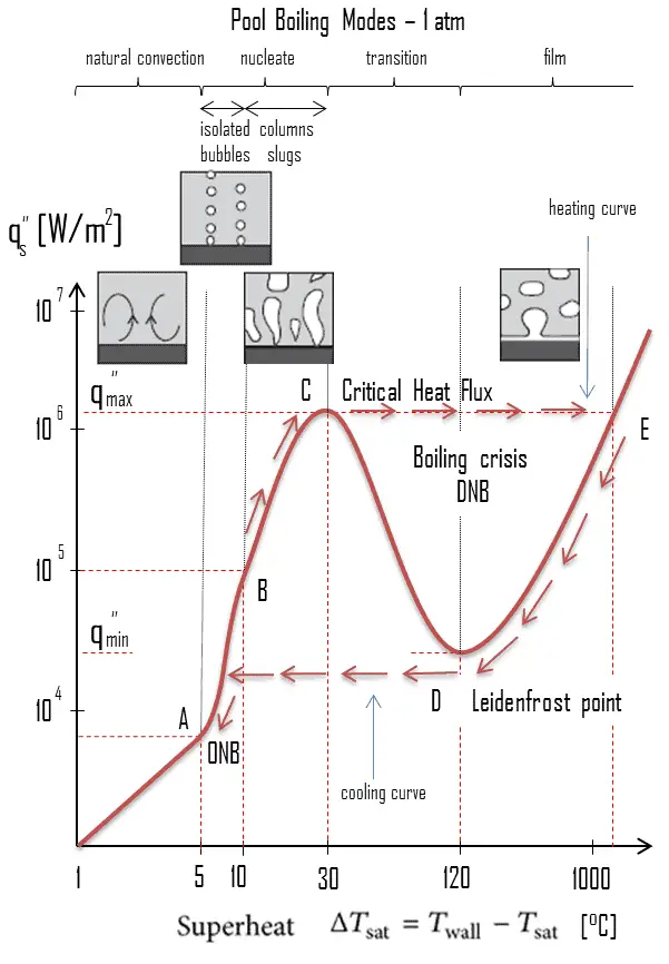
Boiling Curve - Boiling ModesThe pioneering work on boiling was done in 1934 by S. Nukiyama, who used electrically heated nichrome and platinum wires immersed in liquids in his experiments. Nukiyama was the first to identify different regimes of pool boiling using his apparatus. He noticed that boiling takes different forms, depending on the value of the wall superheat temperature ΔTsat (known also as the excess temperature), which is defined as the difference between the wall temperature, Twall and the saturation temperature, Tsat.

Four different boiling regimes  of pool boiling (based on the excess temperature) are observed:

  • Natural Convection Boiling                            ΔTsat < 5°C
  • Nucleate Boiling                                   5°C < ΔTsat < 30°C
  • Transition Boiling                                 30°C < ΔTsat < 200°C
  • Film Boiling                                        200°C < ΔTsat

Description of Boiling Modes:

  • Natural Convection BoilingNatural Convection Boiling. In thermodynamics, the requirement for boiling of pure substances to occur is that Twall = Tsat. But in real experiments, boiling does not occur until the liquid is heated a few degrees above the saturation temperature. The surface temperature must be somewhat above the saturation temperature in order to sustain vapor formation. In this boiling mode, vapour will be observed over the water surface, but usually no bubbles will be observed. As the superheat temperature is increased, bubble inception will eventually occur, but below point A, fluid motion is determined principally by natural convection currents. The point A is usually referred to as the onset of nucleate boiling – ONB.
  • Nucleate Boiling - Boiling ModesNucleate Boiling. The most common type of local boiling encountered in nuclear facilities is nucleate boiling. In nucleate boiling, steam bubbles form at the heat transfer surface and then break away and are carried into the main stream of the fluid. Such movement enhances heat transfer because the heat generated at the surface is carried directly into the fluid stream. Once in the main fluid stream, the bubbles collapse because the bulk temperature of the fluid is not as high as the heat transfer surface temperature where the bubbles were created. This heat transfer process is sometimes desirable because the energy created at the heat transfer surface is quickly and efficiently “carried” away.
  • Transition Boiling - Partial Film BoilingTransition Boiling. The nucleate boiling heat flux cannot be increased indefinitely. At some value, we call it the “critical heat flux” (CHF), the steam produced can form an insulating layer over the surface, which in turn deteriorates the heat transfer coefficient. This is because a large fraction of the surface is covered by a vapor film, which acts as an thermal insulation due to the low thermal conductivity of the vapor relative to that of the liquid. Immediately after the critical heat flux has been reached, boiling become unstable and transition boiling occurs. The transition from nucleate boiling to film boiling is known as the “boiling crisis”. Since beyond the CHF point the heat transfer coefficient decreases, the transition to film boiling is usually inevitable.
  • Film Boiling - Boiling ModesFilm Boiling. A further increase in the heat flux causes a film of vapour to cover the surface. This significantly reduces the convection coefficient, since the vapor layer has significantly lower heat transfer ability. As a result the excess temperature shoots up to a very high value. Beyond the Leidenfrost point, a continuous vapor film blankets the surface and there is no contact between the liquid phase and the surface. In this situation the heat transfer is both by radiation and by conduction to the vapour. If the material is not strong enough for withstanding this temperature, the equipment will fail by damage to the material. This phenomenon is also known as burn out. In pressurized water reactors, one of key safety requirements (maybe the most important) is that a departure from nucleate boiling (DNB)  will not occur during steady state operation, normal operational transients, and anticipated operational occurrences (AOOs).  Fuel cladding integrity will be maintained if the minimum DNBR remains above the 95/95 DNBR limit for PWRs ( a 95% probability at a 95% confidence level). Since this phenomenon deteriorates the heat transfer coefficient and the heat flux remains, heat then accumulates in the fuel rod causing dramatic rise of cladding and fuel temperature. Simply, a very high temperature difference is required to transfer the critical heat flux being produced from the surface of the fuel rod to the reactor coolant (through vapor layer).

Subcooled Boiling - Boiling ModesCategorization by the subcooling temperature, ΔTsub.

Boiling may also be classified according to whether it is subcooled or saturated:

  • Subcooled boiling. In subcooled boiling, the temperature of most of the liquid is below the saturation temperature and bubbles formed at the surface may condense in the liquid. This condensation (collapsing) produces a sound of frequency ~ 100Hz – 1 KHz. This is why an electric kettle makes the most noise before the water comes to saturated boiling. The term subcooling refers to a liquid existing at a temperature below its normal boiling point.
  • Saturated Boiling. In saturated boiling (known also as bulk boiling), the temperature of the liquid slightly exceeds the saturation temperature. Bulk boiling may occur, when system temperature increases or system pressure drops to boiling point. At this point, the bubbles entering the coolant channel will not collapse. The bubbles will tend to join together and form bigger steam bubbles. Steam bubbles are then propelled through the liquid by buoyancy forces, eventually escaping from a free surface.

Saturated Boiling

 
Vapor Quality
dry-steam-saturated-vapor-minAs can be seen from the phase diagram of water, in the two-phase regions (e.g. on the border of vapor/liquid phases), specifying temperature alone will set the pressure and specifying pressure will set the temperature. But these parameters will not define the volume and enthalpy because we will need to know the relative proportion of the two phases present.

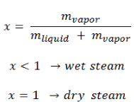
The mass fraction of the vapor in a two-phase liquid-vapor region is called the vapor quality (or dryness fraction), x, and it is given by following formula:

vapor quality

The value of the quality ranges from zero to unity. Although defined as a ratio, the quality is frequently given as a percentage. From this point of view, we distinguish between three basic types of  steam. It must be added, at x=0, we are talking about saturated liquid state (single-phase).

This classification of steam has its limitation. Consider the behavior of the system which is heated at the pressure, that is higher than the critical pressure. In this case, there would be no change in phase from liquid to steam. At all states there would be only one phase. Vaporization and condensation can occur only when the pressure is less than the critical pressure. The terms liquid and vapor tend to lose their significance.

See also: Saturation

See also: Throttling of Steam

Boiling in Nuclear Reactors

Boiling in BWRs

In BWRs boiling of coolant occurs at normal operation and it is very desired phenomenon. Typical flow qualities in BWR cores are on the order of 10 to 20 %. A boiling water reactor is cooled and moderated by water like a PWR, but at a lower pressure (7MPa), which allows the water to boil inside the pressure vessel producing the steam that runs the turbines. Evaporation therefore occurs directly in fuel channels. Therefore BWRs are the best example for this area, because evaporation of coolant occurs at normal operation and it is very desired phenomenon.

In BWRs there is a phenomenon, that is of the highest importance in reactor safety. This phenomenon is known as the “dryout” and it is directly associated with changes in flow pattern during evaporation in the high-quality region. At normal the fuel surface is effectively cooled by boiling coolant. However when the heat flux exceeds a critical value (CHF – critical heat flux) the flow pattern may reach the dryout conditions (thin film of liquid disappears). The heat transfer from the fuel surface into the coolant is deteriorated, with the result of a drastically increased fuel surface temperature.

Boiling in PWRs

Although the earliest core designs assumed that surface boiling could not be allowed in PWRs, this assumption was soon rejected and two-phase heat transfer is now one of normal operation heat transfer mechanisms also in PWRs. For PWRs at normal operation, there is a compressed liquid water inside the reactor core, loops and steam generators.  The pressure is maintained at approximately 16MPa. At this pressure water boils at approximately 350°C(662°F). As was calculated in example, the surface temperature TZr,1 = 325°C ensures, that even subcooled boiling does not occur. Note that, subcooled boiling requires TZr,1 = Tsat. Since the inlet temperatures of the water are usually about 290°C (554°F), it is obvious this example corresponds to the lower part of the core. At higher elevations of the core the bulk temperature may reach up to 330°C. The temperature difference of 29°C causes the subcooled boiling may occur (330°C + 29°C > 350°C). On the other hand, nucleate boiling at the surface effectively disrupts the stagnant layer and therefore nucleate boiling significantly increases the ability of a surface to transfer thermal energy to bulk fluid. As a result, the convective heat transfer coefficient significantly increases and therefore at higher elevations, the temperature difference (TZr,1 – Tbulk) significantly decreases.

In case of PWRs, the critical safety issue is named DNB (departure from nucleate boiling), which causes the formation of a local vapor layer, causing a dramatic reduction in heat transfer capability. This phenomenon occurs in the subcooled or low-quality region. The behaviour of the boiling crisis depends on many flow conditions (pressure, temperature, flow rate), but the boiling crisis occurs at a relatively high heat fluxes and appears to be associated with the cloud of bubbles, adjacent to the surface. These bubbles or film of vapor reduces the amount of incoming water. Since this phenomenon deteriorates the heat transfer coefficient and the heat flux remains, heat then accumulates in the fuel rod causing dramatic rise of cladding and fuel temperature.

Saturation in Pressurizer

Extensive vs. intensive thermodynamic properties
Extensive and intensive properties of medium in the pressurizer.

A pressurizer is a component of a pressurized water reactor. Pressure in the primary circuit of PWRs is maintained by a pressurizer, a separate vessel that is connected to the primary circuit (hot leg) and partially filled with water which is heated to the saturation temperature (boiling point) for the desired pressure by submerged electrical heaters. Temperature in the pressurizer can be maintained at 350 °C (662 °F), which gives a subcooling margin (the difference between the pressurizer temperature and the highest temperature in the reactor core) of 30 °C. Subcooling margin is very important safety parameter of PWRs, since the boiling in the reactor core must be excluded. The basic design of the pressurized water reactor includes such requirement that the coolant (water) in the reactor coolant system must not boil. To achieve this, the coolant in the reactor coolant system is maintained at a pressure sufficiently high that boiling does not occur at the coolant temperatures experienced while the plant is operating or in an analyzed transient.

Functions

Pressure in the pressurizer is controlled by varying the temperature of the coolant in the pressurizer. For these purposes two systems are installed. Water spray system and electrical heaters system. Volume of the pressurizer (tens of cubic meters) is filled with water on saturation parameters and steam. The water spray system (relatively cool water – from cold leg) can decrease the pressure in the vessel by condensing the steam on water droplets sprayed in the vessel. On the other hand the submerged electrical heaters are designed to increase the pressure by evaporation the water in the vessel. Water pressure in a closed system tracks water temperature directly; as the temperature goes up, pressure goes up.

Boiling in Steam Generator

Steam Generator - vertical
Steam Generator – vertical

Steam generators are heat exchangers used to convert feedwater into steam from heat produced in a nuclear reactor core. The steam produced drives the turbine. They are used in the most nuclear power plants, but there are many types according to the reactor type.

The hot primary coolant (water 330°C; 626°F; 16MPa) is pumped into the steam generator through primary inlet. High pressure of primary coolant is used to keep the water in the liquid state. Boiling of the primary coolant shall not occur. The liquid water flows through hundreds or thousands of tubes (usually 1.9 cm in diameter) inside the steam generator. The feedwater (secondary circuit) is heated from ~260°C 500°F to the boiling point of that fluid (280°C; 536°F; 6,5MPa). Heat is transferred through the walls of these tubes to the lower pressure secondary coolant located on the secondary side of the exchanger where the coolant evaporates to pressurized steam (saturated steam 280°C; 536°F; 6,5 MPa). The pressurized steam leaves the steam generator through a steam outlet and continues to the steam turbine. The transfer of heat is accomplished without mixing the two fluids to prevent the secondary coolant from becoming radioactive. The primary coolant leaves (water 295°C; 563°F; 16MPa) the steam generator through primary outlet and continues through a cold leg to a reactor coolant pump and then into the reactor.

 
References:
Heat Transfer:
  1. Fundamentals of Heat and Mass Transfer, 7th Edition. Theodore L. Bergman, Adrienne S. Lavine, Frank P. Incropera. John Wiley & Sons, Incorporated, 2011. ISBN: 9781118137253.
  2. Heat and Mass Transfer. Yunus A. Cengel. McGraw-Hill Education, 2011. ISBN: 9780071077866.
  3. U.S. Department of Energy, Thermodynamics, Heat Transfer and Fluid Flow. DOE Fundamentals Handbook, Volume 2 of 3. May 2016.

Nuclear and Reactor Physics:

  1. J. R. Lamarsh, Introduction to Nuclear Reactor Theory, 2nd ed., Addison-Wesley, Reading, MA (1983).
  2. J. R. Lamarsh, A. J. Baratta, Introduction to Nuclear Engineering, 3d ed., Prentice-Hall, 2001, ISBN: 0-201-82498-1.
  3. W. M. Stacey, Nuclear Reactor Physics, John Wiley & Sons, 2001, ISBN: 0- 471-39127-1.
  4. Glasstone, Sesonske. Nuclear Reactor Engineering: Reactor Systems Engineering, Springer; 4th edition, 1994, ISBN: 978-0412985317
  5. W.S.C. Williams. Nuclear and Particle Physics. Clarendon Press; 1 edition, 1991, ISBN: 978-0198520467
  6. G.R.Keepin. Physics of Nuclear Kinetics. Addison-Wesley Pub. Co; 1st edition, 1965
  7. Robert Reed Burn, Introduction to Nuclear Reactor Operation, 1988.
  8. U.S. Department of Energy, Nuclear Physics and Reactor Theory. DOE Fundamentals Handbook, Volume 1 and 2. January 1993.
  9. Paul Reuss, Neutron Physics. EDP Sciences, 2008. ISBN: 978-2759800414.

Advanced Reactor Physics:

  1. K. O. Ott, W. A. Bezella, Introductory Nuclear Reactor Statics, American Nuclear Society, Revised edition (1989), 1989, ISBN: 0-894-48033-2.
  2. K. O. Ott, R. J. Neuhold, Introductory Nuclear Reactor Dynamics, American Nuclear Society, 1985, ISBN: 0-894-48029-4.
  3. D. L. Hetrick, Dynamics of Nuclear Reactors, American Nuclear Society, 1993, ISBN: 0-894-48453-2.
  4. E. E. Lewis, W. F. Miller, Computational Methods of Neutron Transport, American Nuclear Society, 1993, ISBN: 0-894-48452-4.

See also:

Boiling and Condensation

We hope, this article, Boiling – Boiling Characteristics, helps you. If so, give us a like in the sidebar. Main purpose of this website is to help the public to learn some interesting and important information about thermal engineering.
What is Boiling water – How to boil water – Definition

Boiling water – How to boil water. Water has very high enthalpy of vaporization. The change from the liquid to the vapor state due to boiling is sustained by heat transfer from the solid surface. Thermal Engineering

Boiling Water

properties of waterWater is a transparent and nearly colorless substance composed of the chemical elements hydrogen and oxygen, that are connected by covalent bonds. On Earth, water exists in gaseous (steam or water vapor), liquid, and solid states (ice). It is one of the most plentiful and essential of compounds and it is the main constituent of Earth’s streams, lakes, and oceans, and the fluids of most living organisms.  It is vital for all known forms of life.

Besides being essential to life, water is a remarkable substance with many surprising properties.

  • It is the only chemical compound that occurs naturally in all three physical states – gaseous (steam or water vapor), liquid, and solid states (ice).
  • It is the only inorganic liquid that occurs naturally on the Earth.
  • Water also differs from most liquids in that it becomes less dense as it freezes. It has a maximum of density at 3.98 °C (1000 kg/m3), whereas the density of ice is 917 kg/m3. It differs by about 9% and therefore ice floats on liquid water
  • Water has the highest specific heat of any common substance –  4.19 kJ/kg K.
  • It has very high heat of vaporization, which makes it an effective coolant and medium in thermal power plants and other energy industry.
Phase diagram of water
Phase diagram of water.
Source: wikipedia.org CC BY-SA

In preceding chapters, we have discussed convective heat transfer with very important assumption. We have assumed a single-phase convective heat transfer without any phase change. In this chapter we focus on convective heat transfer associated with the change in phase of a fluid. In particular, we consider processes that can occur at a solid–liquid or solid–vapor interface, namely, boiling (liquid-to-vapor phase change) and condensation (vapor-to-liquid phase change).

For these cases latent heat effects associated with the phase change are significant. Latent heat, known also as the enthalpy of vaporization, is the amount of heat added to or removed from a substance to produce a change in phase. This energy breaks down the intermolecular attractive forces, and also must provide the energy necessary to expand the gas (the pΔV work). When latent heat is added, no temperature change occurs.

Latent heat of vaporization - water at 0.1 MPa, 3 MPa, 16 MPa
The heat of vaporization diminishes with increasing pressure, while the boiling point increases. It vanishes completely at a certain point called the critical point.

The enthalpy of vaporization is a function of the pressure at which that transformation takes place.

Latent heat of vaporization – water at 0.1 MPa (atmospheric pressure)

hlg = 2257 kJ/kg

Latent heat of vaporization – water at 3 MPa

hlg = 1795 kJ/kg

Latent heat of vaporization – water at 16 MPa (pressure inside a pressurizer)

hlg = 931 kJ/kg

The heat of vaporization diminishes with increasing pressure, while the boiling point increases. It vanishes completely at a certain point called the critical point. Above the critical point, the liquid and vapor phases are indistinguishable, and the substance is called a supercritical fluid.

supercritical-phase-critical-point-minThe change from the liquid to the vapor state due to boiling is sustained by heat transfer from the solid surface; conversely, condensation of a vapor to the liquid state results in heat transfer to the solid surface. Boiling and condensation differ from other forms of convection in that they depend on the latent heat of vaporization, which is very high for common pressures, therefore large amounts of heat can be transferred during boiling and condensation essentially at constant temperature. Heat transfer coefficients, h, associated with boiling and condensation are typically much higher than those encountered in other forms of convection processes that involve a single phase.

This is due to the fact, even in turbulent flow, there is a stagnant fluid film layer (laminar sublayer), that isolates the surface of the heat exchanger. This stagnant fluid film layer plays crucial role for the convective heat transfer coefficient. It is observed, that the fluid comes to a complete stop at the surface and assumes a zero velocity relative to the surface. This phenomenon is known as the no-slip condition and therefore, at the surface, energy flow occurs purely by conduction. But in the next layers both conduction and diffusion-mass movement in the molecular level or macroscopic level occurs. Due to the mass movement the rate of energy transfer is higher. As was written, nucleate boiling at the surface effectively disrupts this stagnant layer and therefore nucleate boiling significantly increases the ability of a surface to transfer thermal energy to bulk fluid.

 
Two-phase Fluid Flow
two-phase fluid flowBy definition, multiphase flow is the interactive flow of two or more distinct phases with common interfaces in, say, a conduit. Each phase, representing a volume fraction (or mass fraction) of solid, liquid or gaseous matter, has its own properties, velocity, and temperature.

A multiphase flow can be simultaneous flow of:

  • Materials with different states or phases (e.g. water-steam mixture).
  • Materials with different chemical properties but in the same state or phase (e.g. oil droplets in water).

There are many combinations in industrial processes, but the most common being the simultaneous flow of steam and liquid water (as encountered in steam generators and condensers). In reactor engineering a great deal of study has been performed on the nature of two-phase flow in case of a loss-of-coolant accident (LOCA), which is an accident of importance in reactor safety and in all thermal-hydraulic analyses (DNBR analyses).

Characteristics of Two-phase Fluid Flow

All two-phase flow problems have features which are characteristically different from those found in single-phase problems.

  • In the case of steam and liquid water the density of the two phases differs by a factor of about 1000. Therefore the influence of gravitational body force on multiphase flows is of much greater importance than in the case of single-phase flows.
  • The sound speed changes dramatically for materials undergoing phase change, and can be orders of magnitude different. This significantly influences a flow through an orifice.
  • The relative concentration of different phases is usually a dependent parameter of great importance in multiphase flows, while it is a parameter of no consequence in single-phase flows.
  • The change of phase means flow-induced pressure drops can cause further phase-change (e.g. water can evaporate through an orifice) increasing the relative volume of the gaseous, compressible medium and increasing efflux velocities, unlike single-phase incompressible flow where decreasing of an orifice would decrease efflux velocities.
  • The spatial distribution of the various phases in the flow channel strongly affects the flow behavior.
  • There are many types of instabilities in multiphase flow.
Boiling Point - Saturation
In thermodynamics, the term saturation defines a condition in which a mixture of vapor and liquid can exist together at a given temperature and pressure. The temperature at which vaporization (boiling) starts to occur for a given pressure is called the saturation temperature or boiling point. The pressure at which vaporization (boiling) starts to occur for a given temperature is called the saturation pressure.

When the vapor quality is equal to 0, it is referred to as the saturated liquid state (single-phase). On the other hand, when the vapor quality is equal to 1, it is referred to as the saturated vapor state or dry steam (single-phase). Between these two states, we talk about vapor-liquid mixture or wet steam (two-phase mixture). At constant pressure, an addition of energy does not changes the temperature of the mixture, but the vapor quality and specific volume changes.

Boiling Modes – Types of Boiling

Pool Boiling - Boiling ModesFrom a practical engineering point of view boiling can be categorized according to several criteria.

Categorization by the flow regime:

  • Pool Boiling. Perhaps the most common configuration, known as pool boiling is when a pool of liquid is heated from below through a horizontal surface. In pool boiling the liquid is quiescent and its motion near the surface is primarily due to natural convection and to mixing induced by bubble growth and detachment. The pioneering work on pool boiling was done in 1934 by S. Nukiyama. He was the first to identify four well known different regimes of pool boiling using his apparatus.
  • Flow Boiling - Boiling ModesFlow Boiling. In flow boiling (or forced convection boiling), fluid flow is forced over a surface by external means such as a pump, as well as by buoyancy effects.  Therefore, flow boiling is always accompanied by other convection effects. Conditions depend strongly on geometry, which may involve external flow over heated plates and cylinders or internal (duct) flow. In nuclear reactors, most of boiling regimes are just forced convection boiling.

Categorization by the wall superheat temperature, ΔTsat:

Boiling Curve - Boiling ModesThe pioneering work on boiling was done in 1934 by S. Nukiyama, who used electrically heated nichrome and platinum wires immersed in liquids in his experiments. Nukiyama was the first to identify different regimes of pool boiling using his apparatus. He noticed that boiling takes different forms, depending on the value of the wall superheat temperature ΔTsat (known also as the excess temperature), which is defined as the difference between the wall temperature, Twall and the saturation temperature, Tsat.

Four different boiling regimes  of pool boiling (based on the excess temperature) are observed:

  • Natural Convection Boiling                            ΔTsat < 5°C
  • Nucleate Boiling                                   5°C < ΔTsat < 30°C
  • Transition Boiling                                 30°C < ΔTsat < 200°C
  • Film Boiling                                        200°C < ΔTsat

Description of Boiling Modes:

  • Natural Convection BoilingNatural Convection Boiling. In thermodynamics, the requirement for boiling of pure substances to occur is that Twall = Tsat. But in real experiments, boiling does not occur until the liquid is heated a few degrees above the saturation temperature. The surface temperature must be somewhat above the saturation temperature in order to sustain vapor formation. In this boiling mode, vapour will be observed over the water surface, but usually no bubbles will be observed. As the superheat temperature is increased, bubble inception will eventually occur, but below point A, fluid motion is determined principally by natural convection currents. The point A is usually referred to as the onset of nucleate boiling – ONB.
  • Nucleate Boiling - Boiling ModesNucleate Boiling. The most common type of local boiling encountered in nuclear facilities is nucleate boiling. In nucleate boiling, steam bubbles form at the heat transfer surface and then break away and are carried into the main stream of the fluid. Such movement enhances heat transfer because the heat generated at the surface is carried directly into the fluid stream. Once in the main fluid stream, the bubbles collapse because the bulk temperature of the fluid is not as high as the heat transfer surface temperature where the bubbles were created. This heat transfer process is sometimes desirable because the energy created at the heat transfer surface is quickly and efficiently “carried” away.
  • Transition Boiling - Partial Film BoilingTransition Boiling. The nucleate boiling heat flux cannot be increased indefinitely. At some value, we call it the “critical heat flux” (CHF), the steam produced can form an insulating layer over the surface, which in turn deteriorates the heat transfer coefficient. This is because a large fraction of the surface is covered by a vapor film, which acts as an thermal insulation due to the low thermal conductivity of the vapor relative to that of the liquid. Immediately after the critical heat flux has been reached, boiling become unstable and transition boiling occurs. The transition from nucleate boiling to film boiling is known as the “boiling crisis”. Since beyond the CHF point the heat transfer coefficient decreases, the transition to film boiling is usually inevitable.
  • Film Boiling - Boiling ModesFilm Boiling. A further increase in the heat flux causes a film of vapour to cover the surface. This significantly reduces the convection coefficient, since the vapor layer has significantly lower heat transfer ability. As a result the excess temperature shoots up to a very high value. Beyond the Leidenfrost point, a continuous vapor film blankets the surface and there is no contact between the liquid phase and the surface. In this situation the heat transfer is both by radiation and by conduction to the vapour. If the material is not strong enough for withstanding this temperature, the equipment will fail by damage to the material. This phenomenon is also known as burn out. In pressurized water reactors, one of key safety requirements (maybe the most important) is that a departure from nucleate boiling (DNB)  will not occur during steady state operation, normal operational transients, and anticipated operational occurrences (AOOs).  Fuel cladding integrity will be maintained if the minimum DNBR remains above the 95/95 DNBR limit for PWRs ( a 95% probability at a 95% confidence level). Since this phenomenon deteriorates the heat transfer coefficient and the heat flux remains, heat then accumulates in the fuel rod causing dramatic rise of cladding and fuel temperature. Simply, a very high temperature difference is required to transfer the critical heat flux being produced from the surface of the fuel rod to the reactor coolant (through vapor layer).

Subcooled Boiling - Boiling ModesCategorization by the subcooling temperature, ΔTsub.

Boiling may also be classified according to whether it is subcooled or saturated:

  • Subcooled boiling. In subcooled boiling, the temperature of most of the liquid is below the saturation temperature and bubbles formed at the surface may condense in the liquid. This condensation (collapsing) produces a sound of frequency ~ 100Hz – 1 KHz. This is why an electric kettle makes the most noise before the water comes to saturated boiling. The term subcooling refers to a liquid existing at a temperature below its normal boiling point.
  • Saturated Boiling. In saturated boiling (known also as bulk boiling), the temperature of the liquid slightly exceeds the saturation temperature. Bulk boiling may occur, when system temperature increases or system pressure drops to boiling point. At this point, the bubbles entering the coolant channel will not collapse. The bubbles will tend to join together and form bigger steam bubbles. Steam bubbles are then propelled through the liquid by buoyancy forces, eventually escaping from a free surface.

Saturated Boiling

 
Vapor Quality
dry-steam-saturated-vapor-minAs can be seen from the phase diagram of water, in the two-phase regions (e.g. on the border of vapor/liquid phases), specifying temperature alone will set the pressure and specifying pressure will set the temperature. But these parameters will not define the volume and enthalpy because we will need to know the relative proportion of the two phases present.

The mass fraction of the vapor in a two-phase liquid-vapor region is called the vapor quality (or dryness fraction), x, and it is given by following formula:

vapor quality

The value of the quality ranges from zero to unity. Although defined as a ratio, the quality is frequently given as a percentage. From this point of view, we distinguish between three basic types of  steam. It must be added, at x=0, we are talking about saturated liquid state (single-phase).

This classification of steam has its limitation. Consider the behavior of the system which is heated at the pressure, that is higher than the critical pressure. In this case, there would be no change in phase from liquid to steam. At all states there would be only one phase. Vaporization and condensation can occur only when the pressure is less than the critical pressure. The terms liquid and vapor tend to lose their significance.

See also: Saturation

See also: Throttling of Steam

 
References:
Heat Transfer:
  1. Fundamentals of Heat and Mass Transfer, 7th Edition. Theodore L. Bergman, Adrienne S. Lavine, Frank P. Incropera. John Wiley & Sons, Incorporated, 2011. ISBN: 9781118137253.
  2. Heat and Mass Transfer. Yunus A. Cengel. McGraw-Hill Education, 2011. ISBN: 9780071077866.
  3. U.S. Department of Energy, Thermodynamics, Heat Transfer and Fluid Flow. DOE Fundamentals Handbook, Volume 2 of 3. May 2016.

Nuclear and Reactor Physics:

  1. J. R. Lamarsh, Introduction to Nuclear Reactor Theory, 2nd ed., Addison-Wesley, Reading, MA (1983).
  2. J. R. Lamarsh, A. J. Baratta, Introduction to Nuclear Engineering, 3d ed., Prentice-Hall, 2001, ISBN: 0-201-82498-1.
  3. W. M. Stacey, Nuclear Reactor Physics, John Wiley & Sons, 2001, ISBN: 0- 471-39127-1.
  4. Glasstone, Sesonske. Nuclear Reactor Engineering: Reactor Systems Engineering, Springer; 4th edition, 1994, ISBN: 978-0412985317
  5. W.S.C. Williams. Nuclear and Particle Physics. Clarendon Press; 1 edition, 1991, ISBN: 978-0198520467
  6. G.R.Keepin. Physics of Nuclear Kinetics. Addison-Wesley Pub. Co; 1st edition, 1965
  7. Robert Reed Burn, Introduction to Nuclear Reactor Operation, 1988.
  8. U.S. Department of Energy, Nuclear Physics and Reactor Theory. DOE Fundamentals Handbook, Volume 1 and 2. January 1993.
  9. Paul Reuss, Neutron Physics. EDP Sciences, 2008. ISBN: 978-2759800414.

Advanced Reactor Physics:

  1. K. O. Ott, W. A. Bezella, Introductory Nuclear Reactor Statics, American Nuclear Society, Revised edition (1989), 1989, ISBN: 0-894-48033-2.
  2. K. O. Ott, R. J. Neuhold, Introductory Nuclear Reactor Dynamics, American Nuclear Society, 1985, ISBN: 0-894-48029-4.
  3. D. L. Hetrick, Dynamics of Nuclear Reactors, American Nuclear Society, 1993, ISBN: 0-894-48453-2.
  4. E. E. Lewis, W. F. Miller, Computational Methods of Neutron Transport, American Nuclear Society, 1993, ISBN: 0-894-48452-4.

See also:

Boiling and Condensation

We hope, this article, Boiling water – How to boil water, helps you. If so, give us a like in the sidebar. Main purpose of this website is to help the public to learn some interesting and important information about thermal engineering.
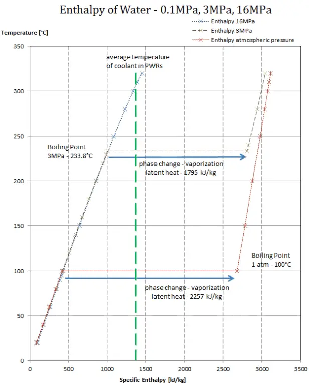
What is Boiling Mode – Type of Boiling – Definition

Boiling Modes – Types of Boiling. From a practical engineering point of view boiling can be categorized according to several criteria, for example, by the flow regime. Thermal Engineering

Boiling Modes – Types of Boiling

Pool Boiling - Boiling ModesFrom a practical engineering point of view boiling can be categorized according to several criteria.

Categorization by the flow regime:

  • Pool Boiling. Perhaps the most common configuration, known as pool boiling is when a pool of liquid is heated from below through a horizontal surface. In pool boiling the liquid is quiescent and its motion near the surface is primarily due to natural convection and to mixing induced by bubble growth and detachment. The pioneering work on pool boiling was done in 1934 by S. Nukiyama. He was the first to identify four well known different regimes of pool boiling using his apparatus.
  • Flow Boiling - Boiling ModesFlow Boiling. In flow boiling (or forced convection boiling), fluid flow is forced over a surface by external means such as a pump, as well as by buoyancy effects.  Therefore, flow boiling is always accompanied by other convection effects. Conditions depend strongly on geometry, which may involve external flow over heated plates and cylinders or internal (duct) flow. In nuclear reactors, most of boiling regimes are just forced convection boiling.

Categorization by the wall superheat temperature, ΔTsat:

Boiling Curve - Boiling ModesThe pioneering work on boiling was done in 1934 by S. Nukiyama, who used electrically heated nichrome and platinum wires immersed in liquids in his experiments. Nukiyama was the first to identify different regimes of pool boiling using his apparatus. He noticed that boiling takes different forms, depending on the value of the wall superheat temperature ΔTsat (known also as the excess temperature), which is defined as the difference between the wall temperature, Twall and the saturation temperature, Tsat.

Four different boiling regimes  of pool boiling (based on the excess temperature) are observed:

  • Natural Convection Boiling                            ΔTsat < 5°C
  • Nucleate Boiling                                   5°C < ΔTsat < 30°C
  • Transition Boiling                                 30°C < ΔTsat < 200°C
  • Film Boiling                                        200°C < ΔTsat

Description of Boiling Modes:

  • Natural Convection BoilingNatural Convection Boiling. In thermodynamics, the requirement for boiling of pure substances to occur is that Twall = Tsat. But in real experiments, boiling does not occur until the liquid is heated a few degrees above the saturation temperature. The surface temperature must be somewhat above the saturation temperature in order to sustain vapor formation. In this boiling mode, vapour will be observed over the water surface, but usually no bubbles will be observed. As the superheat temperature is increased, bubble inception will eventually occur, but below point A, fluid motion is determined principally by natural convection currents. The point A is usually referred to as the onset of nucleate boiling – ONB.
  • Nucleate Boiling - Boiling ModesNucleate Boiling. The most common type of local boiling encountered in nuclear facilities is nucleate boiling. In nucleate boiling, steam bubbles form at the heat transfer surface and then break away and are carried into the main stream of the fluid. Such movement enhances heat transfer because the heat generated at the surface is carried directly into the fluid stream. Once in the main fluid stream, the bubbles collapse because the bulk temperature of the fluid is not as high as the heat transfer surface temperature where the bubbles were created. This heat transfer process is sometimes desirable because the energy created at the heat transfer surface is quickly and efficiently “carried” away.
  • Transition Boiling - Partial Film BoilingTransition Boiling. The nucleate boiling heat flux cannot be increased indefinitely. At some value, we call it the “critical heat flux” (CHF), the steam produced can form an insulating layer over the surface, which in turn deteriorates the heat transfer coefficient. This is because a large fraction of the surface is covered by a vapor film, which acts as an thermal insulation due to the low thermal conductivity of the vapor relative to that of the liquid. Immediately after the critical heat flux has been reached, boiling become unstable and transition boiling occurs. The transition from nucleate boiling to film boiling is known as the “boiling crisis”. Since beyond the CHF point the heat transfer coefficient decreases, the transition to film boiling is usually inevitable.
  • Film Boiling - Boiling ModesFilm Boiling. A further increase in the heat flux causes a film of vapour to cover the surface. This significantly reduces the convection coefficient, since the vapor layer has significantly lower heat transfer ability. As a result the excess temperature shoots up to a very high value. Beyond the Leidenfrost point, a continuous vapor film blankets the surface and there is no contact between the liquid phase and the surface. In this situation the heat transfer is both by radiation and by conduction to the vapour. If the material is not strong enough for withstanding this temperature, the equipment will fail by damage to the material. This phenomenon is also known as burn out. In pressurized water reactors, one of key safety requirements (maybe the most important) is that a departure from nucleate boiling (DNB)  will not occur during steady state operation, normal operational transients, and anticipated operational occurrences (AOOs).  Fuel cladding integrity will be maintained if the minimum DNBR remains above the 95/95 DNBR limit for PWRs ( a 95% probability at a 95% confidence level). Since this phenomenon deteriorates the heat transfer coefficient and the heat flux remains, heat then accumulates in the fuel rod causing dramatic rise of cladding and fuel temperature. Simply, a very high temperature difference is required to transfer the critical heat flux being produced from the surface of the fuel rod to the reactor coolant (through vapor layer).

Subcooled Boiling - Boiling ModesCategorization by the subcooling temperature, ΔTsub.

Boiling may also be classified according to whether it is subcooled or saturated:

  • Subcooled boiling. In subcooled boiling, the temperature of most of the liquid is below the saturation temperature and bubbles formed at the surface may condense in the liquid. This condensation (collapsing) produces a sound of frequency ~ 100Hz – 1 KHz. This is why an electric kettle makes the most noise before the water comes to saturated boiling. The term subcooling refers to a liquid existing at a temperature below its normal boiling point.
  • Saturated Boiling. In saturated boiling (known also as bulk boiling), the temperature of the liquid slightly exceeds the saturation temperature. Bulk boiling may occur, when system temperature increases or system pressure drops to boiling point. At this point, the bubbles entering the coolant channel will not collapse. The bubbles will tend to join together and form bigger steam bubbles. Steam bubbles are then propelled through the liquid by buoyancy forces, eventually escaping from a free surface.

Saturated Boiling

 
Vapor Quality
dry-steam-saturated-vapor-minAs can be seen from the phase diagram of water, in the two-phase regions (e.g. on the border of vapor/liquid phases), specifying temperature alone will set the pressure and specifying pressure will set the temperature. But these parameters will not define the volume and enthalpy because we will need to know the relative proportion of the two phases present.

The mass fraction of the vapor in a two-phase liquid-vapor region is called the vapor quality (or dryness fraction), x, and it is given by following formula:

vapor quality

The value of the quality ranges from zero to unity. Although defined as a ratio, the quality is frequently given as a percentage. From this point of view, we distinguish between three basic types of  steam. It must be added, at x=0, we are talking about saturated liquid state (single-phase).

This classification of steam has its limitation. Consider the behavior of the system which is heated at the pressure, that is higher than the critical pressure. In this case, there would be no change in phase from liquid to steam. At all states there would be only one phase. Vaporization and condensation can occur only when the pressure is less than the critical pressure. The terms liquid and vapor tend to lose their significance.

See also: Saturation

See also: Throttling of Steam

Boiling

Phase diagram of water
Phase diagram of water.
Source: wikipedia.org CC BY-SA

In preceding chapters, we have discussed convective heat transfer with very important assumption. We have assumed a single-phase convective heat transfer without any phase change. In this chapter we focus on convective heat transfer associated with the change in phase of a fluid. In particular, we consider processes that can occur at a solid–liquid or solid–vapor interface, namely, boiling (liquid-to-vapor phase change) and condensation (vapor-to-liquid phase change).

For these cases latent heat effects associated with the phase change are significant. Latent heat, known also as the enthalpy of vaporization, is the amount of heat added to or removed from a substance to produce a change in phase. This energy breaks down the intermolecular attractive forces, and also must provide the energy necessary to expand the gas (the pΔV work). When latent heat is added, no temperature change occurs.

Latent heat of vaporization - water at 0.1 MPa, 3 MPa, 16 MPa
The heat of vaporization diminishes with increasing pressure, while the boiling point increases. It vanishes completely at a certain point called the critical point.

The enthalpy of vaporization is a function of the pressure at which that transformation takes place.

Latent heat of vaporization – water at 0.1 MPa (atmospheric pressure)

hlg = 2257 kJ/kg

Latent heat of vaporization – water at 3 MPa

hlg = 1795 kJ/kg

Latent heat of vaporization – water at 16 MPa (pressure inside a pressurizer)

hlg = 931 kJ/kg

The heat of vaporization diminishes with increasing pressure, while the boiling point increases. It vanishes completely at a certain point called the critical point. Above the critical point, the liquid and vapor phases are indistinguishable, and the substance is called a supercritical fluid.

supercritical-phase-critical-point-minThe change from the liquid to the vapor state due to boiling is sustained by heat transfer from the solid surface; conversely, condensation of a vapor to the liquid state results in heat transfer to the solid surface. Boiling and condensation differ from other forms of convection in that they depend on the latent heat of vaporization, which is very high for common pressures, therefore large amounts of heat can be transferred during boiling and condensation essentially at constant temperature. Heat transfer coefficients, h, associated with boiling and condensation are typically much higher than those encountered in other forms of convection processes that involve a single phase.

This is due to the fact, even in turbulent flow, there is a stagnant fluid film layer (laminar sublayer), that isolates the surface of the heat exchanger. This stagnant fluid film layer plays crucial role for the convective heat transfer coefficient. It is observed, that the fluid comes to a complete stop at the surface and assumes a zero velocity relative to the surface. This phenomenon is known as the no-slip condition and therefore, at the surface, energy flow occurs purely by conduction. But in the next layers both conduction and diffusion-mass movement in the molecular level or macroscopic level occurs. Due to the mass movement the rate of energy transfer is higher. As was written, nucleate boiling at the surface effectively disrupts this stagnant layer and therefore nucleate boiling significantly increases the ability of a surface to transfer thermal energy to bulk fluid.

 
Two-phase Fluid Flow
two-phase fluid flowBy definition, multiphase flow is the interactive flow of two or more distinct phases with common interfaces in, say, a conduit. Each phase, representing a volume fraction (or mass fraction) of solid, liquid or gaseous matter, has its own properties, velocity, and temperature.

A multiphase flow can be simultaneous flow of:

  • Materials with different states or phases (e.g. water-steam mixture).
  • Materials with different chemical properties but in the same state or phase (e.g. oil droplets in water).

There are many combinations in industrial processes, but the most common being the simultaneous flow of steam and liquid water (as encountered in steam generators and condensers). In reactor engineering a great deal of study has been performed on the nature of two-phase flow in case of a loss-of-coolant accident (LOCA), which is an accident of importance in reactor safety and in all thermal-hydraulic analyses (DNBR analyses).

Characteristics of Two-phase Fluid Flow

All two-phase flow problems have features which are characteristically different from those found in single-phase problems.

  • In the case of steam and liquid water the density of the two phases differs by a factor of about 1000. Therefore the influence of gravitational body force on multiphase flows is of much greater importance than in the case of single-phase flows.
  • The sound speed changes dramatically for materials undergoing phase change, and can be orders of magnitude different. This significantly influences a flow through an orifice.
  • The relative concentration of different phases is usually a dependent parameter of great importance in multiphase flows, while it is a parameter of no consequence in single-phase flows.
  • The change of phase means flow-induced pressure drops can cause further phase-change (e.g. water can evaporate through an orifice) increasing the relative volume of the gaseous, compressible medium and increasing efflux velocities, unlike single-phase incompressible flow where decreasing of an orifice would decrease efflux velocities.
  • The spatial distribution of the various phases in the flow channel strongly affects the flow behavior.
  • There are many types of instabilities in multiphase flow.
Boiling Point - Saturation
In thermodynamics, the term saturation defines a condition in which a mixture of vapor and liquid can exist together at a given temperature and pressure. The temperature at which vaporization (boiling) starts to occur for a given pressure is called the saturation temperature or boiling point. The pressure at which vaporization (boiling) starts to occur for a given temperature is called the saturation pressure.

When the vapor quality is equal to 0, it is referred to as the saturated liquid state (single-phase). On the other hand, when the vapor quality is equal to 1, it is referred to as the saturated vapor state or dry steam (single-phase). Between these two states, we talk about vapor-liquid mixture or wet steam (two-phase mixture). At constant pressure, an addition of energy does not changes the temperature of the mixture, but the vapor quality and specific volume changes.

 
References:
Heat Transfer:
  1. Fundamentals of Heat and Mass Transfer, 7th Edition. Theodore L. Bergman, Adrienne S. Lavine, Frank P. Incropera. John Wiley & Sons, Incorporated, 2011. ISBN: 9781118137253.
  2. Heat and Mass Transfer. Yunus A. Cengel. McGraw-Hill Education, 2011. ISBN: 9780071077866.
  3. U.S. Department of Energy, Thermodynamics, Heat Transfer and Fluid Flow. DOE Fundamentals Handbook, Volume 2 of 3. May 2016.

Nuclear and Reactor Physics:

  1. J. R. Lamarsh, Introduction to Nuclear Reactor Theory, 2nd ed., Addison-Wesley, Reading, MA (1983).
  2. J. R. Lamarsh, A. J. Baratta, Introduction to Nuclear Engineering, 3d ed., Prentice-Hall, 2001, ISBN: 0-201-82498-1.
  3. W. M. Stacey, Nuclear Reactor Physics, John Wiley & Sons, 2001, ISBN: 0- 471-39127-1.
  4. Glasstone, Sesonske. Nuclear Reactor Engineering: Reactor Systems Engineering, Springer; 4th edition, 1994, ISBN: 978-0412985317
  5. W.S.C. Williams. Nuclear and Particle Physics. Clarendon Press; 1 edition, 1991, ISBN: 978-0198520467
  6. G.R.Keepin. Physics of Nuclear Kinetics. Addison-Wesley Pub. Co; 1st edition, 1965
  7. Robert Reed Burn, Introduction to Nuclear Reactor Operation, 1988.
  8. U.S. Department of Energy, Nuclear Physics and Reactor Theory. DOE Fundamentals Handbook, Volume 1 and 2. January 1993.
  9. Paul Reuss, Neutron Physics. EDP Sciences, 2008. ISBN: 978-2759800414.

Advanced Reactor Physics:

  1. K. O. Ott, W. A. Bezella, Introductory Nuclear Reactor Statics, American Nuclear Society, Revised edition (1989), 1989, ISBN: 0-894-48033-2.
  2. K. O. Ott, R. J. Neuhold, Introductory Nuclear Reactor Dynamics, American Nuclear Society, 1985, ISBN: 0-894-48029-4.
  3. D. L. Hetrick, Dynamics of Nuclear Reactors, American Nuclear Society, 1993, ISBN: 0-894-48453-2.
  4. E. E. Lewis, W. F. Miller, Computational Methods of Neutron Transport, American Nuclear Society, 1993, ISBN: 0-894-48452-4.

See also:

Boiling and Condensation

We hope, this article, Boiling Mode – Type of Boiling, helps you. If so, give us a like in the sidebar. Main purpose of this website is to help the public to learn some interesting and important information about thermal engineering.