Facebook Instagram Youtube Twitter

What is Type of Steam Turbines – Definition

Types of Steam Turbines. Steam turbines may be classified into different categories depending on their construction, working pressures, size and many other parameters. Thermal Engineering

Types of Steam Turbines
Steam Turbine - types

Steam turbines may be classified into different categories depending on their construction, working pressures, size and many other parameters. But there are two basic types of steam turbines:

  • impulse turbines
  • reaction turbines.

The main distinction is the manner in which the steam is expanded as it passes through the turbine.

Impulse Turbine and Reaction Turbine

Steam turbine types based on blade geometry and energy conversion process are impulse turbine and reaction turbine.
Steam Turbine - Types of Turbine

Impulse Turbine

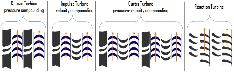
Steam TurbineThe impulse turbine is composed of moving blades alternating with fixed nozzles. In the impulse turbine, the steam is expanded in fixed nozzles and remains at constant pressure when passing over the blades. Curtis turbine, Rateau turbine, or Brown-Curtis turbine are impulse type turbines. The original steam turbine, the De Laval, was an impulse turbine having a single-blade wheel.

The entire pressure drop of steam take place in stationary nozzles only. Though the theoretical impulse blades have zero pressure drop in the moving blades, practically, for the flow to take place across the moving blades, there must be a small pressure drop across the moving blades also.
Impulse vs Reaction Turbine - comparison
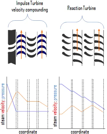
Impulse vs Reaction Turbine – comparison

In impulse turbines, the steam expands through the nozzle, where most of the pressure potential energy is converted to kinetic energy. The high-velocity steam from fixed nozzles impacts the blades, changes its direction, which in turn applies a force. The resulting impulse drives the blades forward, causing the rotor to turn. The main feature of these turbines is that the pressure drop per single stage can be quite large, allowing for large blades and a smaller number of stages. Except for low-power applications, turbine blades are arranged in multiple stages in series, called compounding, which greatly improves efficiency at low speeds.

Modern steam turbines frequently employ both reaction and impulse in the same unit, typically varying the degree of reaction and impulse from the blade root to its periphery. The rotor blades are usually designed like an impulse blade at the rot and like a reaction blade at the tip.
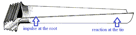
Turbine Blade - Impulse and Reaction
Impulse-Reaction Blade

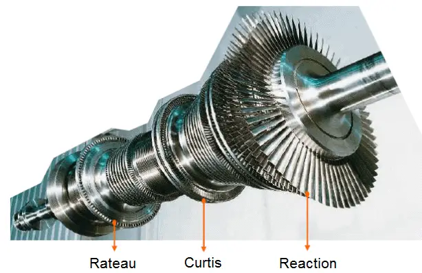
Since the Curtis stages reduce significantly the pressure and temperature of the fluid to a moderate level with a high proportion of work per stage. An usual arrangement is to provide on the high pressure side one or more Curtis stages, followed by Rateau or reaction staging. In general, when friction is taken into account reaction stages the reaction stage is found to be the most efficient, followed by Rateau and Curtis in that order. Frictional losses are significant for Curtis stages, since these are proportional to steam velocity squared. The reason that frictional losses are less significant in the reaction stage lies in the fact that the steam expands continuously and therefore flow velocities are lower.

 
Compounding of Steam Turbines
Compounding of steam turbines is the method in which energy from the steam is extracted in a number of stages rather than a single stage in a turbine. In all turbines the rotating blade velocity is proportional to the steam velocity passing over the blade. If the steam is expanded only in a single stage from the boiler pressure to the exhaust pressure, its velocity must be extremely high.

A compounded steam turbine has multiple stages i.e. it has more than one set of nozzles and rotors, in series, keyed to the shaft or fixed to the casing, so that either the steam pressure or the jet velocity is absorbed by the turbine in number of stages. For example, large HP Turbine used in nuclear power plants can be double-flow reaction turbine with about 10 stages with shrouded blades. Large LP turbines used in nuclear power plants are usually double-flow reaction turbines with about 5-8 stages (with shrouded blades and with free-standing blades of last 3 stages).

In an impulse steam turbine compounding can be achieved in the following three ways:

  • pressure compounding
  • velocity compounding
  • pressure-velocity compounding

Steam Turbine - Types of Turbine

Velocity Compounding
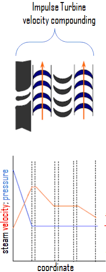
Impulse Turbine - velocity compounding
Impulse Turbine – velocity compounding

A velocity-compounded impulse stage consist of a row of fixed nozzles followed by two or more rows of moving blades and fixed blades (without expansion).  This divides the velocity drop across the stage into several smaller drops. In this type, the total pressure drop (expansion) of the steam take place only in the first nozzle ring. This produces very high velocity steam, which flows through multiple stages of fixed and moving blades. At each stage, only a portion of the high velocity is absorbed, the remainder is exhausted on to the next ring of fixed blades. The function of the fixed blades is to redirect the steam (without appreciably altering the velocity) leaving from the first ring of moving blades to the second ring of moving blades. The jet then passes on to the next ring of moving blades, the process repeating itself until practically all the velocity of the jet has been absorbed.

This method of velocity compounding is used to solve the problem of single stage impulse turbine for use of high pressure steam (i.e. required velocity of the turbine), but they are less efficient due to high friction losses.
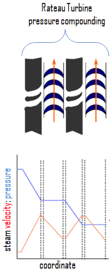
Pressure Compounding - Rateau Turbine - Zoelly Turbine
Rateau Turbine - pressure compounding
Rateau Turbine – pressure compounding

A pressure-compounded impulse stage is a row of fixed nozzles followed by a row of moving blades, with multiple stages for compounding. In this type, the total pressure drop of the steam does not take place in the first nozzle ring, but is divided up between all the nozzle rings. The effect of absorbing the pressure drop in stages is to reduce the velocity of the steam entering the moving blades. The steam from the boiler is passed through the first nozzle ring in which it is only partially expanded. It then passes over the first moving blade ring where nearly all of its velocity (momentum) is absorbed. From this ring it exhausts into the next nozzle ring and is again partially expanded. This method of pressure compounding is used in Rateau and Zoelly turbines, but such turbines are bigger and bulkier in size.
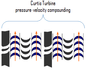
Pressure-Velocity Compounding - Curtis Turbine
Curtis Turbine - pressure-velocity compounding
Curtis Turbine – pressure-velocity compounding

Impulse stages may be either pressure-compounded, velocity-compounded, or pressure-velocity compounded. The pressure-velocity compounding is a combination of the above two types of compounding.  In fact, a series of velocity-compounded impulse stages is called a pressure-velocity compounded turbine. Each stage consists of rings of fixed and moving blades. Each set of rings of moving blades is separated by a single ring of fixed nozzles. In each stage there is one ring of fixed nozzles and 3-4 rings of moving blades (with fixed blades between them). Each stage acts as a velocity compounded impulse turbine.

The steam coming from the steam generator is passed to the first ring of fixed nozzles, where it gets partially expanded. The pressure partially decreases and the velocity rises correspondingly. It then passes over the 3-4 rings of moving blades (with fixed blades between them) where nearly all of its velocity is absorbed. From the last ring of the stage it exhausts into the next nozzle ring and is again partially expanded.

This has the advantage of allowing a bigger pressure drop in each stage and, consequently, less stages are necessary, resulting in a shorter turbine for a given pressure drop. It may be seen that the pressure is constant during each stage; the turbine is, therefore, an impulse turbine. The method of pressure-velocity compounding is used in the Curtis turbine.

Reaction Turbine – Parsons Turbine
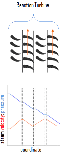
Reaction Turbine - schemaThe reaction turbine is composed of moving blades (nozzles) alternating with fixed nozzles. In the reaction turbine, the steam is expanded in fixed nozzles and also in the moving nozzles. In other words, the steam is continually expanding as it flows over the blades. There is pressure and velocity loss in the moving blades. The moving blades have a converging steam nozzle. Hence when the steam passes over the fixed blades, it expands with decrease in steam pressure and increase in kinetic energy.

In reaction turbines, the steam expands through the fixed nozzle , where the pressure potential energy is converted to kinetic energy. The high-velocity steam from fixed nozzles impacts the blades (nozzles), changes its direction and undergo further expansion. The change in its direction and the steam acceleration applies a force. The resulting impulse drives the blades forward, causing the rotor to turn. Ther is no net change in steam velocity across the stage but with a decrease in both pressure and temperature, reflecting the work performed in the driving of the rotor. In this type of turbine the pressure drops take place in a number of stages, because the pressure drop in a single stage is limited.

The main feature of this type of turbine is that in contrast to the impulse turbine, the pressure drop per stage is lower, so the blades become smaller and the number of stages increases. On the other hand, reaction turbines are usually more efficient, i.e. they have higher “isentropic turbine efficiency”. The reaction turbine was invented by Sir Charles Parsons and is known as the Parsons turbine.

In the case of steam turbines, such as would be used for electricity generation, a reaction turbine would require approximately double the number of blade rows as an impulse turbine, for the same degree of thermal energy conversion. Whilst this makes the reaction turbine much longer and heavier, the overall efficiency of a reaction turbine is slightly higher than the equivalent impulse turbine for the same thermal energy conversion.

Modern steam turbines frequently employ both reaction and impulse in the same unit, typically varying the degree of reaction and impulse from the blade root to its periphery. The rotor blades are usually designed like an impulse blade at the rot and like a reaction blade at the tip.

Turbine Blade - Impulse and Reaction

 
Pressure Compounding of Reaction Turbine
Compounding of steam turbines is the method in which energy from the steam is extracted in a number of stages rather than a single stage in a turbine. In all turbines the rotating blade velocity is proportional to the steam velocity passing over the blade. If the steam is expanded only in a single stage from the boiler pressure to the exhaust pressure, its velocity must be extremely high.

A compounded steam turbine has multiple stages i.e. it has more than one set of nozzles and blades, in series, keyed to the shaft or fixed to the casing, so that either the steam pressure or the jet velocity is absorbed by the turbine in number of stages. For example, large HP Turbine used in nuclear power plants can be double-flow reaction turbine with about 10 stages with shrouded blades. Large LP turbines used in nuclear power plants are usually double-flow reaction turbines with about 5-8 stages (with shrouded blades and with free-standing blades of last 3 stages).

In a reaction steam turbine compounding can be achieved only in the pressure compounding. In fact, it is not exactly the same as what it was discussed in impulse turbines. Note that, there is steam expansion in both the fixed and moving blades.

Classification of Turbines – steam supply and exhaust conditions

Steam turbines may be classified into different categories depending on their purpose and working pressures. The industrial usage of a turbine influences the initial and final conditions of steam. For any steam turbine to operate, a pressure difference must exist between the steam supply and the exhaust.

This classification includes:
 
Condensing Steam Turbine
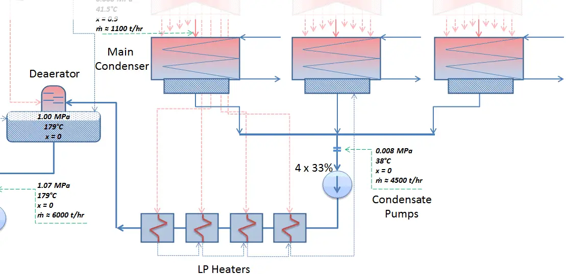
Condenser - LP Heaters - Deaerator

Condensing steam turbines are most commonly found in thermal power plants. In a condensing steam turbine, the maximum amount of energy is extracted from the steam, because there is very high enthalpy difference between the initial (e.g. 6MPa; 275°C; x = 1) and final (e.g. 0.008MPa; 41.5°C; x = 0.9) conditions of steam. This is achieved by passing the exhaust steam into a condenser (called a surface condenser), which condenses the exhaust steam from the low-pressure stages of the main turbine (decreases the temperature and pressure of exhausted steam). The exhausted steam is condensed by passing over tubes containing water from the cooling system.
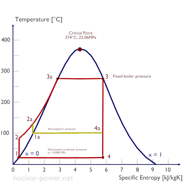
Rankine Cycle - condenser pressure
Decreasing the turbine exhaust pressure increases the net work per cycle but also decreses the vapor quality of outlet steam.

The goal of maintaining the lowest practical turbine exhaust pressure is a primary reason for including the condenser in a thermal power plant. The condenser provides a vacuum that maximizes the energy extracted from the steam, resulting in a significant increase in net work and thermal efficiency. But also this parameter (condenser pressure) has its engineering limits:

  • Decreasing the turbine exhaust pressure decreases the vapor quality (or dryness fraction). At some point the expansion must be ended to avoid damages that could be caused to blades of steam turbine by low quality steam.
  • Decreasing the turbine exhaust pressure significantly increases the specific volume of exhausted steam, which requires huge blades in last rows of low-pressure stage of the steam turbine.

In a typical condensing steam turbine, the exhausted steam condenses in the condenser and it is at a pressure well below atmospheric (absolute pressure of 0.008 MPa, which corresponds to 41.5°C). This steam is in a partially condensed state (point F), typically of a quality near 90%. Note that, the pressure inside the condenser is also dependent on the ambient atmospheric conditions:

  • air temperature, pressure and humidity in case of cooling into the atmosphere
  • water temperature and the flow rate in case of cooling into a river or sea

An increase in the ambient temperature causes a proportional increase in pressure of exhausted steam (ΔT = 14°C is usually a constant) hence the thermal efficiency of the power conversion system decreases. In other words, the electrical output of a power plant may vary with ambient conditions, while the thermal power remains constant.

The pressure inside condenser is given by the ambient air temperature (i.e. temperature of water in the cooling system) and by steam ejectors or vacuum pumps, which pull the gases (non-condensibles) from the surface condenser and eject them to the atmosphere.

The lowest feasible condenser pressure is the saturation pressure corresponding to the ambient temperature (e.g. absolute pressure of 0.008 MPa, which corresponds to 41.5°C). Note that, there is always a temperature difference between (around ΔT = 14°C) the condenser temperature and the ambient temperature, which originates from finite size and efficiency of condensers.
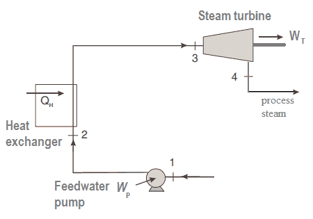
Back-pressure Steam Turbine
Back-pressure steam turbine - schema
Back-pressure steam turbine – schema

Back-pressure steam turbines or non-condensing turbines are most widely used for process steam applications. Steam is a principle energy source for many industrial processes. The popularity of process steam as an energy source stems from its many advantages, which include:

  • high heat capacity,
  • transportability
  • low toxicity

The process steam can be produced by back-pressure steam turbines, which also generates mechanical work (or electrical energy).  Back-pressure turbines expand the live steam supplied by the boiler to the pressure at which the steam is required for the process. The exhaust pressure is controlled by a regulating valve to suit the needs of the process steam pressure. Back-pressure turbines are commonly found at refineries, district heating units, pulp and paper plants, and desalination facilities where large amounts of low pressure process steam are needed. The electric power generated by the back-pressure turbine is directly proportional to the amount of process steam required.

Reheat Steam Turbine
Rankine cycle - reheat - superheat
Rankine cycle with reheat and superheat the low-pressure stage

Reheat turbines are also used almost exclusively in thermal power plants. All turbines, that have high-pressure turbine and low-pressure turbines use a steam reheat between these stages. Reheat allows to deliver more of the heat at a temperature close to the peak of the cycle (i.e. thermal efficiency increases). This requires the addition of another type of heat exchanger called a reheater.  The use of the reheater involves splitting the turbine, i.e. use of a multistage turbine with a reheater.  It was observed that more than two stages of reheating are unnecessary, since the next stage increases the cycle efficiency only half as much as the preceding stage.

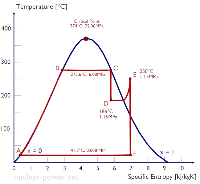
High pressure and low pressure stages of the turbine are usually on the same shaft to drive a common generator, but they have separate cases. With a reheater, the flow is extracted after a partial expansion (point D), run back through the heat exchanger to heat it back up to the peak temperature (point E), and then passed to the low-pressure turbine. The expansion is then completed in the low-pressure turbine from point E to point F.

The steam must be reheated or superheated in order to avoid damages that could be caused to blades of steam turbine by low quality steam. High content of water droplets can cause the rapid impingement and erosion of the blades which occurs when condensed water is blasted onto the blades. To prevent this, condensate drains are installed in the steam piping leading to the turbine. The reheater heats the steam (point D) and then the steam is directed to the low-pressure stage of steam turbine, where expands (point E to F). The exhausted steam is at a pressure well below atmospheric, and, as can be seen from the picture, the steam is in a partially condensed state (point F), typically of a quality near 90%, but it is much higher vapor quality, than that it would be without reheat. Accordingly, superheating also tends to alleviate the problem of low vapor quality at the turbine exhaust.
Wet Steam Turbine - Expansion

Turbine with Steam Extraction
Extraction type turbines are common in all applications. In some applications, when required, steam can be extracted from turbine before steam flowing through the last stage, named extraction turbine. As in back-pressure turbines, extracted steam can be used for many industrial processes or it can be used to improve the efficiency of thermodynamic cycle. The second case is usually known as the heat regeneration.

Almost all large steam turbines use the heat regeneration (i.e. they are extraction turbines), since it reduces the amount of fuel that must be added in the boiler. The reduction in the heat added can be done by transferring heat (partially expanded steam) from certain sections of the steam turbine, which is normally well above the ambient temperature, to the feedwater. Note that, most of energy contained in the steam is in the form of latent heat of vaporization. Extraction flows may be controlled with a valve, or left uncontrolled.

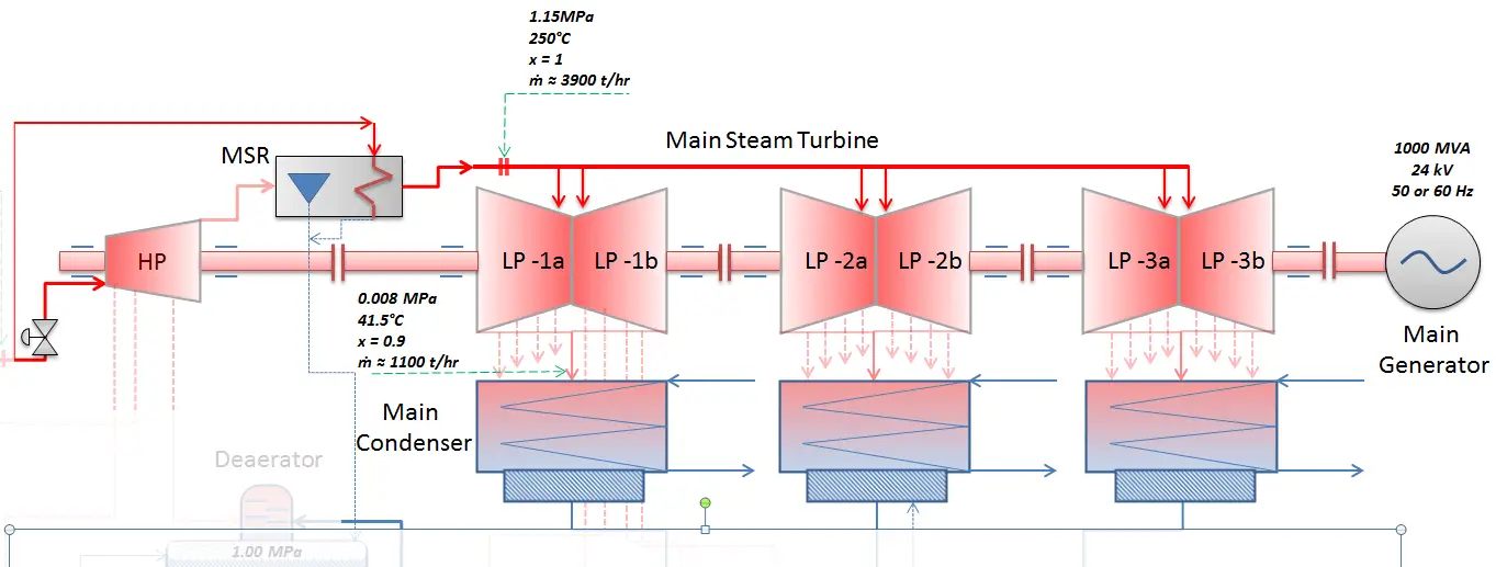
For example, most of nuclear power plants operates a single-shaft turbine-generator that consists of one multi-stage HP turbine with 3 or 4 self-regulating extraction lines and three parallel multi-stage LP turbines with 3 or 4 self-regulating extraction lines.

The high pressure feedwater heaters are usually heated by extraction steam from the high pressure turbine, HP, whereas the low-pressure feedwater heaters are usually heated by extraction steam from the low pressure turbine, LP. Both are usually self-regulating. It means that the greater the flow of feedwater the greater the rate of heat absorption from the steam and the greater the flow of extraction steam.
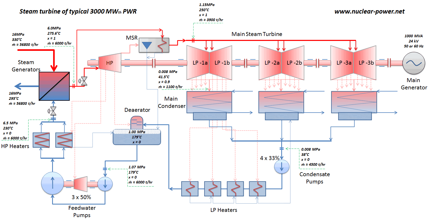
Steam turbine of typical 3000MWth PWR
Schema of a steam turbine of a typical 3000MWth PWR.
 
References:
Reactor Physics and Thermal Hydraulics:
  1. J. R. Lamarsh, Introduction to Nuclear Reactor Theory, 2nd ed., Addison-Wesley, Reading, MA (1983).
  2. J. R. Lamarsh, A. J. Baratta, Introduction to Nuclear Engineering, 3d ed., Prentice-Hall, 2001, ISBN: 0-201-82498-1.
  3. W. M. Stacey, Nuclear Reactor Physics, John Wiley & Sons, 2001, ISBN: 0- 471-39127-1.
  4. Glasstone, Sesonske. Nuclear Reactor Engineering: Reactor Systems Engineering, Springer; 4th edition, 1994, ISBN: 978-0412985317
  5. Todreas Neil E., Kazimi Mujid S. Nuclear Systems Volume I: Thermal Hydraulic Fundamentals, Second Edition. CRC Press; 2 edition, 2012, ISBN: 978-0415802871
  6. Zohuri B., McDaniel P. Thermodynamics in Nuclear Power Plant Systems. Springer; 2015, ISBN: 978-3-319-13419-2
  7. Moran Michal J., Shapiro Howard N. Fundamentals of Engineering Thermodynamics, Fifth Edition, John Wiley & Sons, 2006, ISBN: 978-0-470-03037-0
  8. Kleinstreuer C. Modern Fluid Dynamics. Springer, 2010, ISBN 978-1-4020-8670-0.
  9. U.S. Department of Energy, THERMODYNAMICS, HEAT TRANSFER, AND FLUID FLOW. DOE Fundamentals Handbook, Volume 1, 2 and 3. June 1992.
  10. U.S. NRC. NUREG-0800, Standard Review Plan for the Review of Safety Analysis Reports for Nuclear Power Plants: LWR Edition

See also:

Steam Turbine

We hope, this article, Type of Steam Turbines, helps you. If so, give us a like in the sidebar. Main purpose of this website is to help the public to learn some interesting and important information about thermal engineering.
What is Impulse Turbine and Reaction Turbine – Definition

There are two basic types of steam turbines: the impulse turbines and reaction turbines. The main distinction is the manner in which the steam is expanded through the turbine. Thermal Engineering

Impulse Turbine and Reaction Turbine

Steam Turbine - types

Steam turbines may be classified into different categories depending on their construction, working pressures, size and many other parameters. But there are two basic types of steam turbines:

  • impulse turbines
  • reaction turbines.

The main distinction is the manner in which the steam is expanded as it passes through the turbine.

Impulse Turbine and Reaction Turbine

Steam turbine types based on blade geometry and energy conversion process are impulse turbine and reaction turbine.

Steam Turbine - Types of Turbine

Impulse Turbine

Steam TurbineThe impulse turbine is composed of moving blades alternating with fixed nozzles. In the impulse turbine, the steam is expanded in fixed nozzles and remains at constant pressure when passing over the blades. Curtis turbine, Rateau turbine, or Brown-Curtis turbine are impulse type turbines. The original steam turbine, the De Laval, was an impulse turbine having a single-blade wheel.

The entire pressure drop of steam take place in stationary nozzles only. Though the theoretical impulse blades have zero pressure drop in the moving blades, practically, for the flow to take place across the moving blades, there must be a small pressure drop across the moving blades also.

Impulse vs Reaction Turbine - comparison
Impulse vs Reaction Turbine – comparison

In impulse turbines, the steam expands through the nozzle, where most of the pressure potential energy is converted to kinetic energy. The high-velocity steam from fixed nozzles impacts the blades, changes its direction, which in turn applies a force. The resulting impulse drives the blades forward, causing the rotor to turn. The main feature of these turbines is that the pressure drop per single stage can be quite large, allowing for large blades and a smaller number of stages. Except for low-power applications, turbine blades are arranged in multiple stages in series, called compounding, which greatly improves efficiency at low speeds.

Modern steam turbines frequently employ both reaction and impulse in the same unit, typically varying the degree of reaction and impulse from the blade root to its periphery. The rotor blades are usually designed like an impulse blade at the rot and like a reaction blade at the tip.

Turbine Blade - Impulse and Reaction
Impulse-Reaction Blade

Since the Curtis stages reduce significantly the pressure and temperature of the fluid to a moderate level with a high proportion of work per stage. An usual arrangement is to provide on the high pressure side one or more Curtis stages, followed by Rateau or reaction staging. In general, when friction is taken into account reaction stages the reaction stage is found to be the most efficient, followed by Rateau and Curtis in that order. Frictional losses are significant for Curtis stages, since these are proportional to steam velocity squared. The reason that frictional losses are less significant in the reaction stage lies in the fact that the steam expands continuously and therefore flow velocities are lower.

 
Compounding of Steam Turbines
Compounding of steam turbines is the method in which energy from the steam is extracted in a number of stages rather than a single stage in a turbine. In all turbines the rotating blade velocity is proportional to the steam velocity passing over the blade. If the steam is expanded only in a single stage from the boiler pressure to the exhaust pressure, its velocity must be extremely high.

A compounded steam turbine has multiple stages i.e. it has more than one set of nozzles and rotors, in series, keyed to the shaft or fixed to the casing, so that either the steam pressure or the jet velocity is absorbed by the turbine in number of stages. For example, large HP Turbine used in nuclear power plants can be double-flow reaction turbine with about 10 stages with shrouded blades. Large LP turbines used in nuclear power plants are usually double-flow reaction turbines with about 5-8 stages (with shrouded blades and with free-standing blades of last 3 stages).

In an impulse steam turbine compounding can be achieved in the following three ways:

  • pressure compounding
  • velocity compounding
  • pressure-velocity compounding

Steam Turbine - Types of Turbine

Velocity Compounding
Impulse Turbine - velocity compounding
Impulse Turbine – velocity compounding

A velocity-compounded impulse stage consist of a row of fixed nozzles followed by two or more rows of moving blades and fixed blades (without expansion).  This divides the velocity drop across the stage into several smaller drops. In this type, the total pressure drop (expansion) of the steam take place only in the first nozzle ring. This produces very high velocity steam, which flows through multiple stages of fixed and moving blades. At each stage, only a portion of the high velocity is absorbed, the remainder is exhausted on to the next ring of fixed blades. The function of the fixed blades is to redirect the steam (without appreciably altering the velocity) leaving from the first ring of moving blades to the second ring of moving blades. The jet then passes on to the next ring of moving blades, the process repeating itself until practically all the velocity of the jet has been absorbed.

This method of velocity compounding is used to solve the problem of single stage impulse turbine for use of high pressure steam (i.e. required velocity of the turbine), but they are less efficient due to high friction losses.

Pressure Compounding - Rateau Turbine - Zoelly Turbine
Rateau Turbine - pressure compounding
Rateau Turbine – pressure compounding

A pressure-compounded impulse stage is a row of fixed nozzles followed by a row of moving blades, with multiple stages for compounding. In this type, the total pressure drop of the steam does not take place in the first nozzle ring, but is divided up between all the nozzle rings. The effect of absorbing the pressure drop in stages is to reduce the velocity of the steam entering the moving blades. The steam from the boiler is passed through the first nozzle ring in which it is only partially expanded. It then passes over the first moving blade ring where nearly all of its velocity (momentum) is absorbed. From this ring it exhausts into the next nozzle ring and is again partially expanded. This method of pressure compounding is used in Rateau and Zoelly turbines, but such turbines are bigger and bulkier in size.

Pressure-Velocity Compounding - Curtis Turbine
Curtis Turbine - pressure-velocity compounding
Curtis Turbine – pressure-velocity compounding

Impulse stages may be either pressure-compounded, velocity-compounded, or pressure-velocity compounded. The pressure-velocity compounding is a combination of the above two types of compounding.  In fact, a series of velocity-compounded impulse stages is called a pressure-velocity compounded turbine. Each stage consists of rings of fixed and moving blades. Each set of rings of moving blades is separated by a single ring of fixed nozzles. In each stage there is one ring of fixed nozzles and 3-4 rings of moving blades (with fixed blades between them). Each stage acts as a velocity compounded impulse turbine.

The steam coming from the steam generator is passed to the first ring of fixed nozzles, where it gets partially expanded. The pressure partially decreases and the velocity rises correspondingly. It then passes over the 3-4 rings of moving blades (with fixed blades between them) where nearly all of its velocity is absorbed. From the last ring of the stage it exhausts into the next nozzle ring and is again partially expanded.

This has the advantage of allowing a bigger pressure drop in each stage and, consequently, less stages are necessary, resulting in a shorter turbine for a given pressure drop. It may be seen that the pressure is constant during each stage; the turbine is, therefore, an impulse turbine. The method of pressure-velocity compounding is used in the Curtis turbine.

Reaction Turbine – Parsons Turbine

Reaction Turbine - schemaThe reaction turbine is composed of moving blades (nozzles) alternating with fixed nozzles. In the reaction turbine, the steam is expanded in fixed nozzles and also in the moving nozzles. In other words, the steam is continually expanding as it flows over the blades. There is pressure and velocity loss in the moving blades. The moving blades have a converging steam nozzle. Hence when the steam passes over the fixed blades, it expands with decrease in steam pressure and increase in kinetic energy.

In reaction turbines, the steam expands through the fixed nozzle , where the pressure potential energy is converted to kinetic energy. The high-velocity steam from fixed nozzles impacts the blades (nozzles), changes its direction and undergo further expansion. The change in its direction and the steam acceleration applies a force. The resulting impulse drives the blades forward, causing the rotor to turn. Ther is no net change in steam velocity across the stage but with a decrease in both pressure and temperature, reflecting the work performed in the driving of the rotor. In this type of turbine the pressure drops take place in a number of stages, because the pressure drop in a single stage is limited.

The main feature of this type of turbine is that in contrast to the impulse turbine, the pressure drop per stage is lower, so the blades become smaller and the number of stages increases. On the other hand, reaction turbines are usually more efficient, i.e. they have higher “isentropic turbine efficiency”. The reaction turbine was invented by Sir Charles Parsons and is known as the Parsons turbine.

In the case of steam turbines, such as would be used for electricity generation, a reaction turbine would require approximately double the number of blade rows as an impulse turbine, for the same degree of thermal energy conversion. Whilst this makes the reaction turbine much longer and heavier, the overall efficiency of a reaction turbine is slightly higher than the equivalent impulse turbine for the same thermal energy conversion.

Modern steam turbines frequently employ both reaction and impulse in the same unit, typically varying the degree of reaction and impulse from the blade root to its periphery. The rotor blades are usually designed like an impulse blade at the rot and like a reaction blade at the tip.

Turbine Blade - Impulse and Reaction

 
Pressure Compounding of Reaction Turbine
Compounding of steam turbines is the method in which energy from the steam is extracted in a number of stages rather than a single stage in a turbine. In all turbines the rotating blade velocity is proportional to the steam velocity passing over the blade. If the steam is expanded only in a single stage from the boiler pressure to the exhaust pressure, its velocity must be extremely high.

A compounded steam turbine has multiple stages i.e. it has more than one set of nozzles and blades, in series, keyed to the shaft or fixed to the casing, so that either the steam pressure or the jet velocity is absorbed by the turbine in number of stages. For example, large HP Turbine used in nuclear power plants can be double-flow reaction turbine with about 10 stages with shrouded blades. Large LP turbines used in nuclear power plants are usually double-flow reaction turbines with about 5-8 stages (with shrouded blades and with free-standing blades of last 3 stages).

In a reaction steam turbine compounding can be achieved only in the pressure compounding. In fact, it is not exactly the same as what it was discussed in impulse turbines. Note that, there is steam expansion in both the fixed and moving blades.

 
References:
Reactor Physics and Thermal Hydraulics:
  1. J. R. Lamarsh, Introduction to Nuclear Reactor Theory, 2nd ed., Addison-Wesley, Reading, MA (1983).
  2. J. R. Lamarsh, A. J. Baratta, Introduction to Nuclear Engineering, 3d ed., Prentice-Hall, 2001, ISBN: 0-201-82498-1.
  3. W. M. Stacey, Nuclear Reactor Physics, John Wiley & Sons, 2001, ISBN: 0- 471-39127-1.
  4. Glasstone, Sesonske. Nuclear Reactor Engineering: Reactor Systems Engineering, Springer; 4th edition, 1994, ISBN: 978-0412985317
  5. Todreas Neil E., Kazimi Mujid S. Nuclear Systems Volume I: Thermal Hydraulic Fundamentals, Second Edition. CRC Press; 2 edition, 2012, ISBN: 978-0415802871
  6. Zohuri B., McDaniel P. Thermodynamics in Nuclear Power Plant Systems. Springer; 2015, ISBN: 978-3-319-13419-2
  7. Moran Michal J., Shapiro Howard N. Fundamentals of Engineering Thermodynamics, Fifth Edition, John Wiley & Sons, 2006, ISBN: 978-0-470-03037-0
  8. Kleinstreuer C. Modern Fluid Dynamics. Springer, 2010, ISBN 978-1-4020-8670-0.
  9. U.S. Department of Energy, THERMODYNAMICS, HEAT TRANSFER, AND FLUID FLOW. DOE Fundamentals Handbook, Volume 1, 2 and 3. June 1992.
  10. U.S. NRC. NUREG-0800, Standard Review Plan for the Review of Safety Analysis Reports for Nuclear Power Plants: LWR Edition

See also:

Steam Turbine

We hope, this article, Impulse Turbine and Reaction Turbine, helps you. If so, give us a like in the sidebar. Main purpose of this website is to help the public to learn some interesting and important information about thermal engineering.
What is Impulse Turbine – Impulse Blading – Definition

The impulse turbine is composed of moving impulse blades alternating with fixed nozzles. In the impulse turbine, the steam is expanded only in fixed nozzles. Thermal Engineering

Types of Steam Turbines

Steam Turbine - types

Steam turbines may be classified into different categories depending on their construction, working pressures, size and many other parameters. But there are two basic types of steam turbines:

  • impulse turbines
  • reaction turbines.

The main distinction is the manner in which the steam is expanded as it passes through the turbine.

Impulse Turbine and Reaction Turbine

Steam turbine types based on blade geometry and energy conversion process are impulse turbine and reaction turbine.

Steam Turbine - Types of Turbine

Impulse Turbine

Steam TurbineThe impulse turbine is composed of moving blades alternating with fixed nozzles. In the impulse turbine, the steam is expanded in fixed nozzles and remains at constant pressure when passing over the blades. Curtis turbine, Rateau turbine, or Brown-Curtis turbine are impulse type turbines. The original steam turbine, the De Laval, was an impulse turbine having a single-blade wheel.

The entire pressure drop of steam take place in stationary nozzles only. Though the theoretical impulse blades have zero pressure drop in the moving blades, practically, for the flow to take place across the moving blades, there must be a small pressure drop across the moving blades also.

Impulse vs Reaction Turbine - comparison
Impulse vs Reaction Turbine – comparison

In impulse turbines, the steam expands through the nozzle, where most of the pressure potential energy is converted to kinetic energy. The high-velocity steam from fixed nozzles impacts the blades, changes its direction, which in turn applies a force. The resulting impulse drives the blades forward, causing the rotor to turn. The main feature of these turbines is that the pressure drop per single stage can be quite large, allowing for large blades and a smaller number of stages. Except for low-power applications, turbine blades are arranged in multiple stages in series, called compounding, which greatly improves efficiency at low speeds.

Modern steam turbines frequently employ both reaction and impulse in the same unit, typically varying the degree of reaction and impulse from the blade root to its periphery. The rotor blades are usually designed like an impulse blade at the rot and like a reaction blade at the tip.

Turbine Blade - Impulse and Reaction
Impulse-Reaction Blade

Since the Curtis stages reduce significantly the pressure and temperature of the fluid to a moderate level with a high proportion of work per stage. An usual arrangement is to provide on the high pressure side one or more Curtis stages, followed by Rateau or reaction staging. In general, when friction is taken into account reaction stages the reaction stage is found to be the most efficient, followed by Rateau and Curtis in that order. Frictional losses are significant for Curtis stages, since these are proportional to steam velocity squared. The reason that frictional losses are less significant in the reaction stage lies in the fact that the steam expands continuously and therefore flow velocities are lower.

 
Compounding of Steam Turbines
Compounding of steam turbines is the method in which energy from the steam is extracted in a number of stages rather than a single stage in a turbine. In all turbines the rotating blade velocity is proportional to the steam velocity passing over the blade. If the steam is expanded only in a single stage from the boiler pressure to the exhaust pressure, its velocity must be extremely high.

A compounded steam turbine has multiple stages i.e. it has more than one set of nozzles and rotors, in series, keyed to the shaft or fixed to the casing, so that either the steam pressure or the jet velocity is absorbed by the turbine in number of stages. For example, large HP Turbine used in nuclear power plants can be double-flow reaction turbine with about 10 stages with shrouded blades. Large LP turbines used in nuclear power plants are usually double-flow reaction turbines with about 5-8 stages (with shrouded blades and with free-standing blades of last 3 stages).

In an impulse steam turbine compounding can be achieved in the following three ways:

  • pressure compounding
  • velocity compounding
  • pressure-velocity compounding

Steam Turbine - Types of Turbine

Velocity Compounding
Impulse Turbine - velocity compounding
Impulse Turbine – velocity compounding

A velocity-compounded impulse stage consist of a row of fixed nozzles followed by two or more rows of moving blades and fixed blades (without expansion).  This divides the velocity drop across the stage into several smaller drops. In this type, the total pressure drop (expansion) of the steam take place only in the first nozzle ring. This produces very high velocity steam, which flows through multiple stages of fixed and moving blades. At each stage, only a portion of the high velocity is absorbed, the remainder is exhausted on to the next ring of fixed blades. The function of the fixed blades is to redirect the steam (without appreciably altering the velocity) leaving from the first ring of moving blades to the second ring of moving blades. The jet then passes on to the next ring of moving blades, the process repeating itself until practically all the velocity of the jet has been absorbed.

This method of velocity compounding is used to solve the problem of single stage impulse turbine for use of high pressure steam (i.e. required velocity of the turbine), but they are less efficient due to high friction losses.

Pressure Compounding - Rateau Turbine - Zoelly Turbine
Rateau Turbine - pressure compounding
Rateau Turbine – pressure compounding

A pressure-compounded impulse stage is a row of fixed nozzles followed by a row of moving blades, with multiple stages for compounding. In this type, the total pressure drop of the steam does not take place in the first nozzle ring, but is divided up between all the nozzle rings. The effect of absorbing the pressure drop in stages is to reduce the velocity of the steam entering the moving blades. The steam from the boiler is passed through the first nozzle ring in which it is only partially expanded. It then passes over the first moving blade ring where nearly all of its velocity (momentum) is absorbed. From this ring it exhausts into the next nozzle ring and is again partially expanded. This method of pressure compounding is used in Rateau and Zoelly turbines, but such turbines are bigger and bulkier in size.

Pressure-Velocity Compounding - Curtis Turbine
Curtis Turbine - pressure-velocity compounding
Curtis Turbine – pressure-velocity compounding

Impulse stages may be either pressure-compounded, velocity-compounded, or pressure-velocity compounded. The pressure-velocity compounding is a combination of the above two types of compounding.  In fact, a series of velocity-compounded impulse stages is called a pressure-velocity compounded turbine. Each stage consists of rings of fixed and moving blades. Each set of rings of moving blades is separated by a single ring of fixed nozzles. In each stage there is one ring of fixed nozzles and 3-4 rings of moving blades (with fixed blades between them). Each stage acts as a velocity compounded impulse turbine.

The steam coming from the steam generator is passed to the first ring of fixed nozzles, where it gets partially expanded. The pressure partially decreases and the velocity rises correspondingly. It then passes over the 3-4 rings of moving blades (with fixed blades between them) where nearly all of its velocity is absorbed. From the last ring of the stage it exhausts into the next nozzle ring and is again partially expanded.

This has the advantage of allowing a bigger pressure drop in each stage and, consequently, less stages are necessary, resulting in a shorter turbine for a given pressure drop. It may be seen that the pressure is constant during each stage; the turbine is, therefore, an impulse turbine. The method of pressure-velocity compounding is used in the Curtis turbine.

 
References:
Reactor Physics and Thermal Hydraulics:
  1. J. R. Lamarsh, Introduction to Nuclear Reactor Theory, 2nd ed., Addison-Wesley, Reading, MA (1983).
  2. J. R. Lamarsh, A. J. Baratta, Introduction to Nuclear Engineering, 3d ed., Prentice-Hall, 2001, ISBN: 0-201-82498-1.
  3. W. M. Stacey, Nuclear Reactor Physics, John Wiley & Sons, 2001, ISBN: 0- 471-39127-1.
  4. Glasstone, Sesonske. Nuclear Reactor Engineering: Reactor Systems Engineering, Springer; 4th edition, 1994, ISBN: 978-0412985317
  5. Todreas Neil E., Kazimi Mujid S. Nuclear Systems Volume I: Thermal Hydraulic Fundamentals, Second Edition. CRC Press; 2 edition, 2012, ISBN: 978-0415802871
  6. Zohuri B., McDaniel P. Thermodynamics in Nuclear Power Plant Systems. Springer; 2015, ISBN: 978-3-319-13419-2
  7. Moran Michal J., Shapiro Howard N. Fundamentals of Engineering Thermodynamics, Fifth Edition, John Wiley & Sons, 2006, ISBN: 978-0-470-03037-0
  8. Kleinstreuer C. Modern Fluid Dynamics. Springer, 2010, ISBN 978-1-4020-8670-0.
  9. U.S. Department of Energy, THERMODYNAMICS, HEAT TRANSFER, AND FLUID FLOW. DOE Fundamentals Handbook, Volume 1, 2 and 3. June 1992.
  10. U.S. NRC. NUREG-0800, Standard Review Plan for the Review of Safety Analysis Reports for Nuclear Power Plants: LWR Edition

See also:

Steam Turbine

We hope, this article, Impulse Turbine – Impulse Blading, helps you. If so, give us a like in the sidebar. Main purpose of this website is to help the public to learn some interesting and important information about thermal engineering.
What is Compounding of Steam Turbines – Definition

Compounding of steam turbines is the method in which energy from the steam is extracted in a number of stages rather than a single stage in a turbine. Thermal Engineering

Compounding of Steam Turbines

Compounding of steam turbines is the method in which energy from the steam is extracted in a number of stages rather than a single stage in a turbine. In all turbines the rotating blade velocity is proportional to the steam velocity passing over the blade. If the steam is expanded only in a single stage from the boiler pressure to the exhaust pressure, its velocity must be extremely high.

A compounded steam turbine has multiple stages i.e. it has more than one set of nozzles and rotors, in series, keyed to the shaft or fixed to the casing, so that either the steam pressure or the jet velocity is absorbed by the turbine in number of stages. For example, large HP Turbine used in nuclear power plants can be double-flow reaction turbine with about 10 stages with shrouded blades. Large LP turbines used in nuclear power plants are usually double-flow reaction turbines with about 5-8 stages (with shrouded blades and with free-standing blades of last 3 stages).

In an impulse steam turbine compounding can be achieved in the following three ways:

  • pressure compounding
  • velocity compounding
  • pressure-velocity compounding

Steam Turbine - Types of Turbine

 
Velocity Compounding
Impulse Turbine - velocity compounding
Impulse Turbine – velocity compounding

A velocity-compounded impulse stage consist of a row of fixed nozzles followed by two or more rows of moving blades and fixed blades (without expansion).  This divides the velocity drop across the stage into several smaller drops. In this type, the total pressure drop (expansion) of the steam take place only in the first nozzle ring. This produces very high velocity steam, which flows through multiple stages of fixed and moving blades. At each stage, only a portion of the high velocity is absorbed, the remainder is exhausted on to the next ring of fixed blades. The function of the fixed blades is to redirect the steam (without appreciably altering the velocity) leaving from the first ring of moving blades to the second ring of moving blades. The jet then passes on to the next ring of moving blades, the process repeating itself until practically all the velocity of the jet has been absorbed.

This method of velocity compounding is used to solve the problem of single stage impulse turbine for use of high pressure steam (i.e. required velocity of the turbine), but they are less efficient due to high friction losses.

Pressure Compounding - Rateau Turbine - Zoelly Turbine
Rateau Turbine - pressure compounding
Rateau Turbine – pressure compounding

A pressure-compounded impulse stage is a row of fixed nozzles followed by a row of moving blades, with multiple stages for compounding. In this type, the total pressure drop of the steam does not take place in the first nozzle ring, but is divided up between all the nozzle rings. The effect of absorbing the pressure drop in stages is to reduce the velocity of the steam entering the moving blades. The steam from the boiler is passed through the first nozzle ring in which it is only partially expanded. It then passes over the first moving blade ring where nearly all of its velocity (momentum) is absorbed. From this ring it exhausts into the next nozzle ring and is again partially expanded. This method of pressure compounding is used in Rateau and Zoelly turbines, but such turbines are bigger and bulkier in size.

Pressure-Velocity Compounding - Curtis Turbine
Curtis Turbine - pressure-velocity compounding
Curtis Turbine – pressure-velocity compounding

Impulse stages may be either pressure-compounded, velocity-compounded, or pressure-velocity compounded. The pressure-velocity compounding is a combination of the above two types of compounding.  In fact, a series of velocity-compounded impulse stages is called a pressure-velocity compounded turbine. Each stage consists of rings of fixed and moving blades. Each set of rings of moving blades is separated by a single ring of fixed nozzles. In each stage there is one ring of fixed nozzles and 3-4 rings of moving blades (with fixed blades between them). Each stage acts as a velocity compounded impulse turbine.

The steam coming from the steam generator is passed to the first ring of fixed nozzles, where it gets partially expanded. The pressure partially decreases and the velocity rises correspondingly. It then passes over the 3-4 rings of moving blades (with fixed blades between them) where nearly all of its velocity is absorbed. From the last ring of the stage it exhausts into the next nozzle ring and is again partially expanded.

This has the advantage of allowing a bigger pressure drop in each stage and, consequently, less stages are necessary, resulting in a shorter turbine for a given pressure drop. It may be seen that the pressure is constant during each stage; the turbine is, therefore, an impulse turbine. The method of pressure-velocity compounding is used in the Curtis turbine.

 
Pressure Compounding of Reaction Turbine
Compounding of steam turbines is the method in which energy from the steam is extracted in a number of stages rather than a single stage in a turbine. In all turbines the rotating blade velocity is proportional to the steam velocity passing over the blade. If the steam is expanded only in a single stage from the boiler pressure to the exhaust pressure, its velocity must be extremely high.

A compounded steam turbine has multiple stages i.e. it has more than one set of nozzles and blades, in series, keyed to the shaft or fixed to the casing, so that either the steam pressure or the jet velocity is absorbed by the turbine in number of stages. For example, large HP Turbine used in nuclear power plants can be double-flow reaction turbine with about 10 stages with shrouded blades. Large LP turbines used in nuclear power plants are usually double-flow reaction turbines with about 5-8 stages (with shrouded blades and with free-standing blades of last 3 stages).

In a reaction steam turbine compounding can be achieved only in the pressure compounding. In fact, it is not exactly the same as what it was discussed in impulse turbines. Note that, there is steam expansion in both the fixed and moving blades.

 
References:
Reactor Physics and Thermal Hydraulics:
  1. J. R. Lamarsh, Introduction to Nuclear Reactor Theory, 2nd ed., Addison-Wesley, Reading, MA (1983).
  2. J. R. Lamarsh, A. J. Baratta, Introduction to Nuclear Engineering, 3d ed., Prentice-Hall, 2001, ISBN: 0-201-82498-1.
  3. W. M. Stacey, Nuclear Reactor Physics, John Wiley & Sons, 2001, ISBN: 0- 471-39127-1.
  4. Glasstone, Sesonske. Nuclear Reactor Engineering: Reactor Systems Engineering, Springer; 4th edition, 1994, ISBN: 978-0412985317
  5. Todreas Neil E., Kazimi Mujid S. Nuclear Systems Volume I: Thermal Hydraulic Fundamentals, Second Edition. CRC Press; 2 edition, 2012, ISBN: 978-0415802871
  6. Zohuri B., McDaniel P. Thermodynamics in Nuclear Power Plant Systems. Springer; 2015, ISBN: 978-3-319-13419-2
  7. Moran Michal J., Shapiro Howard N. Fundamentals of Engineering Thermodynamics, Fifth Edition, John Wiley & Sons, 2006, ISBN: 978-0-470-03037-0
  8. Kleinstreuer C. Modern Fluid Dynamics. Springer, 2010, ISBN 978-1-4020-8670-0.
  9. U.S. Department of Energy, THERMODYNAMICS, HEAT TRANSFER, AND FLUID FLOW. DOE Fundamentals Handbook, Volume 1, 2 and 3. June 1992.
  10. U.S. NRC. NUREG-0800, Standard Review Plan for the Review of Safety Analysis Reports for Nuclear Power Plants: LWR Edition

See also:

Steam Turbine

We hope, this article, Compounding of Steam Turbines, helps you. If so, give us a like in the sidebar. Main purpose of this website is to help the public to learn some interesting and important information about thermal engineering.

What is Pressure Compounding – Rateau Turbine – Zoelly Turbine – Definition

Pressure Compounding – Rateau Turbine – Zoelly Turbine. A pressure-compounded impulse stage is a row of fixed nozzles followed by a row of moving blades, with multiple stages for compounding. Thermal Engineering

Pressure Compounding – Rateau Turbine – Zoelly Turbine

Rateau Turbine - pressure compounding
Rateau Turbine – pressure compounding

A pressure-compounded impulse stage is a row of fixed nozzles followed by a row of moving blades, with multiple stages for compounding. In this type, the total pressure drop of the steam does not take place in the first nozzle ring, but is divided up between all the nozzle rings. The effect of absorbing the pressure drop in stages is to reduce the velocity of the steam entering the moving blades. The steam from the boiler is passed through the first nozzle ring in which it is only partially expanded. It then passes over the first moving blade ring where nearly all of its velocity (momentum) is absorbed. From this ring it exhausts into the next nozzle ring and is again partially expanded. This method of pressure compounding is used in Rateau and Zoelly turbines, but such turbines are bigger and bulkier in size.

 
References:
Reactor Physics and Thermal Hydraulics:
  1. J. R. Lamarsh, Introduction to Nuclear Reactor Theory, 2nd ed., Addison-Wesley, Reading, MA (1983).
  2. J. R. Lamarsh, A. J. Baratta, Introduction to Nuclear Engineering, 3d ed., Prentice-Hall, 2001, ISBN: 0-201-82498-1.
  3. W. M. Stacey, Nuclear Reactor Physics, John Wiley & Sons, 2001, ISBN: 0- 471-39127-1.
  4. Glasstone, Sesonske. Nuclear Reactor Engineering: Reactor Systems Engineering, Springer; 4th edition, 1994, ISBN: 978-0412985317
  5. Todreas Neil E., Kazimi Mujid S. Nuclear Systems Volume I: Thermal Hydraulic Fundamentals, Second Edition. CRC Press; 2 edition, 2012, ISBN: 978-0415802871
  6. Zohuri B., McDaniel P. Thermodynamics in Nuclear Power Plant Systems. Springer; 2015, ISBN: 978-3-319-13419-2
  7. Moran Michal J., Shapiro Howard N. Fundamentals of Engineering Thermodynamics, Fifth Edition, John Wiley & Sons, 2006, ISBN: 978-0-470-03037-0
  8. Kleinstreuer C. Modern Fluid Dynamics. Springer, 2010, ISBN 978-1-4020-8670-0.
  9. U.S. Department of Energy, THERMODYNAMICS, HEAT TRANSFER, AND FLUID FLOW. DOE Fundamentals Handbook, Volume 1, 2 and 3. June 1992.
  10. U.S. NRC. NUREG-0800, Standard Review Plan for the Review of Safety Analysis Reports for Nuclear Power Plants: LWR Edition

See also:

Steam Turbine

We hope, this article, Pressure Compounding – Rateau Turbine – Zoelly Turbine, helps you. If so, give us a like in the sidebar. Main purpose of this website is to help the public to learn some interesting and important information about thermal engineering.

What is Pressure-Velocity Compounding – Curtis Turbine – Definition

The method of pressure-velocity compounding is used in the Curtis turbine. The pressure-velocity compounding is a combination of the above two types of compounding. Thermal Engineering

Pressure-Velocity Compounding – Curtis Turbine

Curtis Turbine - pressure-velocity compounding
Curtis Turbine – pressure-velocity compounding

Impulse stages may be either pressure-compounded, velocity-compounded, or pressure-velocity compounded. The pressure-velocity compounding is a combination of the above two types of compounding.  In fact, a series of velocity-compounded impulse stages is called a pressure-velocity compounded turbine. Each stage consists of rings of fixed and moving blades. Each set of rings of moving blades is separated by a single ring of fixed nozzles. In each stage there is one ring of fixed nozzles and 3-4 rings of moving blades (with fixed blades between them). Each stage acts as a velocity compounded impulse turbine.

The steam coming from the steam generator is passed to the first ring of fixed nozzles, where it gets partially expanded. The pressure partially decreases and the velocity rises correspondingly. It then passes over the 3-4 rings of moving blades (with fixed blades between them) where nearly all of its velocity is absorbed. From the last ring of the stage it exhausts into the next nozzle ring and is again partially expanded.

This has the advantage of allowing a bigger pressure drop in each stage and, consequently, less stages are necessary, resulting in a shorter turbine for a given pressure drop. It may be seen that the pressure is constant during each stage; the turbine is, therefore, an impulse turbine. The method of pressure-velocity compounding is used in the Curtis turbine.

 
References:
Reactor Physics and Thermal Hydraulics:
  1. J. R. Lamarsh, Introduction to Nuclear Reactor Theory, 2nd ed., Addison-Wesley, Reading, MA (1983).
  2. J. R. Lamarsh, A. J. Baratta, Introduction to Nuclear Engineering, 3d ed., Prentice-Hall, 2001, ISBN: 0-201-82498-1.
  3. W. M. Stacey, Nuclear Reactor Physics, John Wiley & Sons, 2001, ISBN: 0- 471-39127-1.
  4. Glasstone, Sesonske. Nuclear Reactor Engineering: Reactor Systems Engineering, Springer; 4th edition, 1994, ISBN: 978-0412985317
  5. Todreas Neil E., Kazimi Mujid S. Nuclear Systems Volume I: Thermal Hydraulic Fundamentals, Second Edition. CRC Press; 2 edition, 2012, ISBN: 978-0415802871
  6. Zohuri B., McDaniel P. Thermodynamics in Nuclear Power Plant Systems. Springer; 2015, ISBN: 978-3-319-13419-2
  7. Moran Michal J., Shapiro Howard N. Fundamentals of Engineering Thermodynamics, Fifth Edition, John Wiley & Sons, 2006, ISBN: 978-0-470-03037-0
  8. Kleinstreuer C. Modern Fluid Dynamics. Springer, 2010, ISBN 978-1-4020-8670-0.
  9. U.S. Department of Energy, THERMODYNAMICS, HEAT TRANSFER, AND FLUID FLOW. DOE Fundamentals Handbook, Volume 1, 2 and 3. June 1992.
  10. U.S. NRC. NUREG-0800, Standard Review Plan for the Review of Safety Analysis Reports for Nuclear Power Plants: LWR Edition

See also:

Steam Turbine

We hope, this article, Pressure-Velocity Compounding – Curtis Turbine, helps you. If so, give us a like in the sidebar. Main purpose of this website is to help the public to learn some interesting and important information about thermal engineering.

What is Reaction Turbine – Parsons Turbine – Definition

The reaction turbine is composed of moving blades (nozzles) alternating with fixed nozzles. The reaction turbine is also known as the Parsons turbine. Thermal Engineering

Reaction Turbine – Parsons Turbine

Reaction Turbine - schemaThe reaction turbine is composed of moving blades (nozzles) alternating with fixed nozzles. In the reaction turbine, the steam is expanded in fixed nozzles and also in the moving nozzles. In other words, the steam is continually expanding as it flows over the blades. There is pressure and velocity loss in the moving blades. The moving blades have a converging steam nozzle. Hence when the steam passes over the fixed blades, it expands with decrease in steam pressure and increase in kinetic energy.

In reaction turbines, the steam expands through the fixed nozzle , where the pressure potential energy is converted to kinetic energy. The high-velocity steam from fixed nozzles impacts the blades (nozzles), changes its direction and undergo further expansion. The change in its direction and the steam acceleration applies a force. The resulting impulse drives the blades forward, causing the rotor to turn. Ther is no net change in steam velocity across the stage but with a decrease in both pressure and temperature, reflecting the work performed in the driving of the rotor. In this type of turbine the pressure drops take place in a number of stages, because the pressure drop in a single stage is limited.

The main feature of this type of turbine is that in contrast to the impulse turbine, the pressure drop per stage is lower, so the blades become smaller and the number of stages increases. On the other hand, reaction turbines are usually more efficient, i.e. they have higher “isentropic turbine efficiency”. The reaction turbine was invented by Sir Charles Parsons and is known as the Parsons turbine.

In the case of steam turbines, such as would be used for electricity generation, a reaction turbine would require approximately double the number of blade rows as an impulse turbine, for the same degree of thermal energy conversion. Whilst this makes the reaction turbine much longer and heavier, the overall efficiency of a reaction turbine is slightly higher than the equivalent impulse turbine for the same thermal energy conversion.

Modern steam turbines frequently employ both reaction and impulse in the same unit, typically varying the degree of reaction and impulse from the blade root to its periphery. The rotor blades are usually designed like an impulse blade at the rot and like a reaction blade at the tip.

Turbine Blade - Impulse and Reaction

 
Pressure Compounding of Reaction Turbine
Compounding of steam turbines is the method in which energy from the steam is extracted in a number of stages rather than a single stage in a turbine. In all turbines the rotating blade velocity is proportional to the steam velocity passing over the blade. If the steam is expanded only in a single stage from the boiler pressure to the exhaust pressure, its velocity must be extremely high.

A compounded steam turbine has multiple stages i.e. it has more than one set of nozzles and blades, in series, keyed to the shaft or fixed to the casing, so that either the steam pressure or the jet velocity is absorbed by the turbine in number of stages. For example, large HP Turbine used in nuclear power plants can be double-flow reaction turbine with about 10 stages with shrouded blades. Large LP turbines used in nuclear power plants are usually double-flow reaction turbines with about 5-8 stages (with shrouded blades and with free-standing blades of last 3 stages).

In a reaction steam turbine compounding can be achieved only in the pressure compounding. In fact, it is not exactly the same as what it was discussed in impulse turbines. Note that, there is steam expansion in both the fixed and moving blades.

 
References:
Reactor Physics and Thermal Hydraulics:
  1. J. R. Lamarsh, Introduction to Nuclear Reactor Theory, 2nd ed., Addison-Wesley, Reading, MA (1983).
  2. J. R. Lamarsh, A. J. Baratta, Introduction to Nuclear Engineering, 3d ed., Prentice-Hall, 2001, ISBN: 0-201-82498-1.
  3. W. M. Stacey, Nuclear Reactor Physics, John Wiley & Sons, 2001, ISBN: 0- 471-39127-1.
  4. Glasstone, Sesonske. Nuclear Reactor Engineering: Reactor Systems Engineering, Springer; 4th edition, 1994, ISBN: 978-0412985317
  5. Todreas Neil E., Kazimi Mujid S. Nuclear Systems Volume I: Thermal Hydraulic Fundamentals, Second Edition. CRC Press; 2 edition, 2012, ISBN: 978-0415802871
  6. Zohuri B., McDaniel P. Thermodynamics in Nuclear Power Plant Systems. Springer; 2015, ISBN: 978-3-319-13419-2
  7. Moran Michal J., Shapiro Howard N. Fundamentals of Engineering Thermodynamics, Fifth Edition, John Wiley & Sons, 2006, ISBN: 978-0-470-03037-0
  8. Kleinstreuer C. Modern Fluid Dynamics. Springer, 2010, ISBN 978-1-4020-8670-0.
  9. U.S. Department of Energy, THERMODYNAMICS, HEAT TRANSFER, AND FLUID FLOW. DOE Fundamentals Handbook, Volume 1, 2 and 3. June 1992.
  10. U.S. NRC. NUREG-0800, Standard Review Plan for the Review of Safety Analysis Reports for Nuclear Power Plants: LWR Edition

See also:

Steam Turbine

We hope, this article, Reaction Turbine – Parsons Turbine, helps you. If so, give us a like in the sidebar. Main purpose of this website is to help the public to learn some interesting and important information about thermal engineering.

What is How does a steam turbine work – Definition

How does a steam turbine work? Most of nuclear power plants operates a single-shaft turbine-generator that consists of one multi-stage HP turbine and three parallel multi-stage LP turbines. Thermal Engineering

How does a steam turbine work?

The thermal energy contained in the steam is converted to the mechanical energy by expansion through the turbine. The expansion takes place through a series of fixed blades (nozzles), that orient the steam flow into high speed jets. These jets contain significant kinetic energy, which is converted into shaft rotation by the bucket-like shaped rotor blades, as the steam jet changes direction (see: Law of conversation of momentum). The steam jet, in moving over the curved surface of the blade, exerts a pressure on the blade owing to its centrifugal force. Each row of fixed nozzles and moving blades is called a stage. The blades rotate on the turbine rotor and the fixed blades are concentrically arranged within the circular turbine casing.

In all turbines the rotating blade velocity is proportional to the steam velocity passing over the blade. If the steam is expanded only in a single stage from the boiler pressure to the exhaust pressure, its velocity must be extremely high. But the typical main turbine in nuclear power plants, in which steam expands from pressures about 6 MPa to pressures about 0.008 MPa, operates at speeds about 3,000 RPM for 50 Hz systems for 2-pole generator.(or 1500RPM for 4-pole generator), and 1800 RPM for 60 Hz systems for 4-pole generator (or 3600 RPM for 2-pole generator). A single-blade ring would require very large blades and approximately 30 000 RPM, which is too high for practical purposes.

Therefore most of nuclear power plants operates a single-shaft turbine-generator that consists of one multi-stage HP turbine and three parallel multi-stage LP turbines, a main generator and an exciter.  HP Turbine is usually double-flow reaction turbine with about 10 stages with shrouded blades and produces about 30-40% of the gross power output of the power plant unit. LP turbines are usually double-flow reaction turbines with about 5-8 stages (with shrouded blades and with free-standing blades of last 3 stages). LP turbines produce approximately 60-70% of the gross power output of the power plant unit. Each turbine rotor is mounted on two bearings, i.e. there are double bearings between each turbine module.

In these turbines the high-pressure stage receives steam (this steam is nearly saturated steam – x = 0.995 – point C at the figure; 6 MPa; 275.6°C) from a steam generator and exhaust it to moisture separator-reheater (point D). The steam must be reheated in order to avoid damages that could be caused to blades of steam turbine by low quality steam. The reheater heats the steam (point D) and then the steam is directed to the low-pressure stage of steam turbine, where expands (point E to F). The exhausted steam then condenses in the condenser and it is at a pressure well below atmospheric (absolute pressure of 0.008 MPa), and is in a partially condensed state (point F), typically of a quality near 90%.

Steam turbine of typical 3000MWth PWR
Schema of a steam turbine of a typical 3000MWth PWR.
Rateau Turbine - pressure compounding
Rateau Turbine – pressure compounding
Steam Turbine
Steam Turbine. Source wikipedia.org License: CC BY-SA 3.0
Rankine Cycle - Ts diagram
Rankine cycle – Ts diagram
 
Advantages and Disadvantages of Steam Turbines
Advantages
  • Since the steam turbine is a rotary heat engine, it is particularly suited to be used to drive an electrical generator.
  • Thermal efficiency of a steam turbine is usually higher than that of a reciprocating engine.
  • Very high power-to-weight ratio, compared to reciprocating engines.
  • Fewer moving parts than reciprocating engines.
  • Steam turbines are suitable for large thermal power plants. They are made in a variety of sizes up to 1.5 GW (2,000,000 hp) turbines used to generate electricity.
  • In general, steam contains high amount of enthalpy (espacially in the form of heat of vaporization). This implies lower mass flow rates compared to gas turbines.
  • In general, turbine moves in one direction only, with far less vibration than a reciprocating engine.
  • Steam turbines have greater reliability, particularly in applications where sustained high power output is required.

Disadvantages

Although approximately 90% of all electricity generation in the world is by use of steam turbines, they have also some disadvantages.

  • Relatively high overnight cost.
  • Steam turbines are less efficient than reciprocating engines at part load operation.
  • They have longer startup than gas turbines and surely than reciprocating engines.
  • Less responsive to changes in power demand compared with gas turbines and with reciprocating engines.
 
References:
Reactor Physics and Thermal Hydraulics:
  1. J. R. Lamarsh, Introduction to Nuclear Reactor Theory, 2nd ed., Addison-Wesley, Reading, MA (1983).
  2. J. R. Lamarsh, A. J. Baratta, Introduction to Nuclear Engineering, 3d ed., Prentice-Hall, 2001, ISBN: 0-201-82498-1.
  3. W. M. Stacey, Nuclear Reactor Physics, John Wiley & Sons, 2001, ISBN: 0- 471-39127-1.
  4. Glasstone, Sesonske. Nuclear Reactor Engineering: Reactor Systems Engineering, Springer; 4th edition, 1994, ISBN: 978-0412985317
  5. Todreas Neil E., Kazimi Mujid S. Nuclear Systems Volume I: Thermal Hydraulic Fundamentals, Second Edition. CRC Press; 2 edition, 2012, ISBN: 978-0415802871
  6. Zohuri B., McDaniel P. Thermodynamics in Nuclear Power Plant Systems. Springer; 2015, ISBN: 978-3-319-13419-2
  7. Moran Michal J., Shapiro Howard N. Fundamentals of Engineering Thermodynamics, Fifth Edition, John Wiley & Sons, 2006, ISBN: 978-0-470-03037-0
  8. Kleinstreuer C. Modern Fluid Dynamics. Springer, 2010, ISBN 978-1-4020-8670-0.
  9. U.S. Department of Energy, THERMODYNAMICS, HEAT TRANSFER, AND FLUID FLOW. DOE Fundamentals Handbook, Volume 1, 2 and 3. June 1992.
  10. U.S. NRC. NUREG-0800, Standard Review Plan for the Review of Safety Analysis Reports for Nuclear Power Plants: LWR Edition

See also:

Steam Turbine

We hope, this article, How does a steam turbine work, helps you. If so, give us a like in the sidebar. Main purpose of this website is to help the public to learn some interesting and important information about thermal engineering.

What is Deaerator – Operating Principle – Definition

Deaerator is a device that is used for the removal of oxygen and other dissolved gases from the feedwater to steam generators. The deaerator is part of the feedwater heating system. Thermal Engineering

Deaerator

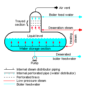
Deaerator
A schematic diagram of a typical tray-type deaerator. Source: wikipedia.org License: CC BY-SA 3.0

In general, a deaerator is a device that is used for the removal of oxygen and other dissolved gases from the feedwater to steam generators. The deaerator is part of the feedwater heating system. It is usually situated between the last low pressure heater and feedwater booster pumps. In particular, dissolved oxygen in the steam generator can cause serious corrosion damage by attaching to the walls of metal piping and other metallic equipment and forming oxides (rust). Furthermore, dissolved carbon dioxide combines with water to form carbonic acid that causes further corrosion.

In the deaerator, the condensate is heated to saturated conditions usually by the steam extracted from the steam turbine. The extraction steam are mixed in the deaerator by a system of spray nozzles and cascading trays between which the steam percolates. Any dissolved gases in the condensate are released in this process and removed from the deaerator by venting to the atmosphere or to the main condenser. Directly below the deaerator is the feedwater storage tank, in which a large quantity of feedwater is stored at near saturation conditions. In the turbine trip event, this feedwater can be supplied to steam generators to maintain the required water inventory during transient. The deaerator and the storage tank is usually located at a high elevation in the turbine hall to ensure an adequate net positive suction head (NPSH) at the inlet to the feedwater pumps. NPSH is used to measure how close a fluid is to saturated conditions. Lowering the pressure at the suction side can induce cavitation. This arrangement minimizes the risk of cavitation in the pump.

Steam turbine of typical 3000MWth PWR
Schema of a steam turbine of a typical 3000MWth PWR.
 
References:
Nuclear and Reactor Physics:
  1. J. R. Lamarsh, Introduction to Nuclear Reactor Theory, 2nd ed., Addison-Wesley, Reading, MA (1983).
  2. J. R. Lamarsh, A. J. Baratta, Introduction to Nuclear Engineering, 3d ed., Prentice-Hall, 2001, ISBN: 0-201-82498-1.
  3. W. M. Stacey, Nuclear Reactor Physics, John Wiley & Sons, 2001, ISBN: 0- 471-39127-1.
  4. Glasstone, Sesonske. Nuclear Reactor Engineering: Reactor Systems Engineering, Springer; 4th edition, 1994, ISBN: 978-0412985317
  5. W.S.C. Williams. Nuclear and Particle Physics. Clarendon Press; 1 edition, 1991, ISBN: 978-0198520467
  6. Kenneth S. Krane. Introductory Nuclear Physics, 3rd Edition, Wiley, 1987, ISBN: 978-0471805533
  7. G.R.Keepin. Physics of Nuclear Kinetics. Addison-Wesley Pub. Co; 1st edition, 1965
  8. Robert Reed Burn, Introduction to Nuclear Reactor Operation, 1988.
  9. U.S. Department of Energy, Nuclear Physics and Reactor Theory. DOE Fundamentals Handbook, Volume 1 and 2. January 1993.

Advanced Reactor Physics:

  1. K. O. Ott, W. A. Bezella, Introductory Nuclear Reactor Statics, American Nuclear Society, Revised edition (1989), 1989, ISBN: 0-894-48033-2.
  2. K. O. Ott, R. J. Neuhold, Introductory Nuclear Reactor Dynamics, American Nuclear Society, 1985, ISBN: 0-894-48029-4.
  3. D. L. Hetrick, Dynamics of Nuclear Reactors, American Nuclear Society, 1993, ISBN: 0-894-48453-2.
  4. E. E. Lewis, W. F. Miller, Computational Methods of Neutron Transport, American Nuclear Society, 1993, ISBN: 0-894-48452-4.

See also:

Turbine Generator

We hope, this article, Deaerator – Operating Principle, helps you. If so, give us a like in the sidebar. Main purpose of this website is to help the public to learn some interesting and important information about thermal engineering.

What is Turbine Bypass System – Turbine Steam Dump System – Definition

The turbine bypass system (TBS) or the turbine steam dump system provides operational flexibility so that the plant may accept certain load changes without disturbing the NSSS. Thermal Engineering

Turbine Bypass System – Turbine Steam Dump System

The turbine bypass system (TBS) or the turbine steam dump system provides operational flexibility so that the plant may accept certain load changes without disturbing the nuclear steam supply system (NSSS). The function of the turbine bypass system is to remove excess energy from the reactor coolant system by discharging a stated percentage of rated main steam flow directly to the main condensers, i.e. by bypassing the turbine. This heat is rejected to the condenser through the steam dump valves. The capacity of the system depends upon certain plant design, but it may be around 40 – 50% of nominal steam production. The steam dump valves automatically open under a sudden reduction in turbine-generator load or a turbine trip, which causes an increase in the system pressure.

In fact, the turbine bypass system usually corrects the system pressure of the power conversion unit. For example, during a turbine load reduction (e.g. caused by failure of 1/3 condensate pumps), the automatic reactor control system cannot reduce reactor thermal power as fast as the turbine power must decrease. Under these conditions, a power imbalance (NSSS / Turbine-Generator) results, with reactor power greater than the secondary system load (i.e. more heat is being added to the reactor coolant than that removed by the secondary via the steam generators). This power imbalance causes the pressure inside the steam generators to increase, which results in an increase in the temperature of the reactor coolant. Since the core inlet temperature is limited, the turbine bypass system is designed to establish the balance between the primary circuit and the secondary circuit, which limits this unwanted temperature increase.

The TBS is not a safety system, because it is not required for safe shutdown, as the relief and safety valves are operated under emergency conditions. The turbine bypass system is not required to function as a heat sink for the prevention or mitigation of postulated accidents. Failure of the TBS during a load reduction or turbine trip would result in the actuation of the relief valves and possibly the safety valves.

See also: NUREG-0800, Standard Review Plan for the Review of Safety Analysis Reports for Nuclear Power Plants: LWR Edition

The turbine bypass system is also used in the pressure control mode during plant cooldown, plant heatup and plant startup. For example, prior to synchronizing the generator to the grid, the reactor must be operated in the “power mode” (e.g. at 30% of rated power), while the steam production is bypassed to the condenser. The turbine bypass valves close automatically as steam is admitted to the turbine.

Turbine Bypass System - schema
Turbine Bypass System – schema
 
References:
Reactor Physics and Thermal Hydraulics:
  1. J. R. Lamarsh, Introduction to Nuclear Reactor Theory, 2nd ed., Addison-Wesley, Reading, MA (1983).
  2. J. R. Lamarsh, A. J. Baratta, Introduction to Nuclear Engineering, 3d ed., Prentice-Hall, 2001, ISBN: 0-201-82498-1.
  3. W. M. Stacey, Nuclear Reactor Physics, John Wiley & Sons, 2001, ISBN: 0- 471-39127-1.
  4. Glasstone, Sesonske. Nuclear Reactor Engineering: Reactor Systems Engineering, Springer; 4th edition, 1994, ISBN: 978-0412985317
  5. Todreas Neil E., Kazimi Mujid S. Nuclear Systems Volume I: Thermal Hydraulic Fundamentals, Second Edition. CRC Press; 2 edition, 2012, ISBN: 978-0415802871
  6. Zohuri B., McDaniel P. Thermodynamics in Nuclear Power Plant Systems. Springer; 2015, ISBN: 978-3-319-13419-2
  7. Moran Michal J., Shapiro Howard N. Fundamentals of Engineering Thermodynamics, Fifth Edition, John Wiley & Sons, 2006, ISBN: 978-0-470-03037-0
  8. Kleinstreuer C. Modern Fluid Dynamics. Springer, 2010, ISBN 978-1-4020-8670-0.
  9. U.S. Department of Energy, THERMODYNAMICS, HEAT TRANSFER, AND FLUID FLOW. DOE Fundamentals Handbook, Volume 1, 2 and 3. June 1992.
  10. U.S. NRC. NUREG-0800, Standard Review Plan for the Review of Safety Analysis Reports for Nuclear Power Plants: LWR Edition

See also:

Turbine Generator

We hope, this article, Turbine Bypass System – Turbine Steam Dump System, helps you. If so, give us a like in the sidebar. Main purpose of this website is to help the public to learn some interesting and important information about thermal engineering.