The Darcy–Weisbach equation is a phenomenological equation, which relates the major head loss due to fluid friction along a given length of pipe to the average velocity. Thermal Engineering
Darcy-Weisbach Equation
In fluid dynamics, the Darcy–Weisbach equation is a phenomenological equation, which relates the major head loss, or pressure loss, due to fluid friction along a given length of pipe to the average velocity. This equation is valid for fully developed, steady, incompressible single-phase flow.
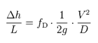
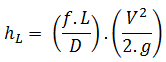
The Darcy–Weisbach equation can be written in two forms (pressure loss form or head loss form). In the head loss form can be written as:
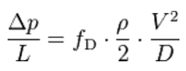
The Darcy–Weisbach equation in the pressure loss form can be written as:
where:
Δp = the pressure loss due to friction (Pa)
fD = the Darcy friction factor (unitless)
L = the pipe length (m)
D = the hydraulic diameter of the pipe D (m)
g = the gravitational constant (m/s2)
V = the mean flow velocity V (m/s)
___________
Evaluating the Darcy-Weisbach equation provides insight into factors affecting the head loss in a pipeline.
Consider that the length of the pipe or channel is doubled, the resulting frictional head loss will double.
At constant flow rate and pipe length, the head loss is inversely proportional to the 4th power of diameter (for laminar flow), and thus reducing the pipe diameter by half increases the head loss by a factor of 16. This is a very significant increase in head loss, and shows why larger diameter pipes lead to much smaller pumping power requirements.
Since the head loss is roughly proportional to the square of the flow rate, then if the flow rate is doubled, the head loss increases by a factor of four.
The head loss is reduced by half (for laminar flow) when the viscosity of the fluid is reduced by half.
Source: Donebythesecondlaw at the English language Wikipedia, CC BY-SA 3.0, https://commons.wikimedia.org/w/index.php?curid=4681366
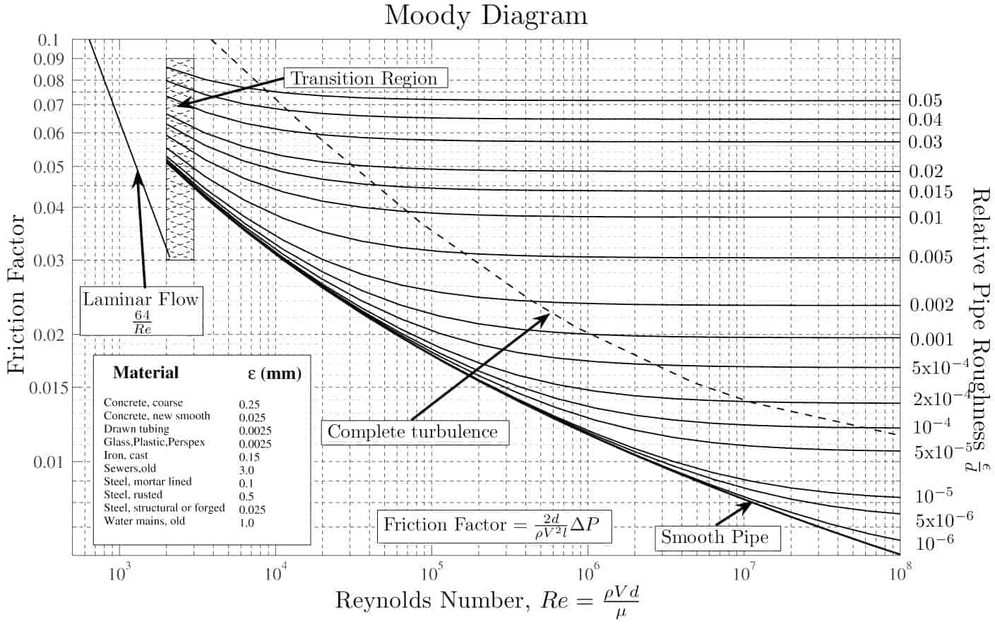
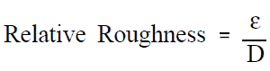
With the exception of the Darcy friction factor, each of these terms (the flow velocity, the hydraulic diameter, the length of a pipe) can be easily measured. The Darcy friction factor takes the fluid properties of density and viscosity into account, along with the pipe roughness. This factor may be evaluated by the use of various empirical relations, or it may be read from published charts (e.g. Moody chart).
Summary:
Head loss of hydraulic system is divided into two main categories:
Major Head Loss – due to friction in straight pipes
Minor Head Loss – due to components as valves, bends…
Darcy’s equation can be used to calculate major losses.
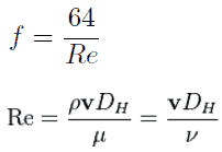
The friction factor for turbulent flow depends strongly on the relative roughness. It is determined by the Colebrook equation. It must be noted, at very large Reynolds numbers, the friction factor is independent of the Reynolds number.
Why the head loss is very important?
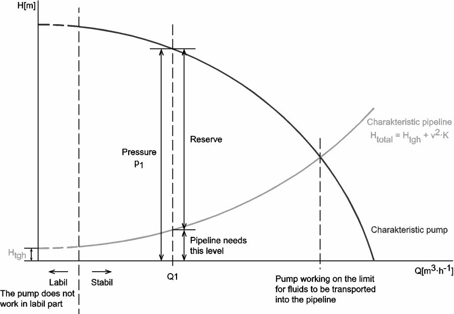
As can be seen from the picture, the head loss is forms key characteristic of any hydraulic system. In systems, in which some certain flowrate must be maintained (e.g. to provide sufficient cooling or heat transfer from a reactor core), the equilibrium of the head loss and the head added by a pump determines the flowrate through the system.
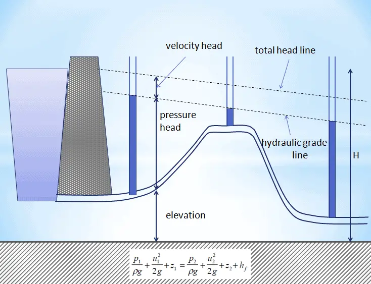
Q-H characteristic diagram of centrifugal pump and of pipelineHydraulic grade line and Total head lines for a constant diameter pipe with friction. In a real pipe line there are energy losses due to friction – these must be taken into account as they can be very significant.
Example: Frictional Head Loss
Water at 20°C is pumped through a smooth 12-cm-diameter pipe 10 km long, at a flow rate of 75 m3/h. The inlet is fed by a pump at an absolute pressure of 2.4 MPa.
The exit is at standard atmospheric pressure (101 kPa) and is 200 m higher.
Calculate the frictional head loss Hf, and compare it to the velocity head of the flow v2/(2g).
Solution:
Since the pipe diameter is constant, the average velocity and velocity head is the same everywhere:
Example: The head loss for one loop of primary piping
The primary circuit of typical PWRs is divided into 4 independent loops (piping diameter of about 700mm), each loop comprises a steam generator and one main coolant pump.
Assume that (this data do not represent any certain reactor design):
Inside the primary piping flows water at constant temperature of 290°C (⍴ ~ 720 kg/m3).
The kinematic viscosity of the water at 290°C is equal to 0.12 x 10⁻⁶ m2/s.
The primary piping flow velocity may be about 17 m/s.
The primary piping of one loop is about 20m long.
The Reynolds number inside the primary piping is equal to: ReD = 17 [m/s] x 0.7 [m] / 0.12×10⁻⁶ [m2/s] = 99 000 000
The Darcy friction factor is equal to fD = 0.01
Calculate the head loss for one loop of primary piping (without fitting, elbows, pumps etc.).
Solution:
Since we know all inputs of the Darcy-Weisbach equation, we can calculate the head loss directly:
Head loss form:
Δh = 0.01 x ½ x 1/9.81 x 20 x 172 / 0.7 = 4.2 m
Pressure loss form:
Δp = 0.01 x ½ x 720 x 20 x 172 / 0.7 = 29 725 Pa ≈ 0.03 MPa
Example: Change in head loss due to a decrease in viscosity.
In fully developed laminar flow in a circular pipe, the head loss is given by: where:
Since the Reynolds number is inverse proportional to viscosity, then the resulting head loss becomes proportional to viscosity. Therefore, the head loss is reduced by half when the viscosity of the fluid is reduced by half, when the flow rate and thus the average velocity are held constant.
References:
Reactor Physics and Thermal Hydraulics:
J. R. Lamarsh, Introduction to Nuclear Reactor Theory, 2nd ed., Addison-Wesley, Reading, MA (1983).
J. R. Lamarsh, A. J. Baratta, Introduction to Nuclear Engineering, 3d ed., Prentice-Hall, 2001, ISBN: 0-201-82498-1.
W. M. Stacey, Nuclear Reactor Physics, John Wiley & Sons, 2001, ISBN: 0- 471-39127-1.
Todreas Neil E., Kazimi Mujid S. Nuclear Systems Volume I: Thermal Hydraulic Fundamentals, Second Edition. CRC Press; 2 edition, 2012, ISBN: 978-0415802871
Zohuri B., McDaniel P. Thermodynamics in Nuclear Power Plant Systems. Springer; 2015, ISBN: 978-3-319-13419-2
Moran Michal J., Shapiro Howard N. Fundamentals of Engineering Thermodynamics, Fifth Edition, John Wiley & Sons, 2006, ISBN: 978-0-470-03037-0
Kleinstreuer C. Modern Fluid Dynamics. Springer, 2010, ISBN 978-1-4020-8670-0.
U.S. Department of Energy, THERMODYNAMICS, HEAT TRANSFER, AND FLUID FLOW. DOE Fundamentals Handbook, Volume 1, 2 and 3. June 1992.
White Frank M., Fluid Mechanics, McGraw-Hill Education, 7th edition, February, 2010, ISBN: 978-0077422417
See also:
Major Loss
We hope, this article, Darcy-Weisbach Equation, helps you. If so, give us a like in the sidebar. Main purpose of this website is to help the public to learn some interesting and important information about thermal engineering.
The Darcy friction factor is a dimensionless quantity used in the Darcy–Weisbach equation, for the description of frictional losses in pipe or duct as well as for open-channel flow. Thermal Engineering
Darcy-Weisbach Equation
In fluid dynamics, the Darcy–Weisbach equation is a phenomenological equation, which relates the major head loss, or pressure loss, due to fluid friction along a given length of pipe to the average velocity. This equation is valid for fully developed, steady, incompressible single-phase flow.
The Darcy–Weisbach equation can be written in two forms (pressure loss form or head loss form). In the head loss form can be written as:
Evaluating the Darcy-Weisbach equation provides insight into factors affecting the head loss in a pipeline.
Consider that the length of the pipe or channel is doubled, the resulting frictional head loss will double.
At constant flow rate and pipe length, the head loss is inversely proportional to the 4th power of diameter (for laminar flow), and thus reducing the pipe diameter by half increases the head loss by a factor of 16. This is a very significant increase in head loss, and shows why larger diameter pipes lead to much smaller pumping power requirements.
Since the head loss is roughly proportional to the square of the flow rate, then if the flow rate is doubled, the head loss increases by a factor of four.
The head loss is reduced by half (for laminar flow) when the viscosity of the fluid is reduced by half.
Source: Donebythesecondlaw at the English language Wikipedia, CC BY-SA 3.0, https://commons.wikimedia.org/w/index.php?curid=4681366
With the exception of the Darcy friction factor, each of these terms (the flow velocity, the hydraulic diameter, the length of a pipe) can be easily measured. The Darcy friction factor takes the fluid properties of density and viscosity into account, along with the pipe roughness. This factor may be evaluated by the use of various empirical relations, or it may be read from published charts (e.g. Moody chart).
[/su_accordion]
Darcy Friction Factor
There are two common friction factors in use, the Darcy and the Fanning friction factors.
Fanning Friction Factor
The Fanning friction factor, named after John Thomas Fanning, is a dimensionless number, that is one-fourth of the Darcy friction factor, so attention must be paid to note which one of these is used as the friction factor. This the only difference between these two factors. In all other aspects they are identical, and by applying the conversion factor of 4 the friction factors may be used interchangeably.
fD = 4.fF
[/su_accordion]The Darcy friction factor is a dimensionless quantity used in the Darcy–Weisbach equation, for the description of frictional losses in pipe or duct as well as for open-channel flow. This is also called the Darcy–Weisbach friction factor, resistance coefficient, or simply friction factor.
The friction factor has been determined to depend on the Reynolds number for the flow and the degree of roughness of the pipe’s inner surface (especially for turbulent flow). The friction factor of laminar flow is independent of roughness of the pipe’s inner surface.
The pipe cross-section is also important, as deviations from circular cross-section will cause secondary flows that increase the head loss. Non-circular pipes and ducts are generally treated by using the hydraulic diameter.
Relative Roughness
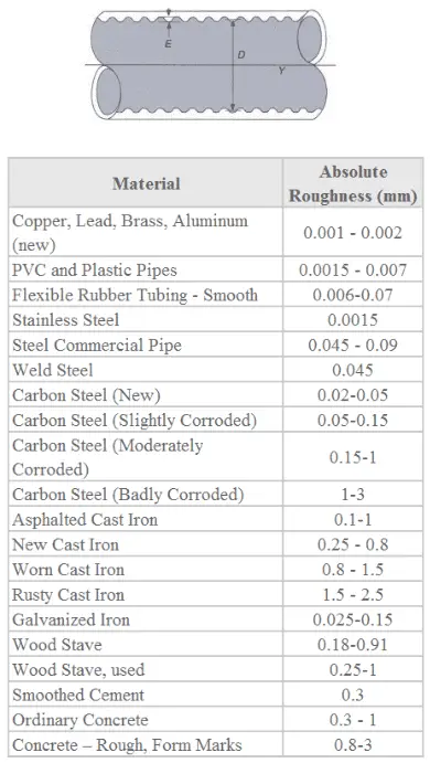
The quantity used to measure the roughness of the pipe’s inner surface is called the relative roughness, and it is equal to the average height of surface irregularities (ε) divided by the pipe diameter (D).
,where both the average height surface irregularities and the pipe diameter are in millimeters.
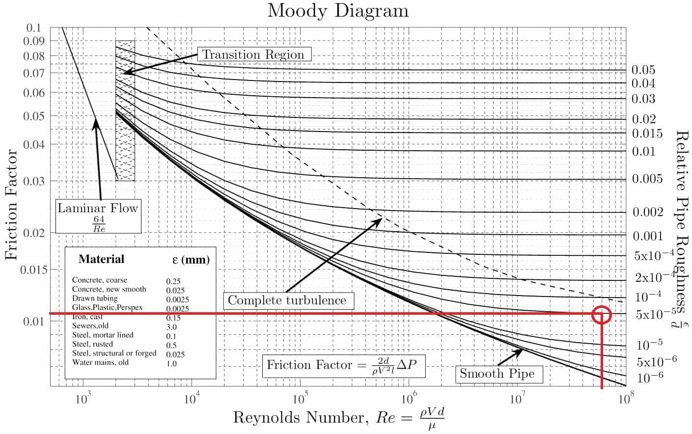
If we know the relative roughness of the pipe’s inner surface, then we can obtain the value of the friction factor from the Moody Chart.
The Moody chart (also known as the Moody diagram) is a graph in non-dimensional form that relates the Darcy friction factor, Reynolds number, and the relative roughness for fully developed flow in a circular pipe.
Summary:
Head loss of hydraulic system is divided into two main categories:
Major Head Loss – due to friction in straight pipes
Minor Head Loss – due to components as valves, bends…
Darcy’s equation can be used to calculate major losses.
The friction factor for turbulent flow depends strongly on the relative roughness. It is determined by the Colebrook equation. It must be noted, at very large Reynolds numbers, the friction factor is independent of the Reynolds number.
Why the head loss is very important?
As can be seen from the picture, the head loss is forms key characteristic of any hydraulic system. In systems, in which some certain flowrate must be maintained (e.g. to provide sufficient cooling or heat transfer from a reactor core), the equilibrium of the head loss and the head added by a pump determines the flowrate through the system.
Q-H characteristic diagram of centrifugal pump and of pipeline
Example: Moody Chart
Determine the friction factor (fD) for fluid flow in a pipe of 700mm in diameter that has the Reynolds number of 50 000 000 and an absolute roughness of 0.035 mm.
Solution:
The relative roughness is equal to ε = 0.035 / 700 = 5 x 10⁻⁵. Using the Moody Chart, a Reynolds number of 50 000 000 intersects the curve corresponding to a relative roughness of 5 x 10⁻⁵ at a friction factor of 0.011.
Example: Moody chart. Source: Donebythesecondlaw at the English language Wikipedia, CC BY-SA 3.0, https://commons.wikimedia.org/w/index.php?curid=4681366
Darcy Friction Factor for various flow regime
The most common classification of flow regimes is according to the Reynolds number. The Reynolds number is a dimensionless number comprised of the physical characteristics of the flow and it determines whether the flow is laminar or turbulent. An increasing Reynolds number indicates an increasing turbulence of flow. As can be seen from the Moody chart, also Darcy friction factor is highly dependent on the flow regime (i.e. on the Reynolds number).
Darcy Friction Factor for Laminar Flow
For practical purposes, if theReynolds number is less than 2000, the flow is laminar. The accepted transition Reynolds number for flow in a circular pipe is Red,crit = 2300. For laminar flow, the head loss is proportional to velocity rather than velocity squared, thus the friction factor is inversely proportional to velocity.
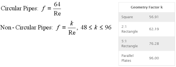
The Darcy friction factor for laminar (slow) flows is a consequence of Poiseuille’s law that and it is given by following equations:
Darcy Friction Factor for Transitional Flow
At Reynolds numbers between about 2000 and 4000 the flow is unstable as a result of the onset of turbulence. These flows are sometimes referred to as transitional flows. The Darcy friction factor contains large uncertainties in this flow regime and is not well understood.
Darcy Friction Factor for Turbulent Flow
If the Reynolds number is greater than 3500, the flow is turbulent. Most fluid systems in nuclear facilities operate with turbulent flow. In this flow regime the resistance to flow follows the Darcy–Weisbach equation: it is proportional to the square of the mean flow velocity. The Darcy friction factor depends strongly on the relative roughness of the pipe’s inner surface.
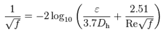
The most common method to determine a friction factor for turbulent flow is to use the Moody chart. The Moody chart (also known as the Moody diagram) is a log-log plot of the Colebrook correlation that relates the Darcy friction factor, Reynolds number, and the relative roughness for fully developed flow in a circular pipe. The Colebrook–White equation:
which is also known as the Colebrook equation, expresses the Darcy friction factor fas a function of pipe relative roughnessε / Dh and Reynolds number.
In 1939, Colebrook found an implicit correlation for the friction factor in round pipes by fitting the data of experimental studies of turbulent flow in smooth and rough pipes.
For hydraulically smooth pipe and the turbulent flow (Re < 105) the friction factor can be approximated by Blasius formula:
f = (100.Re)-¼
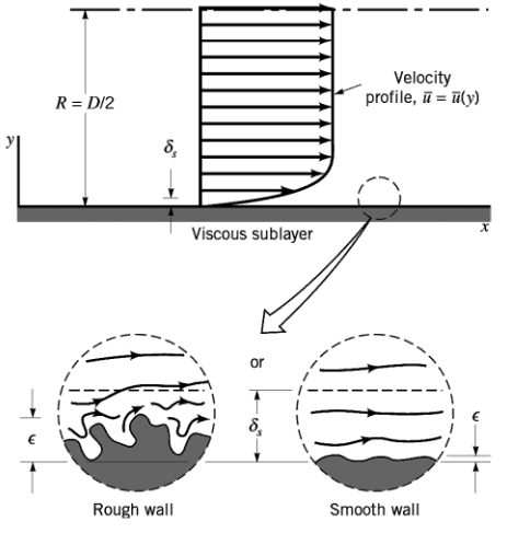
It must be noted, at very large Reynolds numbers, the friction factor is independent of the Reynolds number. This is because the thickness of laminar sublayer (viscous sublayer) decreases with increasing Reynolds number. For very large Reynolds numbers the thickness of laminar sublayer is comparable to the surface roughness and it directly influences the flow. The laminar sublayer becomes so thin that the surface roughness protrudes into the flow. The frictional losses in this case are produced in the main flow primarily by the protruding roughness elements, and the contribution of the laminar sublayer is negligible.
References:
Reactor Physics and Thermal Hydraulics:
J. R. Lamarsh, Introduction to Nuclear Reactor Theory, 2nd ed., Addison-Wesley, Reading, MA (1983).
J. R. Lamarsh, A. J. Baratta, Introduction to Nuclear Engineering, 3d ed., Prentice-Hall, 2001, ISBN: 0-201-82498-1.
W. M. Stacey, Nuclear Reactor Physics, John Wiley & Sons, 2001, ISBN: 0- 471-39127-1.
Todreas Neil E., Kazimi Mujid S. Nuclear Systems Volume I: Thermal Hydraulic Fundamentals, Second Edition. CRC Press; 2 edition, 2012, ISBN: 978-0415802871
Zohuri B., McDaniel P. Thermodynamics in Nuclear Power Plant Systems. Springer; 2015, ISBN: 978-3-319-13419-2
Moran Michal J., Shapiro Howard N. Fundamentals of Engineering Thermodynamics, Fifth Edition, John Wiley & Sons, 2006, ISBN: 978-0-470-03037-0
Kleinstreuer C. Modern Fluid Dynamics. Springer, 2010, ISBN 978-1-4020-8670-0.
U.S. Department of Energy, THERMODYNAMICS, HEAT TRANSFER, AND FLUID FLOW. DOE Fundamentals Handbook, Volume 1, 2 and 3. June 1992.
White Frank M., Fluid Mechanics, McGraw-Hill Education, 7th edition, February, 2010, ISBN: 978-0077422417
See also:
Major Loss
We hope, this article, Darcy Friction Factor, helps you. If so, give us a like in the sidebar. Main purpose of this website is to help the public to learn some interesting and important information about thermal engineering.
The Fanning friction factor, named after John Thomas Fanning, is a dimensionless number, that is one-fourth of the Darcy friction factor. Fanning Friction Factor
Fanning Friction Factor
There are two common friction factors in use, the Darcy and the Fanning friction factors.
The Fanning friction factor, named after John Thomas Fanning, is a dimensionless number, that is one-fourth of the Darcy friction factor, so attention must be paid to note which one of these is used as the friction factor. This the only difference between these two factors. In all other aspects they are identical, and by applying the conversion factor of 4 the friction factors may be used interchangeably. fD = 4.fF
Darcy Friction Factor
The Darcy friction factor is a dimensionless quantity used in the Darcy–Weisbach equation, for the description of frictional losses in pipe or duct as well as for open-channel flow. This is also called the Darcy–Weisbach friction factor, resistance coefficient, or simply friction factor.
The friction factor has been determined to depend on the Reynolds number for the flow and the degree of roughness of the pipe’s inner surface (especially for turbulent flow). The friction factor of laminar flow is independent of roughness of the pipe’s inner surface.
The pipe cross-section is also important, as deviations from circular cross-section will cause secondary flows that increase the head loss. Non-circular pipes and ducts are generally treated by using the hydraulic diameter.
[/su_accordion]
Summary:
Head loss of hydraulic system is divided into two main categories:
Major Head Loss – due to friction in straight pipes
Minor Head Loss – due to components as valves, bends…
The friction factor for turbulent flow depends strongly on the relative roughness. It is determined by the Colebrook equation. It must be noted, at very large Reynolds numbers, the friction factor is independent of the Reynolds number.
The Darcy friction factor is a dimensionless quantity used in the Darcy–Weisbach equation, for the description of frictional losses in pipe or duct as well as for open-channel flow. This is also called the Darcy–Weisbach friction factor, resistance coefficient, or simply friction factor.
The friction factor has been determined to depend on the Reynolds number for the flow and the degree of roughness of the pipe’s inner surface (especially for turbulent flow). The friction factor of laminar flow is independent of roughness of the pipe’s inner surface.
The pipe cross-section is also important, as deviations from circular cross-section will cause secondary flows that increase the head loss. Non-circular pipes and ducts are generally treated by using the hydraulic diameter.
Relative Roughness
The quantity used to measure the roughness of the pipe’s inner surface is called the relative roughness, and it is equal to the average height of surface irregularities (ε) divided by the pipe diameter (D).
,where both the average height surface irregularities and the pipe diameter are in millimeters.
If we know the relative roughness of the pipe’s inner surface, then we can obtain the value of the friction factor from the Moody Chart.
The Moody chart (also known as the Moody diagram) is a graph in non-dimensional form that relates the Darcy friction factor, Reynolds number, and the relative roughness for fully developed flow in a circular pipe.
Example: Moody Chart
Determine the friction factor (fD) for fluid flow in a pipe of 700mm in diameter that has the Reynolds number of 50 000 000 and an absolute roughness of 0.035 mm.
Solution:
The relative roughness is equal to ε = 0.035 / 700 = 5 x 10⁻⁵. Using the Moody Chart, a Reynolds number of 50 000 000 intersects the curve corresponding to a relative roughness of 5 x 10⁻⁵ at a friction factor of 0.011.
Example: Moody chart. Source: Donebythesecondlaw at the English language Wikipedia, CC BY-SA 3.0, https://commons.wikimedia.org/w/index.php?curid=4681366
Darcy Friction Factor for various flow regime
The most common classification of flow regimes is according to the Reynolds number. The Reynolds number is a dimensionless number comprised of the physical characteristics of the flow and it determines whether the flow is laminar or turbulent. An increasing Reynolds number indicates an increasing turbulence of flow. As can be seen from the Moody chart, also Darcy friction factor is highly dependent on the flow regime (i.e. on the Reynolds number).
Darcy Friction Factor for Laminar Flow
For practical purposes, if theReynolds number is less than 2000, the flow is laminar. The accepted transition Reynolds number for flow in a circular pipe is Red,crit = 2300. For laminar flow, the head loss is proportional to velocity rather than velocity squared, thus the friction factor is inversely proportional to velocity.
The Darcy friction factor for laminar (slow) flows is a consequence of Poiseuille’s law that and it is given by following equations:
Darcy Friction Factor for Transitional Flow
At Reynolds numbers between about 2000 and 4000 the flow is unstable as a result of the onset of turbulence. These flows are sometimes referred to as transitional flows. The Darcy friction factor contains large uncertainties in this flow regime and is not well understood.
Darcy Friction Factor for Turbulent Flow
If the Reynolds number is greater than 3500, the flow is turbulent. Most fluid systems in nuclear facilities operate with turbulent flow. In this flow regime the resistance to flow follows the Darcy–Weisbach equation: it is proportional to the square of the mean flow velocity. The Darcy friction factor depends strongly on the relative roughness of the pipe’s inner surface.
The most common method to determine a friction factor for turbulent flow is to use the Moody chart. The Moody chart (also known as the Moody diagram) is a log-log plot of the Colebrook correlation that relates the Darcy friction factor, Reynolds number, and the relative roughness for fully developed flow in a circular pipe. The Colebrook–White equation:
which is also known as the Colebrook equation, expresses the Darcy friction factor fas a function of pipe relative roughnessε / Dh and Reynolds number.
In 1939, Colebrook found an implicit correlation for the friction factor in round pipes by fitting the data of experimental studies of turbulent flow in smooth and rough pipes.
For hydraulically smooth pipe and the turbulent flow (Re < 105) the friction factor can be approximated by Blasius formula:
f = (100.Re)-¼
It must be noted, at very large Reynolds numbers, the friction factor is independent of the Reynolds number. This is because the thickness of laminar sublayer (viscous sublayer) decreases with increasing Reynolds number. For very large Reynolds numbers the thickness of laminar sublayer is comparable to the surface roughness and it directly influences the flow. The laminar sublayer becomes so thin that the surface roughness protrudes into the flow. The frictional losses in this case are produced in the main flow primarily by the protruding roughness elements, and the contribution of the laminar sublayer is negligible.
Examples
Example: The head loss for one loop of primary piping
The primary circuit of typical PWRs is divided into 4 independent loops (piping diameter of about 700mm), each loop comprises a steam generator and one main coolant pump.
Assume that (this data do not represent any certain reactor design):
Inside the primary piping flows water at constant temperature of 290°C (⍴ ~ 720 kg/m3).
The kinematic viscosity of the water at 290°C is equal to 0.12 x 10⁻⁶ m2/s.
The primary piping flow velocity may be about 17 m/s.
The primary piping of one loop is about 20m long.
The Reynolds number inside the primary piping is equal to: ReD = 17 [m/s] x 0.7 [m] / 0.12×10⁻⁶ [m2/s] = 99 000 000
The Darcy friction factor is equal to fD = 0.01
Calculate the head loss for one loop of primary piping (without fitting, elbows, pumps etc.).
Solution:
Since we know all inputs of the Darcy-Weisbach equation, we can calculate the head loss directly:
Head loss form:
Δh = 0.01 x ½ x 1/9.81 x 20 x 172 / 0.7 = 4.2 m
Pressure loss form:
Δp = 0.01 x ½ x 720 x 20 x 172 / 0.7 = 29 725 Pa ≈ 0.03 MPa
Example: Change in head loss due to a decrease in viscosity.
In fully developed laminar flow in a circular pipe, the head loss is given by: where:
Since the Reynolds number is inverse proportional to viscosity, then the resulting head loss becomes proportional to viscosity. Therefore, the head loss is reduced by half when the viscosity of the fluid is reduced by half, when the flow rate and thus the average velocity are held constant.
References:
Reactor Physics and Thermal Hydraulics:
J. R. Lamarsh, Introduction to Nuclear Reactor Theory, 2nd ed., Addison-Wesley, Reading, MA (1983).
J. R. Lamarsh, A. J. Baratta, Introduction to Nuclear Engineering, 3d ed., Prentice-Hall, 2001, ISBN: 0-201-82498-1.
W. M. Stacey, Nuclear Reactor Physics, John Wiley & Sons, 2001, ISBN: 0- 471-39127-1.
Todreas Neil E., Kazimi Mujid S. Nuclear Systems Volume I: Thermal Hydraulic Fundamentals, Second Edition. CRC Press; 2 edition, 2012, ISBN: 978-0415802871
Zohuri B., McDaniel P. Thermodynamics in Nuclear Power Plant Systems. Springer; 2015, ISBN: 978-3-319-13419-2
Moran Michal J., Shapiro Howard N. Fundamentals of Engineering Thermodynamics, Fifth Edition, John Wiley & Sons, 2006, ISBN: 978-0-470-03037-0
Kleinstreuer C. Modern Fluid Dynamics. Springer, 2010, ISBN 978-1-4020-8670-0.
U.S. Department of Energy, THERMODYNAMICS, HEAT TRANSFER, AND FLUID FLOW. DOE Fundamentals Handbook, Volume 1, 2 and 3. June 1992.
White Frank M., Fluid Mechanics, McGraw-Hill Education, 7th edition, February, 2010, ISBN: 978-0077422417
See also:
Major Loss
We hope, this article, Fanning Friction Factor, helps you. If so, give us a like in the sidebar. Main purpose of this website is to help the public to learn some interesting and important information about thermal engineering.
The quantity used to measure the roughness of the pipe’s inner surface is called the relative roughness. It is equal to the height of surface irregularities (ε) divided by the pipe diameter (D). Thermal Engineering
Darcy Friction Factor
The Darcy friction factor is a dimensionless quantity used in the Darcy–Weisbach equation, for the description of frictional losses in pipe or duct as well as for open-channel flow. This is also called the Darcy–Weisbach friction factor, resistance coefficient, or simply friction factor.
The friction factor has been determined to depend on the Reynolds number for the flow and the degree of roughness of the pipe’s inner surface (especially for turbulent flow). The friction factor of laminar flow is independent of roughness of the pipe’s inner surface.
The pipe cross-section is also important, as deviations from circular cross-section will cause secondary flows that increase the head loss. Non-circular pipes and ducts are generally treated by using the hydraulic diameter.
[/su_accordion]
Relative Roughness
The quantity used to measure the roughness of the pipe’s inner surface is called the relative roughness, and it is equal to the average height of surface irregularities (ε) divided by the pipe diameter (D).
,where both the average height surface irregularities and the pipe diameter are in millimeters.
If we know the relative roughness of the pipe’s inner surface, then we can obtain the value of the friction factor from the Moody Chart.
The Moody chart (also known as the Moody diagram) is a graph in non-dimensional form that relates the Darcy friction factor, Reynolds number, and the relative roughness for fully developed flow in a circular pipe.
Summary:
Head loss of hydraulic system is divided into two main categories:
Major Head Loss – due to friction in straight pipes
Minor Head Loss – due to components as valves, bends…
The friction factor for turbulent flow depends strongly on the relative roughness. It is determined by the Colebrook equation. It must be noted, at very large Reynolds numbers, the friction factor is independent of the Reynolds number.
Why the head loss is very important?
As can be seen from the picture, the head loss is forms key characteristic of any hydraulic system. In systems, in which some certain flowrate must be maintained (e.g. to provide sufficient cooling or heat transfer from a reactor core), the equilibrium of the head loss and the head added by a pump determines the flowrate through the system.
Q-H characteristic diagram of centrifugal pump and of pipeline
Example: Moody Chart
Determine the friction factor (fD) for fluid flow in a pipe of 700mm in diameter that has the Reynolds number of 50 000 000 and an absolute roughness of 0.035 mm.
Solution:
The relative roughness is equal to ε = 0.035 / 700 = 5 x 10⁻⁵. Using the Moody Chart, a Reynolds number of 50 000 000 intersects the curve corresponding to a relative roughness of 5 x 10⁻⁵ at a friction factor of 0.011.
Example: Moody chart. Source: Donebythesecondlaw at the English language Wikipedia, CC BY-SA 3.0, https://commons.wikimedia.org/w/index.php?curid=4681366
It must be noted, at very large Reynolds numbers, the friction factor is independent of the Reynolds number. This is because the thickness of laminar sublayer (viscous sublayer) decreases with increasing Reynolds number. For very large Reynolds numbers the thickness of laminar sublayer is comparable to the surface roughness and it directly influences the flow. The laminar sublayer becomes so thin that the surface roughness protrudes into the flow. The frictional losses in this case are produced in the main flow primarily by the protruding roughness elements, and the contribution of the laminar sublayer is negligible.
References:
Reactor Physics and Thermal Hydraulics:
J. R. Lamarsh, Introduction to Nuclear Reactor Theory, 2nd ed., Addison-Wesley, Reading, MA (1983).
J. R. Lamarsh, A. J. Baratta, Introduction to Nuclear Engineering, 3d ed., Prentice-Hall, 2001, ISBN: 0-201-82498-1.
W. M. Stacey, Nuclear Reactor Physics, John Wiley & Sons, 2001, ISBN: 0- 471-39127-1.
Todreas Neil E., Kazimi Mujid S. Nuclear Systems Volume I: Thermal Hydraulic Fundamentals, Second Edition. CRC Press; 2 edition, 2012, ISBN: 978-0415802871
Zohuri B., McDaniel P. Thermodynamics in Nuclear Power Plant Systems. Springer; 2015, ISBN: 978-3-319-13419-2
Moran Michal J., Shapiro Howard N. Fundamentals of Engineering Thermodynamics, Fifth Edition, John Wiley & Sons, 2006, ISBN: 978-0-470-03037-0
Kleinstreuer C. Modern Fluid Dynamics. Springer, 2010, ISBN 978-1-4020-8670-0.
U.S. Department of Energy, THERMODYNAMICS, HEAT TRANSFER, AND FLUID FLOW. DOE Fundamentals Handbook, Volume 1, 2 and 3. June 1992.
White Frank M., Fluid Mechanics, McGraw-Hill Education, 7th edition, February, 2010, ISBN: 978-0077422417
See also:
Major Loss
We hope, this article, Relative Roughness of Pipe, helps you. If so, give us a like in the sidebar. Main purpose of this website is to help the public to learn some interesting and important information about thermal engineering.
The Moody diagram (also known as the Moody chart) is a graph in non-dimensional form that relates the Darcy friction factor, Reynolds number, and the relative roughness. Thermal Engineering
Source: Donebythesecondlaw at the English language Wikipedia, CC BY-SA 3.0, https://commons.wikimedia.org/w/index.php?curid=4681366
Darcy Friction Factor
The Darcy friction factor is a dimensionless quantity used in the Darcy–Weisbach equation, for the description of frictional losses in pipe or duct as well as for open-channel flow. This is also called the Darcy–Weisbach friction factor, resistance coefficient, or simply friction factor.
The friction factor has been determined to depend on the Reynolds number for the flow and the degree of roughness of the pipe’s inner surface (especially for turbulent flow). The friction factor of laminar flow is independent of roughness of the pipe’s inner surface.
The pipe cross-section is also important, as deviations from circular cross-section will cause secondary flows that increase the head loss. Non-circular pipes and ducts are generally treated by using the hydraulic diameter.
Relative Roughness
The quantity used to measure the roughness of the pipe’s inner surface is called the relative roughness, and it is equal to the average height of surface irregularities (ε) divided by the pipe diameter (D).
,where both the average height surface irregularities and the pipe diameter are in millimeters.
If we know the relative roughness of the pipe’s inner surface, then we can obtain the value of the friction factor from the Moody Chart.
The Moody chart (also known as the Moody diagram) is a graph in non-dimensional form that relates the Darcy friction factor, Reynolds number, and the relative roughness for fully developed flow in a circular pipe.
Reynolds Number
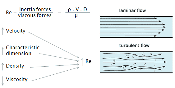
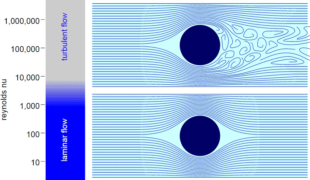
The Reynolds number is the ratio of inertial forces to viscous forces and is a convenient parameter for predicting if a flow condition will be laminar or turbulent. It can be interpreted that when the viscous forces are dominant (slow flow, low Re) they are sufficient enough to keep all the fluid particles in line, then the flow is laminar. Even very low Re indicates viscous creeping motion, where inertia effects are negligible. When the inertial forces dominate over the viscous forces (when the fluid is flowing faster and Re is larger) then the flow is turbulent.
It is a dimensionless number comprised of the physical characteristics of the flow. An increasing Reynolds number indicates an increasing turbulence of flow.
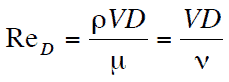
It is defined as:
where:
V is the flow velocity,
D is a characteristic linear dimension, (travelled length of the fluid; hydraulic diameter etc.)
ρ fluid density (kg/m3),
μ dynamic viscosity (Pa.s),
ν kinematic viscosity (m2/s); ν = μ / ρ.
Example: Moody Diagram
Determine the friction factor (fD) for fluid flow in a pipe of 700mm in diameter that has the Reynolds number of 50 000 000 and an absolute roughness of 0.035 mm.
Solution:
The relative roughness is equal to ε = 0.035 / 700 = 5 x 10⁻⁵. Using the Moody Chart, a Reynolds number of 50 000 000 intersects the curve corresponding to a relative roughness of 5 x 10⁻⁵ at a friction factor of 0.011.
Example: Moody chart. Source: Donebythesecondlaw at the English language Wikipedia, CC BY-SA 3.0, https://commons.wikimedia.org/w/index.php?curid=4681366
Darcy Friction Factor for various flow regime
The most common classification of flow regimes is according to the Reynolds number. The Reynolds number is a dimensionless number comprised of the physical characteristics of the flow and it determines whether the flow is laminar or turbulent. An increasing Reynolds number indicates an increasing turbulence of flow. As can be seen from the Moody chart, also Darcy friction factor is highly dependent on the flow regime (i.e. on the Reynolds number).
Darcy Friction Factor for Laminar Flow
For practical purposes, if theReynolds number is less than 2000, the flow is laminar. The accepted transition Reynolds number for flow in a circular pipe is Red,crit = 2300. For laminar flow, the head loss is proportional to velocity rather than velocity squared, thus the friction factor is inversely proportional to velocity.
The Darcy friction factor for laminar (slow) flows is a consequence of Poiseuille’s law that and it is given by following equations:
Darcy Friction Factor for Transitional Flow
At Reynolds numbers between about 2000 and 4000 the flow is unstable as a result of the onset of turbulence. These flows are sometimes referred to as transitional flows. The Darcy friction factor contains large uncertainties in this flow regime and is not well understood.
Darcy Friction Factor for Turbulent Flow
If the Reynolds number is greater than 3500, the flow is turbulent. Most fluid systems in nuclear facilities operate with turbulent flow. In this flow regime the resistance to flow follows the Darcy–Weisbach equation: it is proportional to the square of the mean flow velocity. The Darcy friction factor depends strongly on the relative roughness of the pipe’s inner surface.
The most common method to determine a friction factor for turbulent flow is to use the Moody chart. The Moody chart (also known as the Moody diagram) is a log-log plot of the Colebrook correlation that relates the Darcy friction factor, Reynolds number, and the relative roughness for fully developed flow in a circular pipe. The Colebrook–White equation:
which is also known as the Colebrook equation, expresses the Darcy friction factor fas a function of pipe relative roughnessε / Dh and Reynolds number.
In 1939, Colebrook found an implicit correlation for the friction factor in round pipes by fitting the data of experimental studies of turbulent flow in smooth and rough pipes.
For hydraulically smooth pipe and the turbulent flow (Re < 105) the friction factor can be approximated by Blasius formula:
f = (100.Re)-¼
It must be noted, at very large Reynolds numbers, the friction factor is independent of the Reynolds number. This is because the thickness of laminar sublayer (viscous sublayer) decreases with increasing Reynolds number. For very large Reynolds numbers the thickness of laminar sublayer is comparable to the surface roughness and it directly influences the flow. The laminar sublayer becomes so thin that the surface roughness protrudes into the flow. The frictional losses in this case are produced in the main flow primarily by the protruding roughness elements, and the contribution of the laminar sublayer is negligible.
References:
Reactor Physics and Thermal Hydraulics:
J. R. Lamarsh, Introduction to Nuclear Reactor Theory, 2nd ed., Addison-Wesley, Reading, MA (1983).
J. R. Lamarsh, A. J. Baratta, Introduction to Nuclear Engineering, 3d ed., Prentice-Hall, 2001, ISBN: 0-201-82498-1.
W. M. Stacey, Nuclear Reactor Physics, John Wiley & Sons, 2001, ISBN: 0- 471-39127-1.
Todreas Neil E., Kazimi Mujid S. Nuclear Systems Volume I: Thermal Hydraulic Fundamentals, Second Edition. CRC Press; 2 edition, 2012, ISBN: 978-0415802871
Zohuri B., McDaniel P. Thermodynamics in Nuclear Power Plant Systems. Springer; 2015, ISBN: 978-3-319-13419-2
Moran Michal J., Shapiro Howard N. Fundamentals of Engineering Thermodynamics, Fifth Edition, John Wiley & Sons, 2006, ISBN: 978-0-470-03037-0
Kleinstreuer C. Modern Fluid Dynamics. Springer, 2010, ISBN 978-1-4020-8670-0.
U.S. Department of Energy, THERMODYNAMICS, HEAT TRANSFER, AND FLUID FLOW. DOE Fundamentals Handbook, Volume 1, 2 and 3. June 1992.
White Frank M., Fluid Mechanics, McGraw-Hill Education, 7th edition, February, 2010, ISBN: 978-0077422417
See also:
Major Loss
We hope, this article, Moody Diagram, helps you. If so, give us a like in the sidebar. Main purpose of this website is to help the public to learn some interesting and important information about thermal engineering.
The Darcy friction factor for laminar (slow) flows is a consequence of Poiseuille’s law that and it is given by following equations: f = 64/Re
Darcy Friction Factor for Laminar Flow
For practical purposes, if theReynolds number is less than 2000, the flow is laminar. The accepted transition Reynolds number for flow in a circular pipe is Red,crit = 2300. For laminar flow, the head loss is proportional to velocity rather than velocity squared, thus the friction factor is inversely proportional to velocity.
The Darcy friction factor for laminar (slow) flows is a consequence of Poiseuille’s law that and it is given by following equations:
Laminar flow:
Re < 2000
‘low’ velocity
Fluid particles move in straight lines
Layers of water flow over one another at different speeds with virtually no mixing between layers.
The flow velocity profile for laminar flow in circular pipes is parabolic in shape, with a maximum flow in the center of the pipe and a minimum flow at the pipe walls.
The average flow velocity is approximately one half of the maximum velocity.
Simple mathematical analysis is possible.
Rare in practice in water systems.
Source: Donebythesecondlaw at the English language Wikipedia, CC BY-SA 3.0, https://commons.wikimedia.org/w/index.php?curid=4681366
References:
Reactor Physics and Thermal Hydraulics:
J. R. Lamarsh, Introduction to Nuclear Reactor Theory, 2nd ed., Addison-Wesley, Reading, MA (1983).
J. R. Lamarsh, A. J. Baratta, Introduction to Nuclear Engineering, 3d ed., Prentice-Hall, 2001, ISBN: 0-201-82498-1.
W. M. Stacey, Nuclear Reactor Physics, John Wiley & Sons, 2001, ISBN: 0- 471-39127-1.
Todreas Neil E., Kazimi Mujid S. Nuclear Systems Volume I: Thermal Hydraulic Fundamentals, Second Edition. CRC Press; 2 edition, 2012, ISBN: 978-0415802871
Zohuri B., McDaniel P. Thermodynamics in Nuclear Power Plant Systems. Springer; 2015, ISBN: 978-3-319-13419-2
Moran Michal J., Shapiro Howard N. Fundamentals of Engineering Thermodynamics, Fifth Edition, John Wiley & Sons, 2006, ISBN: 978-0-470-03037-0
Kleinstreuer C. Modern Fluid Dynamics. Springer, 2010, ISBN 978-1-4020-8670-0.
U.S. Department of Energy, THERMODYNAMICS, HEAT TRANSFER, AND FLUID FLOW. DOE Fundamentals Handbook, Volume 1, 2 and 3. June 1992.
White Frank M., Fluid Mechanics, McGraw-Hill Education, 7th edition, February, 2010, ISBN: 978-0077422417
See also:
Major Loss
We hope, this article, Friction Factor for Laminar Flow, helps you. If so, give us a like in the sidebar. Main purpose of this website is to help the public to learn some interesting and important information about thermal engineering.
The Darcy friction factor contains large uncertainties in this flow regime and is not well understood. Friction Factor for Transitional Flow
Flow Regimes
Laminar flow. For practical purposes, if the Reynolds number is less than 2000, the flow is laminar. The accepted transition Reynolds number for flow in a circular pipe is Red,crit = 2300.
Transitional flow. At Reynolds numbers between about 2000 and 4000 the flow is unstable as a result of the onset of turbulence. These flows are sometimes referred to as transitional flows.
Turbulent flow. If the Reynolds number is greater than 3500, the flow is turbulent. Most fluid systems in nuclear facilities operate with turbulent flow.
Darcy Friction Factor for Transitional Flow
At Reynolds numbers between about 2000 and 4000 the flow is unstable as a result of the onset of turbulence. These flows are sometimes referred to as transitional flows. The Darcy friction factor contains large uncertainties in this flow regime and is not well understood.
Source: Donebythesecondlaw at the English language Wikipedia, CC BY-SA 3.0, https://commons.wikimedia.org/w/index.php?curid=4681366
References:
Reactor Physics and Thermal Hydraulics:
J. R. Lamarsh, Introduction to Nuclear Reactor Theory, 2nd ed., Addison-Wesley, Reading, MA (1983).
J. R. Lamarsh, A. J. Baratta, Introduction to Nuclear Engineering, 3d ed., Prentice-Hall, 2001, ISBN: 0-201-82498-1.
W. M. Stacey, Nuclear Reactor Physics, John Wiley & Sons, 2001, ISBN: 0- 471-39127-1.
Todreas Neil E., Kazimi Mujid S. Nuclear Systems Volume I: Thermal Hydraulic Fundamentals, Second Edition. CRC Press; 2 edition, 2012, ISBN: 978-0415802871
Zohuri B., McDaniel P. Thermodynamics in Nuclear Power Plant Systems. Springer; 2015, ISBN: 978-3-319-13419-2
Moran Michal J., Shapiro Howard N. Fundamentals of Engineering Thermodynamics, Fifth Edition, John Wiley & Sons, 2006, ISBN: 978-0-470-03037-0
Kleinstreuer C. Modern Fluid Dynamics. Springer, 2010, ISBN 978-1-4020-8670-0.
U.S. Department of Energy, THERMODYNAMICS, HEAT TRANSFER, AND FLUID FLOW. DOE Fundamentals Handbook, Volume 1, 2 and 3. June 1992.
White Frank M., Fluid Mechanics, McGraw-Hill Education, 7th edition, February, 2010, ISBN: 978-0077422417
See also:
Major Loss
We hope, this article, Friction Factor for Transitional Flow, helps you. If so, give us a like in the sidebar. Main purpose of this website is to help the public to learn some interesting and important information about thermal engineering.
The Darcy friction factor for turbulent flow can be determined by Colebrook–White equation, that relates the Darcy friction factor, Reynolds number, and the relative roughness. Thermal Engineering
Darcy Friction Factor for Turbulent Flow
If the Reynolds number is greater than 3500, the flow is turbulent. Most fluid systems in nuclear facilities operate with turbulent flow. In this flow regime the resistance to flow follows the Darcy–Weisbach equation: it is proportional to the square of the mean flow velocity. The Darcy friction factor depends strongly on the relative roughness of the pipe’s inner surface.
The most common method to determine a friction factor for turbulent flow is to use the Moody diagram. The Moody diagram (also known as the Moody chart) is a log-log plot of the Colebrook correlation that relates the Darcy friction factor, Reynolds number, and the relative roughness for fully developed flow in a circular pipe. The Colebrook–White equation:
Turbulent Flow:
Re > 4000
‘high’ velocity
The flow is characterized by the irregular movement of particles of the fluid.
Average motion is in the direction of the flow
The flow velocity profile for turbulent flow is fairly flat across the center section of a pipe and drops rapidly extremely close to the walls.
The average flow velocity is approximately equal to the velocity at the center of the pipe.
Mathematical analysis is very difficult.
Most common type of flow.
which is also known as the Colebrook equation, expresses the Darcy friction factor fas a function of pipe relative roughnessε / Dh and Reynolds number.
In 1939, Colebrook found an implicit correlation for the friction factor in round pipes by fitting the data of experimental studies of turbulent flow in smooth and rough pipes.
For hydraulically smooth pipe and the turbulent flow (Re < 105) the friction factor can be approximated by Blasius formula:
f = (100.Re)-¼
It must be noted, at very large Reynolds numbers, the friction factor is independent of the Reynolds number. This is because the thickness of laminar sublayer (viscous sublayer) decreases with increasing Reynolds number. For very large Reynolds numbers the thickness of laminar sublayer is comparable to the surface roughness and it directly influences the flow. The laminar sublayer becomes so thin that the surface roughness protrudes into the flow. The frictional losses in this case are produced in the main flow primarily by the protruding roughness elements, and the contribution of the laminar sublayer is negligible.
Source: Donebythesecondlaw at the English language Wikipedia, CC BY-SA 3.0, https://commons.wikimedia.org/w/index.php?curid=4681366
References:
Reactor Physics and Thermal Hydraulics:
J. R. Lamarsh, Introduction to Nuclear Reactor Theory, 2nd ed., Addison-Wesley, Reading, MA (1983).
J. R. Lamarsh, A. J. Baratta, Introduction to Nuclear Engineering, 3d ed., Prentice-Hall, 2001, ISBN: 0-201-82498-1.
W. M. Stacey, Nuclear Reactor Physics, John Wiley & Sons, 2001, ISBN: 0- 471-39127-1.
Todreas Neil E., Kazimi Mujid S. Nuclear Systems Volume I: Thermal Hydraulic Fundamentals, Second Edition. CRC Press; 2 edition, 2012, ISBN: 978-0415802871
Zohuri B., McDaniel P. Thermodynamics in Nuclear Power Plant Systems. Springer; 2015, ISBN: 978-3-319-13419-2
Moran Michal J., Shapiro Howard N. Fundamentals of Engineering Thermodynamics, Fifth Edition, John Wiley & Sons, 2006, ISBN: 978-0-470-03037-0
Kleinstreuer C. Modern Fluid Dynamics. Springer, 2010, ISBN 978-1-4020-8670-0.
U.S. Department of Energy, THERMODYNAMICS, HEAT TRANSFER, AND FLUID FLOW. DOE Fundamentals Handbook, Volume 1, 2 and 3. June 1992.
White Frank M., Fluid Mechanics, McGraw-Hill Education, 7th edition, February, 2010, ISBN: 978-0077422417
See also:
Major Loss
We hope, this article, Friction Factor for Turbulent Flow – Colebrook Equation, helps you. If so, give us a like in the sidebar. Main purpose of this website is to help the public to learn some interesting and important information about thermal engineering.
Minor head loss are local pressure losses or pressure drops of various hydraulic elements such as bends, fittings, valves, elbows, tees or heated channels. Thermal Engineering
The Hydraulic Head
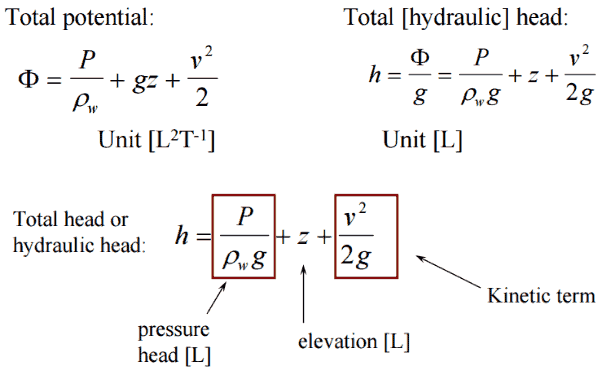
In general,the hydraulic head, or total head, is a measure of the potential of fluid at the measurement point. It can be used to determine a hydraulic gradient between two or more points.
In fluid dynamics, head is a concept that relates the energy in an incompressible fluid to the height of an equivalent static column of that fluid. The units for all the different forms of energy in the Bernoulli’s equation can be measured also in units of distance, and therefore these terms are sometimes referred to as “heads” (pressure head, velocity head, and elevation head). Head is also defined for pumps. This head is usually referred to as the static head and represents the maximum height (pressure) it can deliver. Therefore the characteristics of all pumps can be usually read from its Q-H curve (flow rate – height).
There are four types of potential (head):
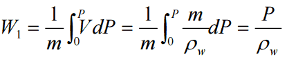
Pressure potential – Pressure head: The pressure head represents the flow energy of a column of fluid whose weight is equivalent to the pressure of the fluid.ρw: density of water assumed to be independent of pressure
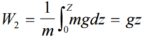
Elevation potential – Elevation head: The elevation head represents the potential energy of a fluid due to its elevation above a reference level.
Kinetic potential – Kinetic head: The kinetic head represents the kinetic energy of the fluid. It is the height in feet that a flowing fluid would rise in a column if all of its kinetic energy were converted to potential energy.
The sum of the elevation head, kinetic head, and pressure head of a fluid is called the total head. Thus, Bernoulli’s equation states that the total head of the fluid is constant.
Consider a pipe containing an ideal fluid. If this pipe undergoes a gradual expansion in diameter, the continuity equation tells us that as the pipe diameter increases, the flow velocity must decrease in order to maintain the same mass flow rate. Since the outlet velocity is less than the inlet velocity, the kinetic head of the flow must decrease from the inlet to the outlet. If there is no change in elevation head (the pipe lies horizontal), the decrease in kinetic head must be compensated for by an increase in pressure head.
Classification of Head Loss
The head loss of a pipe, tube or duct system, is the same as that produced in a straight pipe or duct whose length is equal to the pipes of the original systems plus the sum of the equivalent lengths of all the components in the system.
As can be seen, the head loss of piping system is divided into two main categories, “major losses” associated with energy loss per length of pipe, and “minor losses” associated with bends, fittings, valves, etc.
Major Head Loss – due to friction in pipes and ducts.
Minor Head Loss – due to components as valves, fittings, bends and tees.
The head loss can be then expressed as:
hloss = Σ hmajor_losses + Σ hminor_losses
Minor Head Loss – Local Losses
In industry any pipe system contains different technological elements as bends, fittings, valves or heated channels. These additional components add to the overall head loss of the system. Such losses are generally termed minor losses, although they often account for a major portion of the head loss. For relatively short pipe systems, with a relatively large number of bends and fittings, minor losses can easily exceed major losses (especially with a partially closed valve that can cause a greater pressure loss than a long pipe, in fact when a valve is closed or nearly closed, the minor loss is infinite).
The minor losses are commonly measured experimentally. The data, especially for valves, are somewhat dependent upon the particular manufacturer’s design.
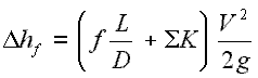
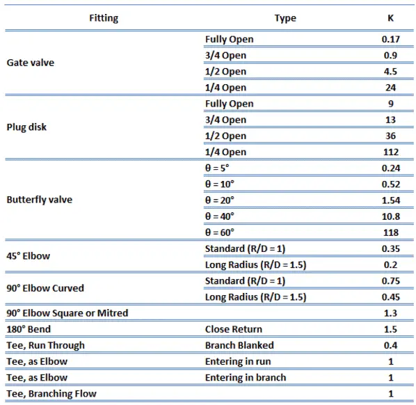
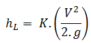
Like pipe friction, the minor losses are roughly proportional to the square of the flow rate and therefore they can be easy integrated into the Darcy-Weisbach equation. K is the sum of all of the loss coefficients in the length of pipe, each contributing to the overall head loss.
There are several methods how to calculate head loss from fittings, bends and elbows. In the following section these methods are summarized in the order from the simplest to the most sophisticated.
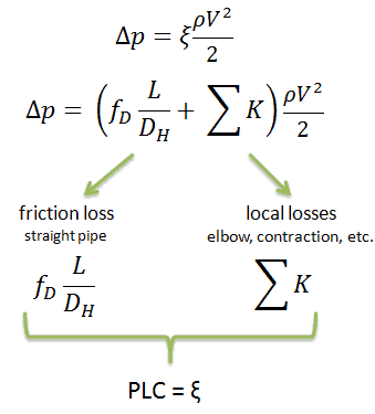
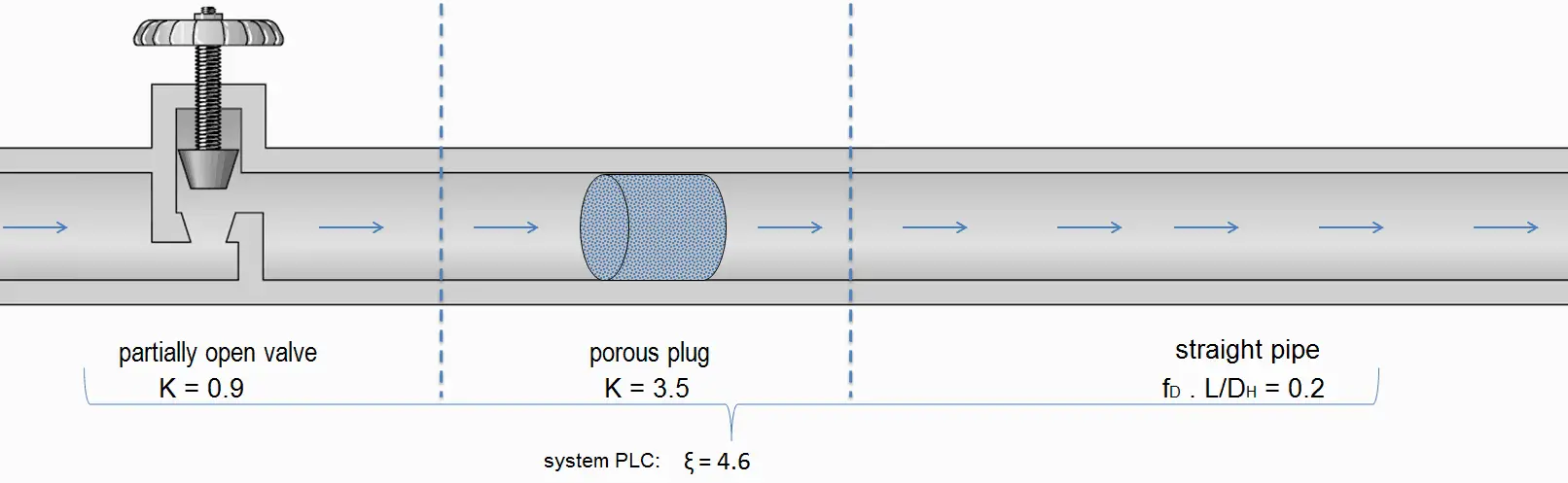
Pressure Loss Coefficient - PLC
Sometimes, engineers use the pressure loss coefficient, PLC. It is noted K or ξ (pronounced “xi”). This coefficient characterizes pressure loss of a certain hydraulic system or of a part of a hydraulic system. It can be easily measured in hydraulic loops. The pressure loss coefficient can be defined or measured for both straight pipes and especially for local (minor) losses.
Equivalent Length Method
The equivalent length method (The Le/D method) allows the user to describe the pressure loss through an elbow or a fitting as a length of straight pipe.
This method is based on the observation that the major losses are also proportional to the velocity head (v2/2g).
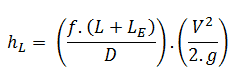
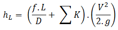
The Le/D method simply increases the multiplying factor in the Darcy-Weisbach equation (i.e.ƒ.L/D) by a length of straight pipe (i.e. Le) which would give rise to a pressure loss equivalent to the losses in the fittings, hence the name “equivalent length”. The multiplying factor therefore becomes ƒ(L+Le)/D and the equation for calculation of pressure loss of the system is therefore:
[/lgc_column]
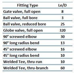
All fittings, elbows, tees, can be summed up to make one total length, and the pressure loss calculated from this length. It has been found experimentally that if the equivalent lengths for a range of sizes of a given type of fitting are divided by the diameters of the fittings then an almost constant ratio (i.e. Le/D) is obtained. The advantage of the equivalent length method is that a single data value is sufficient to cover all sizes of that fitting and therefore the tabulation of equivalent length data is relatively easy. Some typical equivalent lengths are shown in the table.
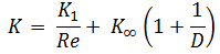
Resistance Coefficient Method – K Method – Excess head
The resistance coefficient method (or K-method, or Excess head method) allows the user to describe the pressure loss through an elbow or a fitting by a dimensionless number – K. This dimensionless number (K) can be incorporated into the Darcy-Weisbach equation in a very similar way to the equivalent length method. Instead of of equivalent length data in this case the dimensionless number (K) is used to characterise the fitting without linking it to the properties of the pipe.
The K-value represents the multiple of velocity heads that will be lost by fluid passing through the fitting. The equation for calculation of pressure loss of the hydraulic element is therefore: Therefore the equation for calculation of pressure loss of entire hydraulic system is:
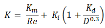
The K-value can be characterised for various flow regime (i.e. according to the Reynolds number) and this causes it is more accurate than the equivalent length method.
There are several other methods for calculating pressure loss for fittings, these methods are more sophisticated and also more accurate:
2K-Method. The 2K method is a technique developed by Hooper B.W. to predict the head loss in an elbow, valve or tee. The 2K method improves on the excess head method by characterising the change in pressure loss due to varying Reynolds number. The 2-K method is advantageous over other method especially in the laminar flow region.
3K-Method. The 3K method (by Ron Darby in 1999) further improves the accuracy of the pressure loss calculation by also characterising the change in geometric proportions of a fitting as its size changes. This makes the 3K method particularly accurate for a system with large fittings.
Summary:
Head loss of hydraulic system is divided into two main categories:
Minor Head Loss – due to components as valves, bends…
A special form of Darcy’s equation can be used to calculate minor losses.
The minor losses are roughly proportional to the square of the flow rate and therefore they can be easy integrated into the Darcy-Weisbach equation through resistance coefficient K.
As a local pressure loss fluid acceleration in a heated channel can be also considered.
There are following methods:
Equivalent length method
K-method (resistance coeff. method)
2K-method
3K-method
Why the head loss is very important?
As can be seen from the picture, the head loss is forms key characteristic of any hydraulic system. In systems, in which some certain flowrate must be maintained (e.g. to provide sufficient cooling or heat transfer from a reactor core), the equilibrium of the head loss and the head added by a pump determines the flowrate through the system.
Q-H characteristic diagram of centrifugal pump and of pipeline
Flow through Elbow – Minor Loss
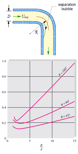
The flow through elbows is quite complicated. In fact, any curved pipe always induces a larger loss than the simple straight pipe. This is due to the fact in a curved pipe the flow separates on the curved walls. For very small radius of curvature the incoming flow is even unable to make the turn at the bend, therefore the flow separates and in part stagnates against the opposite side of the pipe. In this part of the bend the pressure raises (as a result of the Bernoulli’s principle) and the velocity decreases.
An interesting feature of the K-values for elbows is their non-monotone behavior as R/D ratio increases. The K-values include both the local losses and frictional losses of the pipe. The local losses, caused by flow separation and secondary flow, decrease with R/D, while the frictional losses increase because the bend length increases. Therefore there is a minimum in the K-value near the normalized radius of curvature of 3.
Fluid Acceleration
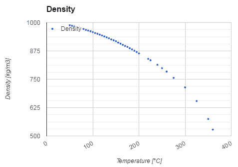
Density of liquid (compressed) water as a function of temperature of water
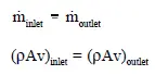
It is known that when the fluid is heated (e.g. in a fuel channel), the fluid expands (change in the fluid density) and increases its flow velocity as a result of the continuity equation (the channel cross-section remains the same). For a control volume that has a single inlet and a single outlet, this equation states that, for steady-state flow, the mass flow rate into the volume must equal the mass flow rate out.
Mass entering per unit time = Mass leaving per unit time
Another very important principle states (Bernoulli’s principle) that the increase in flow velocity in the heated channel causes the lowering of fluid pressure. This pressure loss can be also considered as a local pressure loss and can be calculated from the following equation:
Flow rate through a reactor core – coolant acceleration
It is an illustrative example, following data do not correspond to any reactor design.
Example of flow rates in a reactor. It is an illustrative example, data do not represent any reactor design.
Pressurized water reactors are cooled and moderated by high-pressure liquid water (e.g. 16MPa). At this pressure water boils at approximately 350°C (662°F). Inlet temperature of the water is about 290°C (⍴ ~ 720 kg/m3). The water (coolant) is heated in the reactor core to approximately 325°C (⍴ ~ 654 kg/m3) as the water flows through the core.
The primary circuit of typical PWRs is divided into 4 independent loops (piping diameter ~ 700mm), each loop comprises a steam generator and one main coolant pump. Inside the reactor pressure vessel (RPV), the coolant first flows down outside the reactor core (through the downcomer). From the bottom of the pressure vessel, the flow is reversed up through the core, where the coolant temperature increases as it passes through the fuel rods and the assemblies formed by them.
Calculate:
Pressure loss due to the coolant acceleration in an isolated fuel channel
when
channel inlet flow velocity is equal to 5.17 m/s
channel outlet flow velocity is equal to 5.69 m/s
Solution:
The pressure loss due to the coolant acceleration in an isolated fuel channel is then:
This fact has important consequences. Due to the different relative power of fuel assemblies in a core, these fuel assemblies have different hydraulic resistance and this may induce local lateral flow of primary coolant and it must be considered in thermal-hydraulic calculations.
References:
Reactor Physics and Thermal Hydraulics:
J. R. Lamarsh, Introduction to Nuclear Reactor Theory, 2nd ed., Addison-Wesley, Reading, MA (1983).
J. R. Lamarsh, A. J. Baratta, Introduction to Nuclear Engineering, 3d ed., Prentice-Hall, 2001, ISBN: 0-201-82498-1.
W. M. Stacey, Nuclear Reactor Physics, John Wiley & Sons, 2001, ISBN: 0- 471-39127-1.
Todreas Neil E., Kazimi Mujid S. Nuclear Systems Volume I: Thermal Hydraulic Fundamentals, Second Edition. CRC Press; 2 edition, 2012, ISBN: 978-0415802871
Zohuri B., McDaniel P. Thermodynamics in Nuclear Power Plant Systems. Springer; 2015, ISBN: 978-3-319-13419-2
Moran Michal J., Shapiro Howard N. Fundamentals of Engineering Thermodynamics, Fifth Edition, John Wiley & Sons, 2006, ISBN: 978-0-470-03037-0
Kleinstreuer C. Modern Fluid Dynamics. Springer, 2010, ISBN 978-1-4020-8670-0.
U.S. Department of Energy, THERMODYNAMICS, HEAT TRANSFER, AND FLUID FLOW. DOE Fundamentals Handbook, Volume 1, 2 and 3. June 1992.
White Frank M., Fluid Mechanics, McGraw-Hill Education, 7th edition, February, 2010, ISBN: 978-0077422417
See also:
Fluid Dynamics
We hope, this article, Minor Head Loss – Local Losses, helps you. If so, give us a like in the sidebar. Main purpose of this website is to help the public to learn some interesting and important information about thermal engineering.
The equivalent length method (The Le/D method) allows the user to describe the pressure loss through an elbow or a fitting as a length of straight pipe. Thermal Engineering
Equivalent Length Method
The equivalent length method (The Le/D method) allows the user to describe the pressure loss through an elbow or a fitting as a length of straight pipe.
This method is based on the observation that the major losses are also proportional to the velocity head (v2/2g).
The Le/D method simply increases the multiplying factor in the Darcy-Weisbach equation (i.e.ƒ.L/D) by a length of straight pipe (i.e. Le) which would give rise to a pressure loss equivalent to the losses in the fittings, hence the name “equivalent length”. The multiplying factor therefore becomes ƒ(L+Le)/D and the equation for calculation of pressure loss of the system is therefore:
All fittings, elbows, tees, can be summed up to make one total length, and the pressure loss calculated from this length. It has been found experimentally that if the equivalent lengths for a range of sizes of a given type of fitting are divided by the diameters of the fittings then an almost constant ratio (i.e. Le/D) is obtained. The advantage of the equivalent length method is that a single data value is sufficient to cover all sizes of that fitting and therefore the tabulation of equivalent length data is relatively easy. Some typical equivalent lengths are shown in the table.
A special form of Darcy’s equation can be used to calculate minor losses.
The minor losses are roughly proportional to the square of the flow rate and therefore they can be easy integrated into the Darcy-Weisbach equation through resistance coefficient K.
As a local pressure loss fluid acceleration in a heated channel can be also considered.
There are following methods:
Equivalent length method
K-method (resistance coeff. method)
2K-method
3K-method
Why the head loss is very important?
As can be seen from the picture, the head loss is forms key characteristic of any hydraulic system. In systems, in which some certain flowrate must be maintained (e.g. to provide sufficient cooling or heat transfer from a reactor core), the equilibrium of the head loss and the head added by a pump determines the flowrate through the system.
Q-H characteristic diagram of centrifugal pump and of pipeline
References:
Reactor Physics and Thermal Hydraulics:
J. R. Lamarsh, Introduction to Nuclear Reactor Theory, 2nd ed., Addison-Wesley, Reading, MA (1983).
J. R. Lamarsh, A. J. Baratta, Introduction to Nuclear Engineering, 3d ed., Prentice-Hall, 2001, ISBN: 0-201-82498-1.
W. M. Stacey, Nuclear Reactor Physics, John Wiley & Sons, 2001, ISBN: 0- 471-39127-1.
Todreas Neil E., Kazimi Mujid S. Nuclear Systems Volume I: Thermal Hydraulic Fundamentals, Second Edition. CRC Press; 2 edition, 2012, ISBN: 978-0415802871
Zohuri B., McDaniel P. Thermodynamics in Nuclear Power Plant Systems. Springer; 2015, ISBN: 978-3-319-13419-2
Moran Michal J., Shapiro Howard N. Fundamentals of Engineering Thermodynamics, Fifth Edition, John Wiley & Sons, 2006, ISBN: 978-0-470-03037-0
Kleinstreuer C. Modern Fluid Dynamics. Springer, 2010, ISBN 978-1-4020-8670-0.
U.S. Department of Energy, THERMODYNAMICS, HEAT TRANSFER, AND FLUID FLOW. DOE Fundamentals Handbook, Volume 1, 2 and 3. June 1992.
White Frank M., Fluid Mechanics, McGraw-Hill Education, 7th edition, February, 2010, ISBN: 978-0077422417
See also:
Minor Loss
We hope, this article, Equivalent Pipe Length Method, helps you. If so, give us a like in the sidebar. Main purpose of this website is to help the public to learn some interesting and important information about thermal engineering.