Facebook Instagram Youtube Twitter

What is Streamline Flow – Definition

The term streamline flow is descriptive of the laminar flow. Fluid particles move in definite and observable paths or streamlines. Streamline flow. Thermal Engineering

Streamline Flow

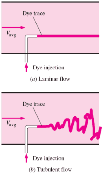
The term streamline flow is descriptive of the laminar flow because, in laminar flow, layers of water flowing over one another at different speeds with virtually no mixing between layers, fluid particles move in definite and observable paths or streamlines.

In fluid dynamics, laminar flow is characterized by smooth or in regular paths of particles of the fluid, in contrast to turbulent flow, that is characterized by the irregular movement of particles of the fluid. The fluid flows in parallel layers (with minimal lateral mixing), with no disruption between the layers. Therefore the laminar flow is also referred to as streamline or viscous flow.

When a fluid is flowing through a closed channel such as a pipe or between two flat plates, either of two types of flow (laminar flow or turbulent flow) may occur depending on the velocity, viscosity of the fluid and the size of the pipe. Laminar flow tends to occur at lower velocities and high viscosity. On the other hand turbulent flow tends to occur at higher velocities and low viscosity.

Since laminar flow is common only in cases in which the flow channel is relatively small, the fluid is moving slowly, and its viscosity is relatively high, laminar flow is not common in industrial processes. Most industrial flows, especially those in nuclear engineering are turbulent. Nevertheless laminar flow occurs at any Reynolds number near solid boundaries in a thin layer just adjacent to the surface, this layer is usually referred to as the laminar sublayer and it is very important in heat transfer.

Despite the small thickness of the laminar sublayer (usually much less than 1 percent of the pipe diameter), since it strongly influences the flow in the rest of the pipe. Any irregularity or roughness on the surface disturbs this layer and significantly affects the flow. Therefore, unlike laminar flow, the friction factor in turbulent flow is a strong function of surface roughness. 
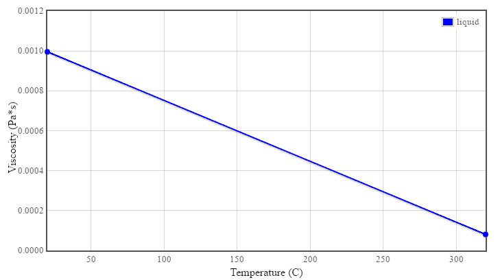
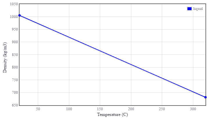
Charts: Viscosity and Density of Water (16MPa)
Viscosity of Water - 16MPa
Density of Water - 16 MPa

Laminar vs. Turbulent Flow

Laminar vs. Turbulent Flow

Laminar Flow:

  • Re < 2000
  • ‘low’ velocity
  • Fluid particles move in straight lines
  • Layers of water flow over one another at different speeds with virtually no mixing between layers.
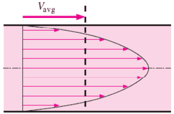
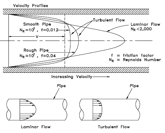
  • The flow velocity profile for laminar flow in circular pipes is parabolic in shape, with a maximum flow in the center of the pipe and a minimum flow at the pipe walls.
  • The average flow velocity is approximately one half of the maximum velocity.
  • Simple mathematical analysis is possible.
  • Rare in practice in water systems.

Turbulent Flow:

  • Re > 4000
  • ‘high’ velocity
  • The flow is characterized by the irregular movement of particles of the fluid.
  • Average motion is in the direction of the flow
  • The flow velocity profile for turbulent flow is fairly flat across the center section of a pipe and drops rapidly extremely close to the walls.
  • The average flow velocity is approximately equal to the velocity at the center of the pipe.
  • Mathematical analysis is very difficult.
  • Most common type of flow.
Average velocity Vavg is defined as the average speed through a cross section. For fully developed laminar pipe flow, Vavg is half of the maximum velocity.
 
References:
Reactor Physics and Thermal Hydraulics:
  1. J. R. Lamarsh, Introduction to Nuclear Reactor Theory, 2nd ed., Addison-Wesley, Reading, MA (1983).
  2. J. R. Lamarsh, A. J. Baratta, Introduction to Nuclear Engineering, 3d ed., Prentice-Hall, 2001, ISBN: 0-201-82498-1.
  3. W. M. Stacey, Nuclear Reactor Physics, John Wiley & Sons, 2001, ISBN: 0- 471-39127-1.
  4. Glasstone, Sesonske. Nuclear Reactor Engineering: Reactor Systems Engineering, Springer; 4th edition, 1994, ISBN: 978-0412985317
  5. Todreas Neil E., Kazimi Mujid S. Nuclear Systems Volume I: Thermal Hydraulic Fundamentals, Second Edition. CRC Press; 2 edition, 2012, ISBN: 978-0415802871
  6. Zohuri B., McDaniel P. Thermodynamics in Nuclear Power Plant Systems. Springer; 2015, ISBN: 978-3-319-13419-2
  7. Moran Michal J., Shapiro Howard N. Fundamentals of Engineering Thermodynamics, Fifth Edition, John Wiley & Sons, 2006, ISBN: 978-0-470-03037-0
  8. Kleinstreuer C. Modern Fluid Dynamics. Springer, 2010, ISBN 978-1-4020-8670-0.
  9. U.S. Department of Energy, THERMODYNAMICS, HEAT TRANSFER, AND FLUID FLOW. DOE Fundamentals Handbook, Volume 1, 2 and 3. June 1992.
  10. White Frank M., Fluid Mechanics, McGraw-Hill Education, 7th edition, February, 2010, ISBN: 978-0077422417

See also:

Laminar Flow

We hope, this article, Streamline Flow, helps you. If so, give us a like in the sidebar. Main purpose of this website is to help the public to learn some interesting and important information about thermal engineering.
What is Turbulent Flow – Definition

Turbulent flow is characterized by the irregular movement of particles (one can say chaotic) of the fluid. Turbulent flow tends to occur at higher velocities, low viscosity. Thermal Engineering

Turbulent Flow

In fluid dynamics, turbulent flow is characterized by the irregular movement of particles (one can say chaotic) of the fluid. In contrast to laminar flow the fluid does not flow in parallel layers, the lateral mixing is very high, and there is a disruption between the layers. Turbulence is also characterized by recirculation, eddies, and apparent randomness. In turbulent flow the speed of the fluid at a point is continuously undergoing changes in both magnitude and direction.

Detailed knowledge of behaviour of turbulent flow regime is of importance in engineering, because most industrial flows, especially those in nuclear engineering are turbulent. Unfortunately, the highly intermittent and irregular character of turbulence complicates all analyses. In fact, turbulence is often said to be the “last unsolved problem in classical mathemetical physics.”

The main tool available for their analysis is CFD analysis. CFD is a branch of fluid mechanics that uses numerical analysis and algorithms to solve and analyze problems that involve turbulent fluid flows. It is widely accepted that the Navier–Stokes equations (or simplified Reynolds-averaged Navier–Stokes equations) are capable of exhibiting turbulent solutions, and these equations are the basis for essentially all CFD codes.

See also: Internal Flow

See also: External Flow

Characteristics of Turbulent Flow

  • Turbulent flow tends to occur at higher velocities, low viscosity and at higher characteristic linear dimensions.
  • If the Reynolds number is greater than Re > 3500, the flow is turbulent.
  • Irregularity: The flow is characterized by the irregular movement of particles of the fluid. The movement of fluid particles is chaotic. For this reason, turbulent flow is normally treated statistically rather than deterministically.
  • Diffusivity: In turbulent flow, a fairly flat velocity distribution exists across the section of pipe, with the result that the entire fluid flows at a given single value and drops rapidly extremely close to the walls. The characteristic which is responsible for the enhanced mixing and increased rates of mass, momentum and energy transports in a flow is called “diffusivity”.
  • Rotationality: Turbulent flow is characterized by a strong three-dimensional vortex generation mechanism. This mechanism is known as vortex stretching.
  • Dissipation: A dissipative process is a process in which the kinetic energy of turbulent flow is transformed into internal energy by viscous shear stress.

Reynolds Number

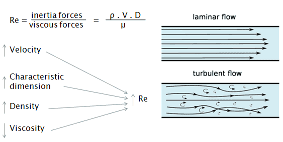
The Reynolds number is the ratio of inertial forces to viscous forces and is a convenient parameter for predicting if a flow condition will be laminar or turbulent. It can be interpreted that when the viscous forces are dominant (slow flow, low Re) they are sufficient enough to keep all the fluid particles in line, then the flow is laminar. Even very low Re indicates viscous creeping motion, where inertia effects are negligible. When the inertial forces dominate over the viscous forces (when the fluid is flowing faster and Re is larger) then the flow is turbulent.

reynolds number

It is a dimensionless number comprised of the physical characteristics of the flow. An increasing Reynolds number indicates an increasing turbulence of flow.

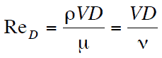
It is defined as:
Reynolds number

where:
V is the flow velocity,
D is a characteristic linear dimension, (travelled length of the fluid; hydraulic diameter etc.)
ρ fluid density (kg/m3),
μ dynamic viscosity (Pa.s),
ν kinematic viscosity (m2/s);  ν = μ / ρ.

Laminar vs. Turbulent Flow

Laminar vs. Turbulent Flow

Laminar flow:

  • Re < 2000
  • ‘low’ velocity
  • Fluid particles move in straight lines
  • Layers of water flow over one another at different speeds with virtually no mixing between layers.
  • The flow velocity profile for laminar flow in circular pipes is parabolic in shape, with a maximum flow in the center of the pipe and a minimum flow at the pipe walls.
  • The average flow velocity is approximately one half of the maximum velocity.
  • Simple mathematical analysis is possible.
  • Rare in practice in water systems.

Turbulent Flow:

  • Re > 4000
  • ‘high’ velocity
  • The flow is characterized by the irregular movement of particles of the fluid.
  • Average motion is in the direction of the flow
  • The flow velocity profile for turbulent flow is fairly flat across the center section of a pipe and drops rapidly extremely close to the walls.
  • The average flow velocity is approximately equal to the velocity at the center of the pipe.
  • Mathematical analysis is very difficult.
  • Most common type of flow.
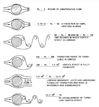
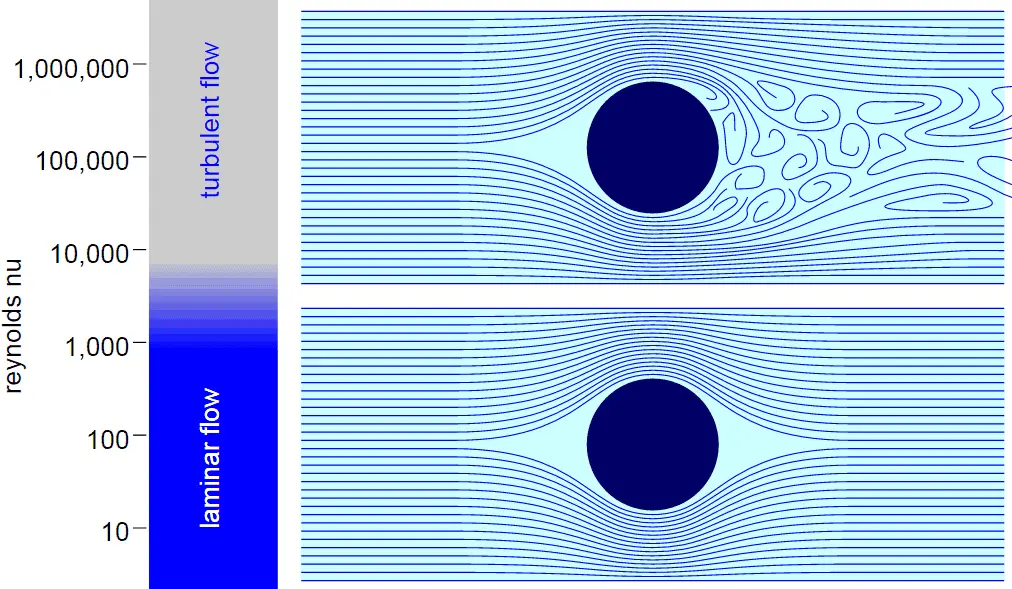
External Flow - tube
Tube in cross-flow.
Source: Blevins, R. D. (1990), Flow Induced Vibration, 2nd Edn., Van Nostrand Reinhold Co.
 
Classification of Flow Regimes
From a practical engineering point of view the flow regime can be categorized according to several criteria.

All fluid flow is classified into one of two broad categories or regimes. These two flow regimes are:

  • Single-phase Fluid Flow
  • Multi-phase Fluid Flow (or Two-phase Fluid Flow)

This is a basic classification. All of the fluid flow equations (e.g. Bernoulli’s Equation) and relationships that were discussed in this section (Fluid Dynamics) were derived for the flow of a single phase of fluid whether liquid or vapor. Solution of multi-phase fluid flow is very complex and difficult and therefore it is usually in advanced courses of fluid dynamics.

flow regimeAnother usually more common classification of flow regimes is according to the shape and type of streamlines. All fluid flow is classified into one of two broad categories. The fluid flow can be either laminar or turbulent and therefore these two categories are:

  • Laminar Flow
  • Turbulent Flow

Laminar flow is characterized by smooth or in regular paths of particles of the fluid. Therefore the laminar flow is also referred to as streamline or viscous flow. In contrast to laminar flow, turbulent flow is characterized by the irregular movement of particles of the fluid. The turbulent fluid does not flow in parallel layers, the lateral mixing is very high, and there is a disruption between the layers. Most industrial flows, especially those in nuclear engineering are turbulent.

The flow regime can be also classified according to the geometry of a conduit or flow area. From this point of view, we distinguish:

  • Internal Flow
  • External Flow

Internal flow is a flow for which the fluid is confined by a surface. Detailed knowledge of behaviour of internal flow regimes is of importance in engineering, because circular pipes can withstand high pressures and hence are used to convey liquids. On the other hand, external flow is such a flow in which boundary layers develop freely, without constraints imposed by adjacent surfaces. Detailed knowledge of behaviour of external flow regimes is of importance especially in aeronautics and aerodynamics.

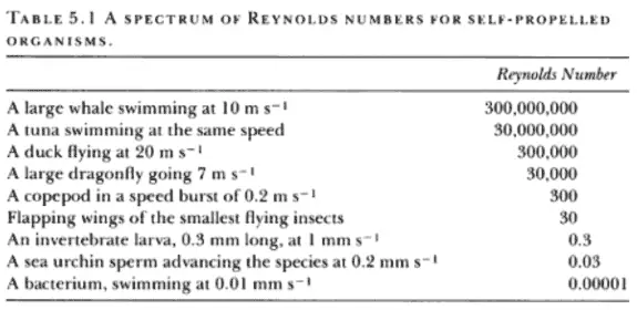
Table from Life in Moving Fluids
Table of Reynolds Numbers
Table from Life in Moving Fluids: The Physical Biology of Flow by Steven Vogel
Reynolds Number Regimes
flow regimeLaminar flow. For practical purposes, if the Reynolds number is less than 2000, the flow is laminar. The accepted transition Reynolds number for flow in a circular pipe is Red,crit = 2300.

Transitional flow. At Reynolds numbers between about 2000 and 4000 the flow is unstable as a result of the onset of turbulence. These flows are sometimes referred to as transitional flows.

Turbulent flow. If the Reynolds number is greater than 3500, the flow is turbulent. Most fluid systems in nuclear facilities operate with turbulent flow.

Charts: Viscosity and Density of Water (16MPa)
Viscosity of Water - 16MPa
Density of Water - 16 MPa

Turbulent Velocity Profile

velocity profiles - internal flow
Source: U.S. Department of Energy, THERMODYNAMICS, HEAT TRANSFER, AND FLUID FLOW. DOE Fundamentals Handbook, Volume 1, 2 and 3. June 1992.

Power-law velocity profile – Turbulent velocity profile

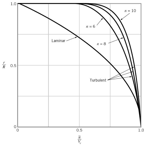
Power-law velocity profileThe velocity profile in turbulent flow is flatter in the central part of the pipe (i.e. in the turbulent core) than in laminar flow. The flow velocity drops rapidly extremely close to the walls. This is due to the diffusivity of the turbulent flow.

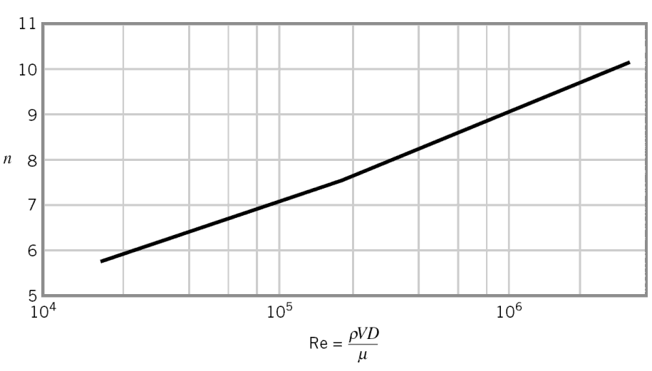
In case of turbulent pipe flow, there are many empirical velocity profiles. The simplest and the best known is the power-law velocity profile:

Power-law velocity profile - equation

where the exponent n is a constant whose value depends on the Reynolds number. This dependency is empirical and it is shown at the picture. In short, the value n increases with increasing Reynolds number. The one-seventh power-law velocity profile approximates many industrial flows.

Turbulent flow - profiles
Turbulent flow – profiles

Examples of Turbulent Flow

 
Example: Flow through a primary piping
The primary circuit of typical PWRs is divided into 4 independent loops (piping diameter ~ 700mm), each loop comprises a steam generator and one main coolant pump. the primary piping flow velocity is constant and equal to 17 m/s. The Reynolds number inside the primary piping is equal to:

ReD = 17 [m/s] x 0.7 [m] / 0.12×10⁻⁶ [m2/s] = 99 000 000.

This fully satisfies the turbulent conditions.

Example: Flow through a reactor core
Hydraulic Diameter
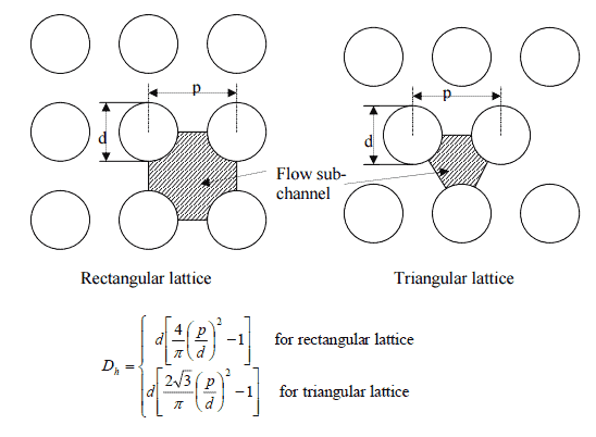
The hydraulic diameter of fuel rods bundle.

Inside the reactor pressure vessel of PWR, the coolant first flows down outside the reactor core (through the downcomer). From the bottom of the pressure vessel, the flow is reversed up through the core, where the coolant temperature increases as it passes through the fuel rods and the assemblies formed by them. The Reynolds number inside the fuel channel is equal to:

ReDH = 5 [m/s] x 0.01 [m] / 0.12×10⁻⁶ [m2/s] = 416 600.

This also fully satisfies the turbulent conditions.

See also: Hydraulic Diameter

Example: Smoke rising from a cigarette.
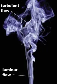
Reynolds number - smokeFor the first few centimeters, the flow is certainly laminar. However, at some point from the leading edge the flow will naturally transition to turbulent flow as its Reynolds number increases. The Reynolds number increases as its flow velocity and characteristic length are both increasing.

Turbulent Boundary Layer

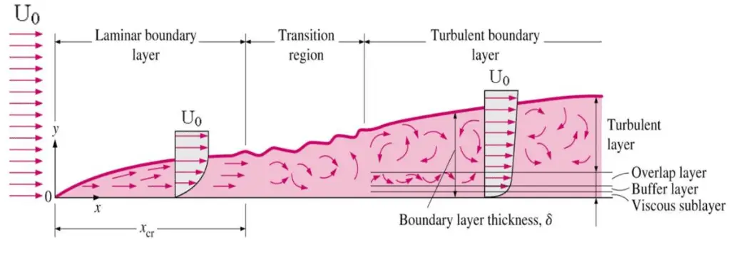
The concept of boundary layers is of importance in all of viscous fluid dynamics, aerodynamics, and also in the theory of heat transfer. Basic characteristics of all laminar and turbulent boundary layers are shown in the developing flow over a flat plate. The stages of the formation of the boundary layer are shown in the figure below:

Boundary layer on flat plate

Boundary layers may be either laminar, or turbulent depending on the value of the Reynolds number. Also here the Reynolds number represents the ratio of inertia forces to viscous forces and is a convenient parameter for predicting if a flow condition will be laminar or turbulent. It is defined as:

Reynolds number

in which V is the mean flow velocity, D a characteristic linear dimension, ρ fluid density, μ dynamic viscosity, and ν kinematic viscosity.

For lower Reynolds numbers, the boundary layer is laminar and the streamwise velocity changes uniformly as one moves away from the wall, as shown on the left side of the figure. As the Reynolds number increases (with x) the flow becomes unstable and finally for higher Reynolds numbers, the boundary layer is turbulent and the streamwise velocity is characterized by unsteady (changing with time) swirling flows inside the boundary layer.

Transition from laminar to turbulent boundary layer occurs when Reynolds number at x exceeds Rex ~ 500,000. Transition may occur earlier, but it is dependent especially on the surface roughness. The turbulent boundary layer thickens more rapidly than the laminar boundary layer as a result of increased shear stress at the body surface.

See also: Boundary layer thickness

See also: Tube in crossflow – external flow

Special reference: Schlichting Herrmann, Gersten Klaus. Boundary-Layer Theory, Springer-Verlag Berlin Heidelberg, 2000, ISBN: 978-3-540-66270-9

 
Example: Transition Layer
A long thin flat plate is placed parallel to a 1 m/s stream of water at 20°C. Assume that kinematic viscosity of water at 20°C is equal to 1×10⁻⁶ m2/s.

At what distance x from the leading edge will be the transition from laminar to turbulent boundary layer (i.e. find Rex ~ 500,000).

Solution:

In order to locate the transition from laminar to turbulent boundary layer, we have to find x at which Rex ~ 500,000.

x = 500 000 x 1×10-6 [m2/s] / 1 [m/s] = 0.5 m

Turbulent Flow – Heat Transfer Coefficient

External Turbulent Flow

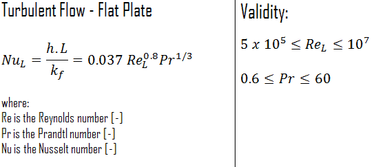
The average Nusselt number over the entire plate is determined by:

turbulent flow - flat plate - nusselt number

This relation gives the average heat transfer coefficient for the entire plate only when the flow is turbulent over the entire plate, or when the laminar flow region of the plate is too small relative to the turbulent flow region.

Internal Turbulent Flow – Dittus-Boelter

See also: Dittus-Boelter Equation

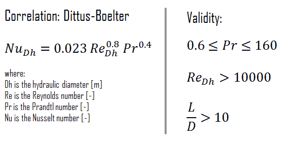
For fully developed (hydrodynamically and thermally) turbulent flow in a smooth circular tube, the local Nusselt number may be obtained from the well-known Dittus-Boelter equation. The Dittus–Boelter equation is easy to solve but is less accurate when there is a large temperature difference across the fluid and is less accurate for rough tubes (many commercial applications), since it is tailored to smooth tubes.

Dittus-Boelter Equation - Formula

The Dittus-Boelter correlation may be used for small to moderate temperature differences, Twall – Tavg, with all properties evaluated at an averaged temperature Tavg.

For flows characterized by large property variations, the corrections (e.g. a viscosity correction factor μ/μwall) must be taken into account, for example, as Sieder and Tate recommend.

Kolmogorov Microscales

In the view of Kolmogorov (Andrey Nikolaevich Kolmogorov was a Russian mathematician who made significant contributions to the mathematics of probability theory and turbulence), turbulent motions involve a wide range of scales. From a macroscale at which the energy is supplied, to a microscale at which energy is dissipated by viscosity.

For example, consider a cumulus cloud. The macroscale of the cloud can be of the order of kilometers and may grow or persist over long periods of time. Within the cloud, eddies may occur over scales of the order of millimeters. For smaller flows such as in pipes, the microscales may be much smaller. Most of the kinetic energy of the turbulent flow is contained in the macroscale structures. The energy “cascades” from these macroscale structures to microscale structures by an inertial mechanism. This process is known as the turbulent energy cascade.

The smallest scales in turbulent flow are known as the Kolmogorov microscales. These are small enough that molecular diffusion becomes important and viscous dissipation of energy takes place and the turbulent kinetic energy is dissipated into heat.

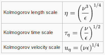
The smallest scales in turbulent flow, i.e. the Kolmogorov microscales are:

kolmogorov microscales

where ε is the average rate of dissipation rate of turbulence kinetic energy per unit mass and has dimensions (m2/s3). ν is the kinematic viscosity of the fluid and has dimensions (m2/s).

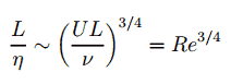
The size of the smallest eddy in the flow is determined by viscosity. The Kolmogorov length scale decreases as viscosity decreases. For very high Reynolds number flows, the viscous forces are smaller with respect to inertial forces. Smaller scale motions are then necessarily generated until the effects of viscosity become important and energy is dissipated. The ratio of largest to smallest length scales in the turbulent flow are proportional to the Reynolds number (raises with the three-quarters power).

kolmogorov microscales - equation

This causes direct numerical simulations of turbulent flow to be practically impossible. For example, consider a flow with a Reynolds number of 106. In this case the ratio L/l is proportional to 1018/4. Since we have to analyze three-dimensional problem, we need to compute a grid that consisted of at least 1014 grid points. This far exceeds the capacity and  possibilities of existing computers.

 
References:
Reactor Physics and Thermal Hydraulics:
  1. J. R. Lamarsh, Introduction to Nuclear Reactor Theory, 2nd ed., Addison-Wesley, Reading, MA (1983).
  2. J. R. Lamarsh, A. J. Baratta, Introduction to Nuclear Engineering, 3d ed., Prentice-Hall, 2001, ISBN: 0-201-82498-1.
  3. W. M. Stacey, Nuclear Reactor Physics, John Wiley & Sons, 2001, ISBN: 0- 471-39127-1.
  4. Glasstone, Sesonske. Nuclear Reactor Engineering: Reactor Systems Engineering, Springer; 4th edition, 1994, ISBN: 978-0412985317
  5. Todreas Neil E., Kazimi Mujid S. Nuclear Systems Volume I: Thermal Hydraulic Fundamentals, Second Edition. CRC Press; 2 edition, 2012, ISBN: 978-0415802871
  6. Zohuri B., McDaniel P. Thermodynamics in Nuclear Power Plant Systems. Springer; 2015, ISBN: 978-3-319-13419-2
  7. Moran Michal J., Shapiro Howard N. Fundamentals of Engineering Thermodynamics, Fifth Edition, John Wiley & Sons, 2006, ISBN: 978-0-470-03037-0
  8. Kleinstreuer C. Modern Fluid Dynamics. Springer, 2010, ISBN 978-1-4020-8670-0.
  9. U.S. Department of Energy, THERMODYNAMICS, HEAT TRANSFER, AND FLUID FLOW. DOE Fundamentals Handbook, Volume 1, 2 and 3. June 1992.
  10. White Frank M., Fluid Mechanics, McGraw-Hill Education, 7th edition, February, 2010, ISBN: 978-0077422417

See also:

Fluid Dynamics

We hope, this article, Turbulent Flow, helps you. If so, give us a like in the sidebar. Main purpose of this website is to help the public to learn some interesting and important information about thermal engineering.
What is Power-law velocity profile – Turbulent Flow – Definition

The velocity profile in turbulent flow is flatter in the central part of the pipe. The simplest and the best known is the power-law velocity profile. Thermal Engineering

Turbulent Velocity Profile

velocity profiles - internal flow
Source: U.S. Department of Energy, THERMODYNAMICS, HEAT TRANSFER, AND FLUID FLOW. DOE Fundamentals Handbook, Volume 1, 2 and 3. June 1992.

Power-law velocity profile – Turbulent velocity profile

Power-law velocity profileThe velocity profile in turbulent flow is flatter in the central part of the pipe (i.e. in the turbulent core) than in laminar flow. The flow velocity drops rapidly extremely close to the walls. This is due to the diffusivity of the turbulent flow.

In case of turbulent pipe flow, there are many empirical velocity profiles. The simplest and the best known is the power-law velocity profile:

Power-law velocity profile - equation

where the exponent n is a constant whose value depends on the Reynolds number. This dependency is empirical and it is shown at the picture. In short, the value n increases with increasing Reynolds number. The one-seventh power-law velocity profile approximates many industrial flows.

Turbulent flow - profiles
Turbulent flow – profiles
 
References:
Reactor Physics and Thermal Hydraulics:
  1. J. R. Lamarsh, Introduction to Nuclear Reactor Theory, 2nd ed., Addison-Wesley, Reading, MA (1983).
  2. J. R. Lamarsh, A. J. Baratta, Introduction to Nuclear Engineering, 3d ed., Prentice-Hall, 2001, ISBN: 0-201-82498-1.
  3. W. M. Stacey, Nuclear Reactor Physics, John Wiley & Sons, 2001, ISBN: 0- 471-39127-1.
  4. Glasstone, Sesonske. Nuclear Reactor Engineering: Reactor Systems Engineering, Springer; 4th edition, 1994, ISBN: 978-0412985317
  5. Todreas Neil E., Kazimi Mujid S. Nuclear Systems Volume I: Thermal Hydraulic Fundamentals, Second Edition. CRC Press; 2 edition, 2012, ISBN: 978-0415802871
  6. Zohuri B., McDaniel P. Thermodynamics in Nuclear Power Plant Systems. Springer; 2015, ISBN: 978-3-319-13419-2
  7. Moran Michal J., Shapiro Howard N. Fundamentals of Engineering Thermodynamics, Fifth Edition, John Wiley & Sons, 2006, ISBN: 978-0-470-03037-0
  8. Kleinstreuer C. Modern Fluid Dynamics. Springer, 2010, ISBN 978-1-4020-8670-0.
  9. U.S. Department of Energy, THERMODYNAMICS, HEAT TRANSFER, AND FLUID FLOW. DOE Fundamentals Handbook, Volume 1, 2 and 3. June 1992.
  10. White Frank M., Fluid Mechanics, McGraw-Hill Education, 7th edition, February, 2010, ISBN: 978-0077422417

See also:

Turbulent Flow

We hope, this article, Power-law velocity profile – Turbulent Flow, helps you. If so, give us a like in the sidebar. Main purpose of this website is to help the public to learn some interesting and important information about thermal engineering.
What is Characteristics of Turbulent Flow – Definition

Characteristics of turbulent flow. Turbulent flow tends to occur at higher velocities, low viscosity and at higher characteristic linear dimensions. Thermal Engineering

Characteristics of Turbulent Flow

  • Turbulent flow tends to occur at higher velocities, low viscosity and at higher characteristic linear dimensions.
  • If the Reynolds number is greater than Re > 3500, the flow is turbulent.
  • Irregularity: The flow is characterized by the irregular movement of particles of the fluid. The movement of fluid particles is chaotic. For this reason, turbulent flow is normally treated statistically rather than deterministically.
  • Diffusivity: In turbulent flow, a fairly flat velocity distribution exists across the section of pipe, with the result that the entire fluid flows at a given single value and drops rapidly extremely close to the walls. The characteristic which is responsible for the enhanced mixing and increased rates of mass, momentum and energy transports in a flow is called “diffusivity”.
  • Rotationality: Turbulent flow is characterized by a strong three-dimensional vortex generation mechanism. This mechanism is known as vortex stretching.
  • Dissipation: A dissipative process is a process in which the kinetic energy of turbulent flow is transformed into internal energy by viscous shear stress.
External Flow - tube
Tube in cross-flow.
Source: Blevins, R. D. (1990), Flow Induced Vibration, 2nd Edn., Van Nostrand Reinhold Co.

Laminar vs. Turbulent Flow

Laminar vs. Turbulent Flow

Laminar flow:

  • Re < 2000
  • ‘low’ velocity
  • Fluid particles move in straight lines
  • Layers of water flow over one another at different speeds with virtually no mixing between layers.
  • The flow velocity profile for laminar flow in circular pipes is parabolic in shape, with a maximum flow in the center of the pipe and a minimum flow at the pipe walls.
  • The average flow velocity is approximately one half of the maximum velocity.
  • Simple mathematical analysis is possible.
  • Rare in practice in water systems.

Turbulent Flow:

  • Re > 4000
  • ‘high’ velocity
  • The flow is characterized by the irregular movement of particles of the fluid.
  • Average motion is in the direction of the flow
  • The flow velocity profile for turbulent flow is fairly flat across the center section of a pipe and drops rapidly extremely close to the walls.
  • The average flow velocity is approximately equal to the velocity at the center of the pipe.
  • Mathematical analysis is very difficult.
  • Most common type of flow.
 
References:
Reactor Physics and Thermal Hydraulics:
  1. J. R. Lamarsh, Introduction to Nuclear Reactor Theory, 2nd ed., Addison-Wesley, Reading, MA (1983).
  2. J. R. Lamarsh, A. J. Baratta, Introduction to Nuclear Engineering, 3d ed., Prentice-Hall, 2001, ISBN: 0-201-82498-1.
  3. W. M. Stacey, Nuclear Reactor Physics, John Wiley & Sons, 2001, ISBN: 0- 471-39127-1.
  4. Glasstone, Sesonske. Nuclear Reactor Engineering: Reactor Systems Engineering, Springer; 4th edition, 1994, ISBN: 978-0412985317
  5. Todreas Neil E., Kazimi Mujid S. Nuclear Systems Volume I: Thermal Hydraulic Fundamentals, Second Edition. CRC Press; 2 edition, 2012, ISBN: 978-0415802871
  6. Zohuri B., McDaniel P. Thermodynamics in Nuclear Power Plant Systems. Springer; 2015, ISBN: 978-3-319-13419-2
  7. Moran Michal J., Shapiro Howard N. Fundamentals of Engineering Thermodynamics, Fifth Edition, John Wiley & Sons, 2006, ISBN: 978-0-470-03037-0
  8. Kleinstreuer C. Modern Fluid Dynamics. Springer, 2010, ISBN 978-1-4020-8670-0.
  9. U.S. Department of Energy, THERMODYNAMICS, HEAT TRANSFER, AND FLUID FLOW. DOE Fundamentals Handbook, Volume 1, 2 and 3. June 1992.
  10. White Frank M., Fluid Mechanics, McGraw-Hill Education, 7th edition, February, 2010, ISBN: 978-0077422417

See also:

Turbulent Flow

We hope, this article, Characteristics of Turbulent Flow, helps you. If so, give us a like in the sidebar. Main purpose of this website is to help the public to learn some interesting and important information about thermal engineering.
What is Example of Turbulent Flow – Definition

Examples of turbulent flow. There are several examples of turbulent flow from life and from industry. Most industrial flows are turbulent, especially in power engineering. Thermal Engineering
 
What is turbulent flow
In fluid dynamics, turbulent flow is characterized by the irregular movement of particles (one can say chaotic) of the fluid. In contrast to laminar flow the fluid does not flow in parallel layers, the lateral mixing is very high, and there is a disruption between the layers. Turbulence is also characterized by recirculation, eddies, and apparent randomness. In turbulent flow the speed of the fluid at a point is continuously undergoing changes in both magnitude and direction.

Detailed knowledge of behaviour of turbulent flow regime is of importance in engineering, because most industrial flows, especially those in nuclear engineering are turbulent. Unfortunately, the highly intermittent and irregular character of turbulence complicates all analyses. In fact, turbulence is often said to be the “last unsolved problem in classical mathemetical physics.”

The main tool available for their analysis is CFD analysis. CFD is a branch of fluid mechanics that uses numerical analysis and algorithms to solve and analyze problems that involve turbulent fluid flows. It is widely accepted that the Navier–Stokes equations (or simplified Reynolds-averaged Navier–Stokes equations) are capable of exhibiting turbulent solutions, and these equations are the basis for essentially all CFD codes.

See also: Internal Flow

See also: External Flow

Examples of Turbulent Flow

Table of Reynolds Numbers
Table from Life in Moving Fluids: The Physical Biology of Flow by Steven Vogel

Example: Turbulent flow in a primary piping

Continuity Equation - Flow Rates through Reactor
Example of flow rates in a reactor. It is an illustrative example, data do not represent any reactor design.

The primary circuit of typical PWRs is divided into 4 independent loops (piping diameter ~ 700mm), each loop comprises a steam generator and one main coolant pump. the primary piping flow velocity is constant and equal to 17 m/s. The Reynolds number inside the primary piping is equal to:

ReD = 17 [m/s] x 0.7 [m] / 0.12×10⁻⁶ [m2/s] = 99 000 000.

This fully satisfies the turbulent conditions.

Example: Turbulent flow in a reactor core

Hydraulic Diameter
The hydraulic diameter of fuel rods bundle.

Inside the reactor pressure vessel of PWR, the coolant first flows down outside the reactor core (through the downcomer). From the bottom of the pressure vessel, the flow is reversed up through the core, where the coolant temperature increases as it passes through the fuel rods and the assemblies formed by them. The Reynolds number inside the fuel channel is equal to:

ReDH = 5 [m/s] x 0.02 [m] / 0.12×10⁻⁶ [m2/s] = 833 000.

This also fully satisfies the turbulent conditions.

See also: Hydraulic Diameter

Example: Smoke rising from a cigarette

Reynolds number - smokeFor the first few centimeters, the flow is certainly laminar. However, at some point from the leading edge the flow will naturally transition to turbulent flow as its Reynolds number increases. The Reynolds number increases as its flow velocity and characteristic length are both increasing.

 
References:
Reactor Physics and Thermal Hydraulics:
  1. J. R. Lamarsh, Introduction to Nuclear Reactor Theory, 2nd ed., Addison-Wesley, Reading, MA (1983).
  2. J. R. Lamarsh, A. J. Baratta, Introduction to Nuclear Engineering, 3d ed., Prentice-Hall, 2001, ISBN: 0-201-82498-1.
  3. W. M. Stacey, Nuclear Reactor Physics, John Wiley & Sons, 2001, ISBN: 0- 471-39127-1.
  4. Glasstone, Sesonske. Nuclear Reactor Engineering: Reactor Systems Engineering, Springer; 4th edition, 1994, ISBN: 978-0412985317
  5. Todreas Neil E., Kazimi Mujid S. Nuclear Systems Volume I: Thermal Hydraulic Fundamentals, Second Edition. CRC Press; 2 edition, 2012, ISBN: 978-0415802871
  6. Zohuri B., McDaniel P. Thermodynamics in Nuclear Power Plant Systems. Springer; 2015, ISBN: 978-3-319-13419-2
  7. Moran Michal J., Shapiro Howard N. Fundamentals of Engineering Thermodynamics, Fifth Edition, John Wiley & Sons, 2006, ISBN: 978-0-470-03037-0
  8. Kleinstreuer C. Modern Fluid Dynamics. Springer, 2010, ISBN 978-1-4020-8670-0.
  9. U.S. Department of Energy, THERMODYNAMICS, HEAT TRANSFER, AND FLUID FLOW. DOE Fundamentals Handbook, Volume 1, 2 and 3. June 1992.
  10. White Frank M., Fluid Mechanics, McGraw-Hill Education, 7th edition, February, 2010, ISBN: 978-0077422417

See also:

Turbulent Flow

We hope, this article, Example of Turbulent Flow, helps you. If so, give us a like in the sidebar. Main purpose of this website is to help the public to learn some interesting and important information about thermal engineering.
What is Turbulent Boundary Layer – Definition

Turbulent Boundary Layer. Boundary layers may be either laminar, or turbulent depending on the value of the Reynolds number. For high Reynolds number the boundary layer is turbulent. Thermal Engineering

Turbulent Boundary Layer

The concept of boundary layers is of importance in all of viscous fluid dynamics, aerodynamics, and also in the theory of heat transfer. Basic characteristics of all laminar and turbulent boundary layers are shown in the developing flow over a flat plate. The stages of the formation of the boundary layer are shown in the figure below:

Boundary layer on flat plate

Boundary layers may be either laminar, or turbulent depending on the value of the Reynolds number. Also here the Reynolds number represents the ratio of inertia forces to viscous forces and is a convenient parameter for predicting if a flow condition will be laminar or turbulent. It is defined as:

Reynolds number

in which V is the mean flow velocity, D a characteristic linear dimension, ρ fluid density, μ dynamic viscosity, and ν kinematic viscosity.

For lower Reynolds numbers, the boundary layer is laminar and the streamwise velocity changes uniformly as one moves away from the wall, as shown on the left side of the figure. As the Reynolds number increases (with x) the flow becomes unstable and finally for higher Reynolds numbers, the boundary layer is turbulent and the streamwise velocity is characterized by unsteady (changing with time) swirling flows inside the boundary layer.

Transition from laminar to turbulent boundary layer occurs when Reynolds number at x exceeds Rex ~ 500,000. Transition may occur earlier, but it is dependent especially on the surface roughness. The turbulent boundary layer thickens more rapidly than the laminar boundary layer as a result of increased shear stress at the body surface.

See also: Boundary layer thickness

See also: Tube in crossflow – external flow

Special reference: Schlichting Herrmann, Gersten Klaus. Boundary-Layer Theory, Springer-Verlag Berlin Heidelberg, 2000, ISBN: 978-3-540-66270-9

 
Example: Transition Layer
A long thin flat plate is placed parallel to a 1 m/s stream of water at 20°C. Assume that kinematic viscosity of water at 20°C is equal to 1×10⁻⁶ m2/s.

At what distance x from the leading edge will be the transition from laminar to turbulent boundary layer (i.e. find Rex ~ 500,000).

Solution:

In order to locate the transition from laminar to turbulent boundary layer, we have to find x at which Rex ~ 500,000.

x = 500 000 x 1×10-6 [m2/s] / 1 [m/s] = 0.5 m

 
References:
Reactor Physics and Thermal Hydraulics:
  1. J. R. Lamarsh, Introduction to Nuclear Reactor Theory, 2nd ed., Addison-Wesley, Reading, MA (1983).
  2. J. R. Lamarsh, A. J. Baratta, Introduction to Nuclear Engineering, 3d ed., Prentice-Hall, 2001, ISBN: 0-201-82498-1.
  3. W. M. Stacey, Nuclear Reactor Physics, John Wiley & Sons, 2001, ISBN: 0- 471-39127-1.
  4. Glasstone, Sesonske. Nuclear Reactor Engineering: Reactor Systems Engineering, Springer; 4th edition, 1994, ISBN: 978-0412985317
  5. Todreas Neil E., Kazimi Mujid S. Nuclear Systems Volume I: Thermal Hydraulic Fundamentals, Second Edition. CRC Press; 2 edition, 2012, ISBN: 978-0415802871
  6. Zohuri B., McDaniel P. Thermodynamics in Nuclear Power Plant Systems. Springer; 2015, ISBN: 978-3-319-13419-2
  7. Moran Michal J., Shapiro Howard N. Fundamentals of Engineering Thermodynamics, Fifth Edition, John Wiley & Sons, 2006, ISBN: 978-0-470-03037-0
  8. Kleinstreuer C. Modern Fluid Dynamics. Springer, 2010, ISBN 978-1-4020-8670-0.
  9. U.S. Department of Energy, THERMODYNAMICS, HEAT TRANSFER, AND FLUID FLOW. DOE Fundamentals Handbook, Volume 1, 2 and 3. June 1992.
  10. White Frank M., Fluid Mechanics, McGraw-Hill Education, 7th edition, February, 2010, ISBN: 978-0077422417

See also:

Turbulent Flow

We hope, this article, Turbulent Boundary Layer, helps you. If so, give us a like in the sidebar. Main purpose of this website is to help the public to learn some interesting and important information about thermal engineering.
What is Kolmogorov Microscale – Definition

Turbulent motions involve a wide range of scales. From a macroscale at which the energy is supplied, to a Kolmogorov microscale at which energy is dissipated by viscosity. Thermal Engineering

Kolmogorov Microscales

In the view of Kolmogorov (Andrey Nikolaevich Kolmogorov was a Russian mathematician who made significant contributions to the mathematics of probability theory and turbulence), turbulent motions involve a wide range of scales. From a macroscale at which the energy is supplied, to a microscale at which energy is dissipated by viscosity.

For example, consider a cumulus cloud. The macroscale of the cloud can be of the order of kilometers and may grow or persist over long periods of time. Within the cloud, eddies may occur over scales of the order of millimeters. For smaller flows such as in pipes, the microscales may be much smaller. Most of the kinetic energy of the turbulent flow is contained in the macroscale structures. The energy “cascades” from these macroscale structures to microscale structures by an inertial mechanism. This process is known as the turbulent energy cascade.

The smallest scales in turbulent flow are known as the Kolmogorov microscales. These are small enough that molecular diffusion becomes important and viscous dissipation of energy takes place and the turbulent kinetic energy is dissipated into heat.

The smallest scales in turbulent flow, i.e. the Kolmogorov microscales are:

kolmogorov microscales

where ε is the average rate of dissipation rate of turbulence kinetic energy per unit mass and has dimensions (m2/s3). ν is the kinematic viscosity of the fluid and has dimensions (m2/s).

The size of the smallest eddy in the flow is determined by viscosity. The Kolmogorov length scale decreases as viscosity decreases. For very high Reynolds number flows, the viscous forces are smaller with respect to inertial forces. Smaller scale motions are then necessarily generated until the effects of viscosity become important and energy is dissipated. The ratio of largest to smallest length scales in the turbulent flow are proportional to the Reynolds number (raises with the three-quarters power).

kolmogorov microscales - equation

This causes direct numerical simulations of turbulent flow to be practically impossible. For example, consider a flow with a Reynolds number of 106. In this case the ratio L/l is proportional to 1018/4. Since we have to analyze three-dimensional problem, we need to compute a grid that consisted of at least 1014 grid points. This far exceeds the capacity and  possibilities of existing computers.

 
References:
Reactor Physics and Thermal Hydraulics:
  1. J. R. Lamarsh, Introduction to Nuclear Reactor Theory, 2nd ed., Addison-Wesley, Reading, MA (1983).
  2. J. R. Lamarsh, A. J. Baratta, Introduction to Nuclear Engineering, 3d ed., Prentice-Hall, 2001, ISBN: 0-201-82498-1.
  3. W. M. Stacey, Nuclear Reactor Physics, John Wiley & Sons, 2001, ISBN: 0- 471-39127-1.
  4. Glasstone, Sesonske. Nuclear Reactor Engineering: Reactor Systems Engineering, Springer; 4th edition, 1994, ISBN: 978-0412985317
  5. Todreas Neil E., Kazimi Mujid S. Nuclear Systems Volume I: Thermal Hydraulic Fundamentals, Second Edition. CRC Press; 2 edition, 2012, ISBN: 978-0415802871
  6. Zohuri B., McDaniel P. Thermodynamics in Nuclear Power Plant Systems. Springer; 2015, ISBN: 978-3-319-13419-2
  7. Moran Michal J., Shapiro Howard N. Fundamentals of Engineering Thermodynamics, Fifth Edition, John Wiley & Sons, 2006, ISBN: 978-0-470-03037-0
  8. Kleinstreuer C. Modern Fluid Dynamics. Springer, 2010, ISBN 978-1-4020-8670-0.
  9. U.S. Department of Energy, THERMODYNAMICS, HEAT TRANSFER, AND FLUID FLOW. DOE Fundamentals Handbook, Volume 1, 2 and 3. June 1992.
  10. White Frank M., Fluid Mechanics, McGraw-Hill Education, 7th edition, February, 2010, ISBN: 978-0077422417

See also:

Turbulent Flow

We hope, this article, Kolmogorov Microscale, helps you. If so, give us a like in the sidebar. Main purpose of this website is to help the public to learn some interesting and important information about thermal engineering.

What is Classification of Head Loss – Definition

Classification of Head Loss.The head loss of piping system is divided into two main categories, major losses and minod head losses. Thermal Engineering

Classification of Head Loss

The head loss of a pipe, tube or duct system, is the same as that produced in a straight pipe or duct whose length is equal to the pipes of the original systems plus the sum of the equivalent lengths of all the components in the system.

As can be seen, the head loss of piping system is divided into two main categories, “major losses” associated with energy loss per length of pipe, and “minor losses” associated with bends, fittings, valves, etc.

  • Major Head Loss – due to friction in pipes and ducts.
  • Minor Head Loss – due to components as valves, fittings, bends and tees.

The head loss can be then expressed as:

hloss = Σ hmajor_losses + Σ hminor_losses

Summary:

  • Head loss or pressure loss are the reduction in the total head (sum of potential head, velocity head, and pressure head) of a fluid caused by the friction present in the fluid’s motion.
  • Head loss and pressure loss represent the same phenomenon – frictional losses in pipe and losses in hydraulic components, but they are expressed in different units.
  • Head loss of hydraulic system is divided into two main categories:
    • Major Head Loss – due to friction in straight pipes
    • Minor Head Loss – due to components as valves, bends…
  • Darcy’s equation can be used to calculate major losses.
  • A special form of Darcy’s equation can be used to calculate minor losses.
  • The friction factor for fluid flow can be determined using a Moody chart.

Why the head loss is very important?

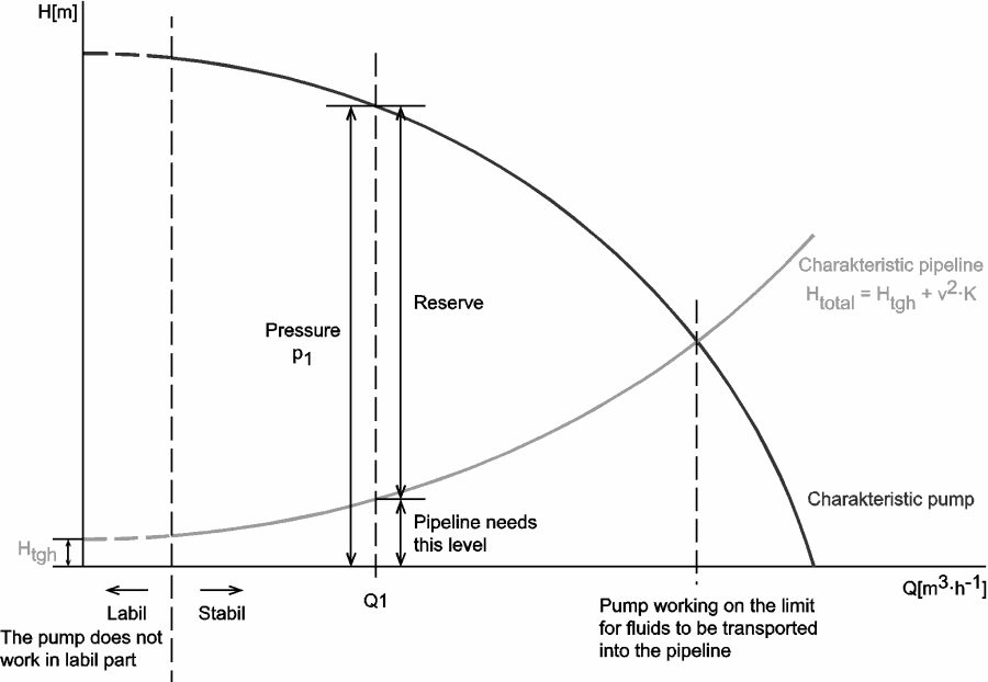
As can be seen from the picture, the head loss is forms key characteristic of any hydraulic system. In systems, in which some certain flowrate must be maintained (e.g. to provide sufficient cooling or heat transfer from a reactor core), the equilibrium of the head loss and the head added by a pump determines the flowrate through the system.

Q-H characteristic diagram of centrifugal pump and of pipeline
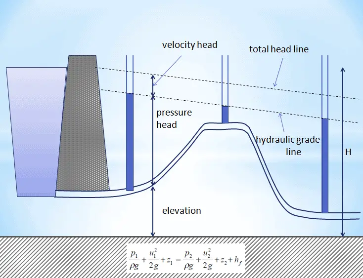
Hydraulic Head - Hydraulic Grade Line
Hydraulic grade line and Total head lines for a constant diameter pipe with friction. In a real pipe line there are energy losses due to friction – these must be taken into account as they can be very significant.
 
References:
Reactor Physics and Thermal Hydraulics:
  1. J. R. Lamarsh, Introduction to Nuclear Reactor Theory, 2nd ed., Addison-Wesley, Reading, MA (1983).
  2. J. R. Lamarsh, A. J. Baratta, Introduction to Nuclear Engineering, 3d ed., Prentice-Hall, 2001, ISBN: 0-201-82498-1.
  3. W. M. Stacey, Nuclear Reactor Physics, John Wiley & Sons, 2001, ISBN: 0- 471-39127-1.
  4. Glasstone, Sesonske. Nuclear Reactor Engineering: Reactor Systems Engineering, Springer; 4th edition, 1994, ISBN: 978-0412985317
  5. Todreas Neil E., Kazimi Mujid S. Nuclear Systems Volume I: Thermal Hydraulic Fundamentals, Second Edition. CRC Press; 2 edition, 2012, ISBN: 978-0415802871
  6. Zohuri B., McDaniel P. Thermodynamics in Nuclear Power Plant Systems. Springer; 2015, ISBN: 978-3-319-13419-2
  7. Moran Michal J., Shapiro Howard N. Fundamentals of Engineering Thermodynamics, Fifth Edition, John Wiley & Sons, 2006, ISBN: 978-0-470-03037-0
  8. Kleinstreuer C. Modern Fluid Dynamics. Springer, 2010, ISBN 978-1-4020-8670-0.
  9. U.S. Department of Energy, THERMODYNAMICS, HEAT TRANSFER, AND FLUID FLOW. DOE Fundamentals Handbook, Volume 1, 2 and 3. June 1992.
  10. White Frank M., Fluid Mechanics, McGraw-Hill Education, 7th edition, February, 2010, ISBN: 978-0077422417

See also:

Head Loss

We hope, this article, Classification of Head Loss, helps you. If so, give us a like in the sidebar. Main purpose of this website is to help the public to learn some interesting and important information about thermal engineering.
What is Major Head Loss – Friction Loss – Definition

Major head losses, which are associated with frictional energy loss per length of pipe is of importance in hydraulic systems design. Friction Loss in Pipe. Thermal Engineering
The Hydraulic Head
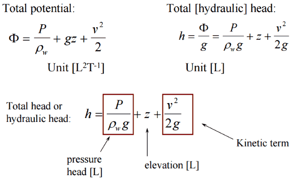
In general, the hydraulic head, or total head, is a measure of the potential of fluid at the measurement point. It can be used to determine a hydraulic gradient between two or more points.
Bernoulli Theorem - Equation

In fluid dynamics, head is a concept that relates the energy in an incompressible fluid to the height of an equivalent static column of that fluid. The units for all the different forms of energy in the Bernoulli’s equation can be measured also in units of distance, and therefore these terms are sometimes referred to as “heads” (pressure head, velocity head, and elevation head). Head is also defined for pumps. This head is usually referred to as the static head and represents the maximum height (pressure) it can deliver. Therefore the characteristics of all pumps can be usually read from its Q-H curve (flow rate – height).

There are four types of potential (head):

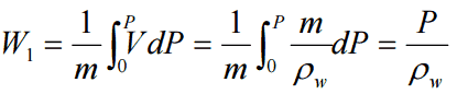
  • Pressure potential – Pressure head: The pressure head represents the flow energy of a column of fluid whose weight is equivalent to the pressure of the fluid.Pressure Headρw: density of water assumed to be independent of pressure
  • Elevation potential – Elevation head: The elevation head represents the potential energy of a fluid due to its elevation above a reference level.Elevation Head
  • Kinetic potential – Kinetic head: The kinetic head represents the kinetic energy of the fluid. It is the height in feet that a flowing fluid would rise in a column if all of its kinetic energy were converted to potential energy.Kinetic Head

The sum of the elevation head, kinetic head, and pressure head of a fluid is called the total head. Thus, Bernoulli’s equation states that the total head of the fluid is constant.

Total Hydraulic Head

Consider a pipe containing an ideal fluid. If this pipe undergoes a gradual expansion in diameter, the continuity equation tells us that as the pipe diameter increases, the flow velocity must decrease in order to maintain the same mass flow rate. Since the outlet velocity is less than the inlet velocity, the kinetic head of the flow must decrease from the inlet to the outlet. If there is no change in elevation head (the pipe lies horizontal), the decrease in kinetic head must be compensated for by an increase in pressure head.

Classification of Head Loss
The head loss of a pipe, tube or duct system, is the same as that produced in a straight pipe or duct whose length is equal to the pipes of the original systems plus the sum of the equivalent lengths of all the components in the system.

As can be seen, the head loss of piping system is divided into two main categories, “major losses” associated with energy loss per length of pipe, and “minor losses” associated with bends, fittings, valves, etc.

  • Major Head Loss – due to friction in pipes and ducts.
  • Minor Head Loss – due to components as valves, fittings, bends and tees.

The head loss can be then expressed as:

hloss = Σ hmajor_losses + Σ hminor_losses

Major Head Loss – Frictional Loss

Major losses, which are associated with frictional energy loss per length of pipe depends on the flow velocity, pipe length, pipe diameter, and a friction factor based on the roughness of the pipe, and whether the flow is laminar or turbulent (i.e. the Reynolds number of the flow).

Although the head loss represents a loss of energy, it does not represent a loss of total energy of the fluid. The total energy of the fluid conserves as a consequence of the law of conservation of energy. In reality, the head loss due to friction results in an equivalent increase in the internal energy (increase in temperature) of the fluid.

By observation, the major head loss is roughly proportional to the square of the flow rate in most engineering flows (fully developed, turbulent pipe flow).

The most common equation used to calculate major head losses in a tube or duct is the Darcy–Weisbach equation .

Darcy-Weisbach Equation

In fluid dynamics, the Darcy–Weisbach equation is a phenomenological equation, which relates the major head loss, or pressure loss, due to fluid friction along a given length of pipe to the average velocity. This equation is valid for fully developed, steady, incompressible single-phase flow.

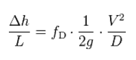
The Darcy–Weisbach equation can be written in two forms (pressure loss form or head loss form). In the head loss form can be written as:

Major Head Loss - head form

where:

  • Δh = the head loss due to friction (m)
  • fD = the Darcy friction factor (unitless)
  • L = the pipe length (m)
  • D = the hydraulic diameter of the pipe D (m)
  • g = the gravitational constant (m/s2)
  • V = the mean flow velocity V (m/s)
Pressure loss form
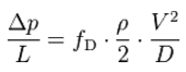
The Darcy–Weisbach equation in the pressure loss form can be written as:
Major Head Loss - pressure loss form

where:

  • Δp = the pressure loss due to friction (Pa)
  • fD = the Darcy friction factor (unitless)
  • L = the pipe length (m)
  • D = the hydraulic diameter of the pipe D (m)
  • g = the gravitational constant (m/s2)
  • V = the mean flow velocity V (m/s)

___________

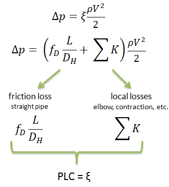
Pressure Loss Coefficient - PLC
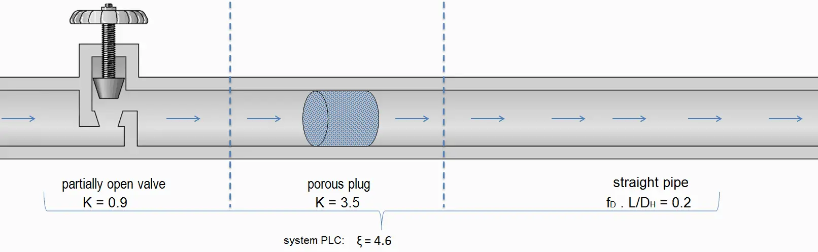
Sometimes, engineers use the pressure loss coefficient, PLC. It is noted K or ξ  (pronounced “xi”). This coefficient characterizes pressure loss of a certain hydraulic system or of a part of a hydraulic system. It can be easily measured in hydraulic loops. The pressure loss coefficient can be defined or measured for both straight pipes and especially for local (minor) losses.

PLC - Pressure loss coefficient - equations

Example - pressure loss coefficient

Summary:

  • Head loss of hydraulic system is divided into two main categories:
    • Major Head Loss – due to friction in straight pipes
    • Minor Head Loss – due to components as valves, bends…
  • Darcy’s equation can be used to calculate major losses.
  • The friction factor for fluid flow can be determined using a Moody chart.Moody chart-min
  • The friction factor for laminar flow is independent of roughness of the pipe’s inner surface. f = 64/Re
  • The friction factor for turbulent flow depends strongly on the relative roughness. It is determined by the Colebrook equation. It must be noted, at very large Reynolds numbers, the friction factor is independent of the Reynolds number.

Why the head loss is very important?

As can be seen from the picture, the head loss is forms key characteristic of any hydraulic system. In systems, in which some certain flowrate must be maintained (e.g. to provide sufficient cooling or heat transfer from a reactor core), the equilibrium of the head loss and the head added by a pump determines the flowrate through the system.

Q-H characteristic diagram of centrifugal pump and of pipeline
Hydraulic Head - Hydraulic Grade Line
Hydraulic grade line and Total head lines for a constant diameter pipe with friction. In a real pipe line there are energy losses due to friction – these must be taken into account as they can be very significant.
Evaluating the Darcy-Weisbach equation provides insight into factors affecting the head loss in a pipeline.
  • Consider that the length of the pipe or channel is doubled, the resulting frictional head loss will double.
  • At constant flow rate and pipe length, the head loss is inversely proportional to the 4th power of diameter (for laminar flow), and thus reducing the pipe diameter by half increases the head loss by a factor of 16. This is a very significant increase in head loss, and shows why larger diameter pipes lead to much smaller pumping power requirements.
  • Since the head loss is roughly proportional to the square of the flow rate, then if the flow rate is doubled, the head loss increases by a factor of four.
  • The head loss is reduced by half (for laminar flow) when the viscosity of the fluid is reduced by half.
Source: Donebythesecondlaw at the English language Wikipedia, CC BY-SA 3.0, https://commons.wikimedia.org/w/index.php?curid=4681366
Source: Donebythesecondlaw at the English language Wikipedia, CC BY-SA 3.0,
https://commons.wikimedia.org/w/index.php?curid=4681366

With the exception of the Darcy friction factor, each of these terms (the flow velocity, the hydraulic diameter, the length of a pipe) can be easily measured. The Darcy friction factor takes the fluid properties of density and viscosity into account, along with the pipe roughness. This factor may be evaluated by the use of various empirical relations, or it may be read from published charts (e.g. Moody chart).

 
Example: Frictional Head Loss
Water at 20°C is pumped through a smooth 12-cm-diameter pipe 10 km long, at a flow rate of 75 m3/h. The inlet is fed by a pump at an absolute pressure of 2.4 MPa.
The exit is at standard atmospheric pressure (101 kPa) and is 200 m higher.

Calculate the frictional head loss Hf, and compare it to the velocity head of the flow v2/(2g).

Solution:

Since the pipe diameter is constant, the average velocity and velocity head is the same everywhere:

vout = Q/A = 75 [m3/h] * 3600 [s/h] / 0.0113 [m2] = 1.84 m/s

Velocity head:

Velocity head = vout2/(2g) = 1.842 / 2*9.81 = 0.173 m

In order to find the frictional head loss, we have to use extended Bernoulli’s equation:

Extended Bernoulli Equation

Head loss:

2 400 000 [Pa] / 1000 [kg/m3] * 9.81 [m/s2]  + 0.173 [m] + 0 [m] = 101 000 [Pa] / 1000 [kg/m3] * 9.81 [m/s2] + 0.173 [m]+ 200 [m] + Hf

Hf  = 244.6 – 10.3 – 200 = 34.3 m

Darcy Friction Factor

There are two common friction factors in use, the Darcy and the Fanning friction factors.

Fanning Friction Factor
The Fanning friction factor, named after John Thomas Fanning, is a dimensionless number, that is one-fourth of the Darcy friction factor, so attention must be paid to note which one of these is used as the friction factor. This the only difference between these two factors. In all other aspects they are identical, and by applying the conversion factor of 4 the friction factors may be used interchangeably.
fD = 4.fF
The Darcy friction factor is a dimensionless quantity used in the Darcy–Weisbach equation, for the description of frictional losses in pipe or duct as well as for open-channel flow. This is also called the Darcy–Weisbach friction factor, resistance coefficient, or simply friction factor.

The friction factor has been determined to depend on the Reynolds number for the flow and the degree of roughness of the pipe’s inner surface (especially for turbulent flow). The friction factor of laminar flow is independent of roughness of the pipe’s inner surface.
darcy friction factor
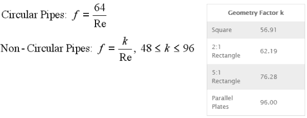
The pipe cross-section is also important, as deviations from circular cross-section will cause secondary flows that increase the head loss. Non-circular pipes and ducts are generally treated by using the hydraulic diameter.

Relative Roughness

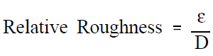
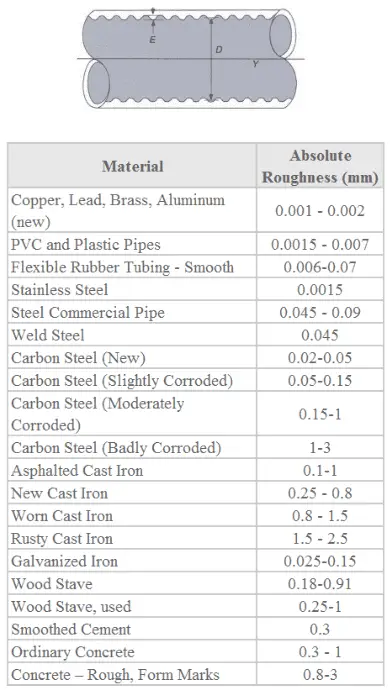
The quantity used to measure the roughness of the pipe’s inner surface is called the relative roughness, and it is equal to the average height of surface irregularities (ε) divided by the pipe diameter (D).

relative roughness - equation

,where both the average height surface irregularities and the pipe diameter are in millimeters.

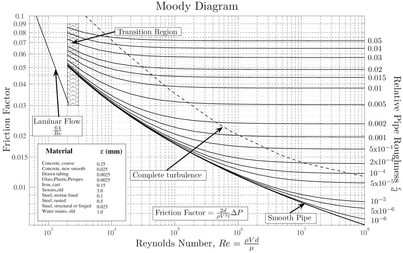
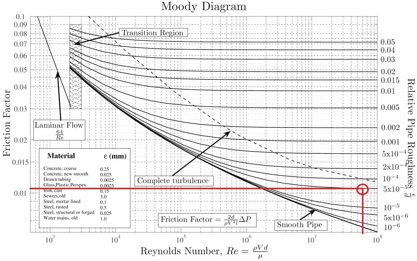
If we know the relative roughness of the pipe’s inner surface, then we can obtain the value of the friction factor from the Moody Chart.

The Moody chart (also known as the Moody diagram) is a graph in non-dimensional form that relates the Darcy friction factor, Reynolds number, and the relative roughness for fully developed flow in a circular pipe.

relative roughness - absolute roughness

 
Example: Moody Chart
Determine the friction factor (fD) for fluid flow in a pipe of 700mm in diameter that has the Reynolds number of 50 000 000 and an absolute roughness of 0.035 mm.

Solution:

The relative roughness is equal to ε = 0.035 / 700 = 5 x 10⁻⁵. Using the Moody Chart, a Reynolds number of 50 000 000 intersects the curve corresponding to a relative roughness of 5 x 10⁻⁵ at a friction factor of 0.011.

Moody chart, moody diagram
Example: Moody chart.
Source: Donebythesecondlaw at the English language Wikipedia, CC BY-SA 3.0, https://commons.wikimedia.org/w/index.php?curid=4681366

Darcy Friction Factor for various flow regime

The most common classification of flow regimes is according to the Reynolds number. The Reynolds number is a dimensionless number comprised of the physical characteristics of the flow and it determines whether the flow is laminar or turbulent. An increasing Reynolds number indicates an increasing turbulence of flow. As can be seen from the Moody chart, also Darcy friction factor is highly dependent on the flow regime (i.e. on the Reynolds number).

 
Darcy Friction Factor for Laminar Flow
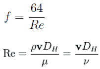
For practical purposes, if the Reynolds number is less than 2000, the flow is laminar. The accepted transition Reynolds number for flow in a circular pipe is Red,crit = 2300. For laminar flow, the head loss is proportional to velocity rather than velocity squared, thus the friction factor is inversely proportional to velocity.

The Darcy friction factor for laminar (slow) flows is a consequence of Poiseuille’s law that and it is given by following equations:

darcy friction factor for laminar flow

Darcy Friction Factor for Transitional Flow
At Reynolds numbers between about 2000 and 4000 the flow is unstable as a result of the onset of turbulence. These flows are sometimes referred to as transitional flows. The Darcy friction factor contains large uncertainties in this flow regime and is not well understood.
Darcy Friction Factor for Turbulent Flow
If the Reynolds number is greater than 3500, the flow is turbulent. Most fluid systems in nuclear facilities operate with turbulent flow. In this flow regime the resistance to flow follows the Darcy–Weisbach equation: it is proportional to the square of the mean flow velocity. The Darcy friction factor depends strongly on the relative roughness of the pipe’s inner surface.

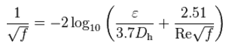
The most common method to determine a friction factor for turbulent flow is to use the Moody chart. The Moody chart (also known as the Moody diagram) is a log-log plot of the Colebrook correlation that relates the Darcy friction factor, Reynolds number, and the relative roughness for fully developed flow in a circular pipe. The Colebrook–White equation:

darcy friction factor for turbulent flow

which is also known as the Colebrook equation, expresses the Darcy friction factor f as a function of pipe relative roughness ε / Dh and Reynolds number.

In 1939, Colebrook found an implicit correlation for the friction factor in round pipes by fitting the data of experimental studies of turbulent flow in smooth and rough pipes.

For hydraulically smooth pipe and the turbulent flow (Re < 105) the friction factor can be approximated by Blasius formula:

 f = (100.Re)-¼

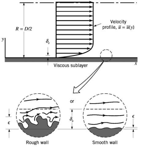
darcy friction factor - relative roughnessIt must be noted, at very large Reynolds numbers, the friction factor is independent of the Reynolds number. This is because the thickness of laminar sublayer (viscous sublayer) decreases with increasing Reynolds number. For very large Reynolds numbers the thickness of laminar sublayer is comparable to the surface roughness and it directly influences the flow. The laminar sublayer becomes so thin that the surface roughness protrudes into the flow. The frictional losses in this case are produced in the main flow primarily by the protruding roughness elements, and the contribution of the laminar sublayer is negligible.

Examples

 
Example: The head loss for one loop of primary piping
The primary circuit of typical PWRs is divided into 4 independent loops (piping diameter of about 700mm), each loop comprises a steam generator and one main coolant pump.

Assume that (this data do not represent any certain reactor design):

  • Inside the primary piping flows water at constant temperature of 290°C (⍴ ~ 720 kg/m3).
  • The kinematic viscosity of the water at 290°C is equal to 0.12 x 10⁻⁶ m2/s.
  • The primary piping flow velocity may be about 17 m/s.
  • The primary piping of one loop is about 20m long.
  • The Reynolds number inside the primary piping is equal to: ReD = 17 [m/s] x 0.7 [m] / 0.12×10⁻⁶ [m2/s] = 99 000 000
  • The Darcy friction factor is equal to fD = 0.01

Calculate the head loss for one loop of primary piping (without fitting, elbows, pumps etc.).

Solution:

Since we know all inputs of the Darcy-Weisbach equation, we can calculate the head loss directly:

Head loss form:

Δh = 0.01 x ½ x 1/9.81 x 20 x 172 / 0.7 = 4.2 m

Pressure loss form:

Δp = 0.01 x ½ x 720 x 20 x 172 / 0.7 = 29 725 Pa ≈ 0.03 MPa

Example: Change in head loss due to a decrease in viscosity.
In fully developed laminar flow in a circular pipe, the head loss is given by:
Major Head Loss - head formwhere:

darcy friction factor - laminar flow

Since the Reynolds number is inverse proportional to viscosity, then the resulting head loss becomes proportional to viscosity. Therefore, the head loss is reduced by half when the viscosity of the fluid is reduced by half, when the flow rate and thus the average velocity are held constant.

 
References:
Reactor Physics and Thermal Hydraulics:
  1. J. R. Lamarsh, Introduction to Nuclear Reactor Theory, 2nd ed., Addison-Wesley, Reading, MA (1983).
  2. J. R. Lamarsh, A. J. Baratta, Introduction to Nuclear Engineering, 3d ed., Prentice-Hall, 2001, ISBN: 0-201-82498-1.
  3. W. M. Stacey, Nuclear Reactor Physics, John Wiley & Sons, 2001, ISBN: 0- 471-39127-1.
  4. Glasstone, Sesonske. Nuclear Reactor Engineering: Reactor Systems Engineering, Springer; 4th edition, 1994, ISBN: 978-0412985317
  5. Todreas Neil E., Kazimi Mujid S. Nuclear Systems Volume I: Thermal Hydraulic Fundamentals, Second Edition. CRC Press; 2 edition, 2012, ISBN: 978-0415802871
  6. Zohuri B., McDaniel P. Thermodynamics in Nuclear Power Plant Systems. Springer; 2015, ISBN: 978-3-319-13419-2
  7. Moran Michal J., Shapiro Howard N. Fundamentals of Engineering Thermodynamics, Fifth Edition, John Wiley & Sons, 2006, ISBN: 978-0-470-03037-0
  8. Kleinstreuer C. Modern Fluid Dynamics. Springer, 2010, ISBN 978-1-4020-8670-0.
  9. U.S. Department of Energy, THERMODYNAMICS, HEAT TRANSFER, AND FLUID FLOW. DOE Fundamentals Handbook, Volume 1, 2 and 3. June 1992.
  10. White Frank M., Fluid Mechanics, McGraw-Hill Education, 7th edition, February, 2010, ISBN: 978-0077422417

See also:

Fluid Dynamics

We hope, this article, Major Head Loss – Friction Loss, helps you. If so, give us a like in the sidebar. Main purpose of this website is to help the public to learn some interesting and important information about thermal engineering.
What is Lift Force – Definition

In general, the lift is an upward-acting force on an aircraft wing or airfoil. There are several ways to explain how an airfoil generates lift. Lift Force

Bernoulli’s Equation

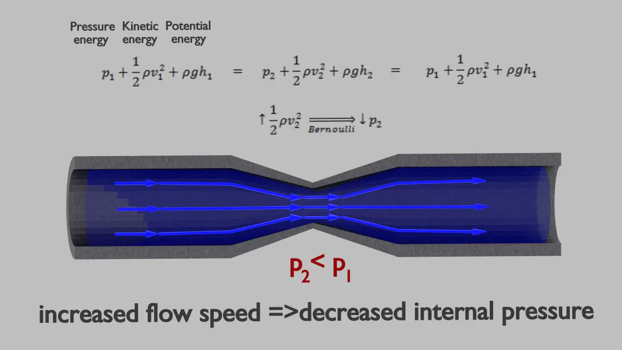
Bernoulli Equation; PrincipleThe Bernoulli’s equation can be considered to be a statement of the conservation of energy principle appropriate for flowing fluids. It is one of the most important/useful equations in fluid mechanics. It puts into a relation pressure and velocity in an inviscid incompressible flow. Bernoulli’s equation has some restrictions in its applicability, they summarized in following points:

  • steady flow system,
  • density is constant (which also means the fluid is incompressible),
  • no work is done on or by the fluid,
  • no heat is transferred to or from the fluid,
  • no change occurs in the internal energy,
  • the equation relates the states at two points along a single streamline (not conditions on two different streamlines)

Under these conditions, the general energy equation is simplified to:

Bernoulli Theorem - Equation
This equation is the most famous equation in fluid dynamics. The Bernoulli’s equation describes the qualitative behavior flowing fluid that is usually labeled with the term Bernoulli’s effect. This effect causes the lowering of fluid pressure in regions where the flow velocity is increased. This lowering of pressure in a constriction of a flow path may seem counterintuitive, but seems less so when you consider pressure to be energy density. In the high velocity flow through the constriction, kinetic energy must increase at the expense of pressure energy. The dimensions of terms in the equation are kinetic energy per unit volume.

Lift Force – Bernoulli’s Principle

Lift Force - Newtons Law
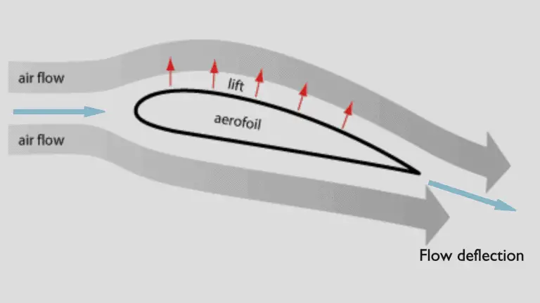
Newton’s third law states that the lift is caused by a flow deflection.

In general, the lift is an upward-acting force on an aircraft wing or airfoil. There are several ways to explain how an airfoil generates lift. Some theories are more complicated or more mathematically rigorous than others. Some theories have been shown to be incorrect. There are theories based on the Bernoulli’s principle and there are theories based on directly on the Newton’s third law.

The explanation based on the Newton’s third law states that the lift is caused by a flow deflection of the airstream behind the airfoil. The airfoil generates lift by exerting a downward force on the air as it flows past. According to Newton’s third law, the air must exert an upward force on the airfoil. This is very simple explanation.

Lift Force - Bernoulli Principle
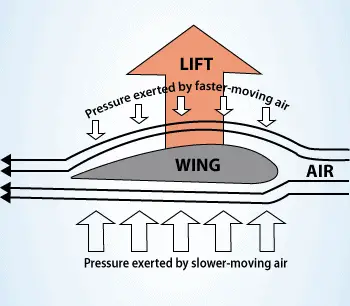
According to the Bernoulli’s principle, faster moving air exerts less pressure, and therefore the air must exert an upward force on the airfoil (as a result of a pressure difference).

Bernoulli’s principle combined with the continuity equation can be also used to determine the lift force on an airfoil, if the behaviour of the fluid flow in the vicinity of the foil is known. In this explanation the shape of an airfoil is crucial. The shape of an airfoil causes air to flow faster on top than on bottom. According to Bernoulli’s principle, faster moving air exerts less pressure, and therefore the air must exert an upward force on the airfoil (as a result of a pressure difference).

 
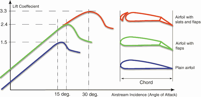
Lift coefficient as a function of Angle of Attack
Lift Coefficient - Flaps
Source: www.zenithair.net
Bernoulli’s principle requires airfoil to be of an asymmetrical shape. Its surface area must be greater on the top than on the bottom. As the air flows over the airfoil, it is displaced more by the top surface than the bottom. According to the continuity principle, this displacement must lead to an increase in flow velocity (resulting in a decrease in pressure). The flow velocity is increased some by the bottom airfoil surface, but considerably less than the flow on the top surface. The lift force of an airfoil, characterized by the lift coefficient, can be changed during the flight by changes in shape of an airfoil. The lift coefficient can thus be even doubled with relatively simple devices (flaps and slats) if used on the full span of the wing.
The use of Bernoulli’s principle may not be correct. The Bernoulli’s principle assumes incompressibility of the air, but in reality the air is easily compressible. But there are more limitations of explanations based on Bernoulli’s principle. There are two main popular explanations of lift:
  • Explanation based on downward deflection of the flow – Newton’s third law
  • Explanation based on changes in flow speed and pressure – Continuity principle and Bernoulli’s principle

Both explanations correctly identifies some aspects of the lift forces but leaves other important aspects of the phenomenon unexplained. A more comprehensive explanation involves both changes in flow speed and downward deflection and requires looking at the flow in more detail.

See more: Doug McLean, Understanding Aerodynamics: Arguing from the Real Physics. John Wiley & Sons Ltd. 2013. ISBN:  978-1119967514

 
References:
Reactor Physics and Thermal Hydraulics:
  1. J. R. Lamarsh, Introduction to Nuclear Reactor Theory, 2nd ed., Addison-Wesley, Reading, MA (1983).
  2. J. R. Lamarsh, A. J. Baratta, Introduction to Nuclear Engineering, 3d ed., Prentice-Hall, 2001, ISBN: 0-201-82498-1.
  3. W. M. Stacey, Nuclear Reactor Physics, John Wiley & Sons, 2001, ISBN: 0- 471-39127-1.
  4. Glasstone, Sesonske. Nuclear Reactor Engineering: Reactor Systems Engineering, Springer; 4th edition, 1994, ISBN: 978-0412985317
  5. Todreas Neil E., Kazimi Mujid S. Nuclear Systems Volume I: Thermal Hydraulic Fundamentals, Second Edition. CRC Press; 2 edition, 2012, ISBN: 978-0415802871
  6. Zohuri B., McDaniel P. Thermodynamics in Nuclear Power Plant Systems. Springer; 2015, ISBN: 978-3-319-13419-2
  7. Moran Michal J., Shapiro Howard N. Fundamentals of Engineering Thermodynamics, Fifth Edition, John Wiley & Sons, 2006, ISBN: 978-0-470-03037-0
  8. Kleinstreuer C. Modern Fluid Dynamics. Springer, 2010, ISBN 978-1-4020-8670-0.
  9. U.S. Department of Energy, THERMODYNAMICS, HEAT TRANSFER, AND FLUID FLOW. DOE Fundamentals Handbook, Volume 1, 2 and 3. June 1992.

See also:

Bernoulli’s Principle

We hope, this article, Lift Force, helps you. If so, give us a like in the sidebar. Main purpose of this website is to help the public to learn some interesting and important information about thermal engineering.