To characterize the region with entrance the hydrodynamic entrance length must be introduced. The hydrodynamic entrance length must be checked in all calculations. Thermal Engineering
Hydrodynamic Entrance Length
Source: White Frank M., Fluid Mechanics, McGraw-Hill Education, 7th edition, February, 2010, ISBN: 978-0077422417
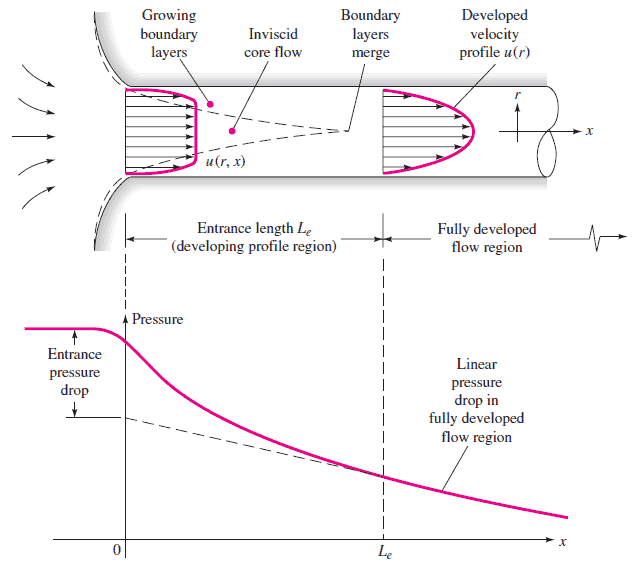
For internal flow regime an entrance region is typical. In this region a nearly inviscid upstream flow converges and enters the tube. To characterize this region the hydrodynamic entrance length is introduced and is approximately equal to:
The maximum hydrodynamic entrance length, at ReD,crit = 2300 (laminar flow), is Le = 138d, where D is the diameter of the pipe. This is the longest development length possible. In turbulent flow, the boundary layers grow faster, and Le is relatively shorter. For any given problem, Le / D has to be checked to see if Le is negligible when compared to the pipe length. At a finite distance from the entrance, the entrance effects may be neglected, because the boundary layers merge and the inviscid core disappears. The tube flow is then fully developed.
References:
Reactor Physics and Thermal Hydraulics:
J. R. Lamarsh, Introduction to Nuclear Reactor Theory, 2nd ed., Addison-Wesley, Reading, MA (1983).
J. R. Lamarsh, A. J. Baratta, Introduction to Nuclear Engineering, 3d ed., Prentice-Hall, 2001, ISBN: 0-201-82498-1.
W. M. Stacey, Nuclear Reactor Physics, John Wiley & Sons, 2001, ISBN: 0- 471-39127-1.
Todreas Neil E., Kazimi Mujid S. Nuclear Systems Volume I: Thermal Hydraulic Fundamentals, Second Edition. CRC Press; 2 edition, 2012, ISBN: 978-0415802871
Zohuri B., McDaniel P. Thermodynamics in Nuclear Power Plant Systems. Springer; 2015, ISBN: 978-3-319-13419-2
Moran Michal J., Shapiro Howard N. Fundamentals of Engineering Thermodynamics, Fifth Edition, John Wiley & Sons, 2006, ISBN: 978-0-470-03037-0
Kleinstreuer C. Modern Fluid Dynamics. Springer, 2010, ISBN 978-1-4020-8670-0.
U.S. Department of Energy, THERMODYNAMICS, HEAT TRANSFER, AND FLUID FLOW. DOE Fundamentals Handbook, Volume 1, 2 and 3. June 1992.
White Frank M., Fluid Mechanics, McGraw-Hill Education, 7th edition, February, 2010, ISBN: 978-0077422417
See also:
Internal Flow
We hope, this article, Hydrodynamic Entrance Length, helps you. If so, give us a like in the sidebar. Main purpose of this website is to help the public to learn some interesting and important information about thermal engineering.
The external flow is such a flow in which boundary layers develop freely, without constraints imposed by adjacent surfaces. External Flow
Classification of Flow Regimes
From a practical engineering point of view the flow regime can be categorized according to several criteria.
All fluid flow is classified into one of two broad categories or regimes. These two flow regimes are:
Single-phase Fluid Flow
Multi-phase Fluid Flow (or Two-phase Fluid Flow)
This is a basic classification. All of the fluid flow equations (e.g. Bernoulli’s Equation) and relationships that were discussed in this section (Fluid Dynamics) were derived for the flow of a single phase of fluid whether liquid or vapor. Solution of multi-phase fluid flow is very complex and difficult and therefore it is usually in advanced courses of fluid dynamics.
Another usually more common classification of flow regimes is according to the shape and type of streamlines. All fluid flow is classified into one of two broad categories. The fluid flow can be either laminar or turbulent and therefore these two categories are:
Laminar Flow
Turbulent Flow
Laminar flow is characterized by smooth or in regular paths of particles of the fluid. Therefore the laminar flow is also referred to as streamline or viscous flow. In contrast to laminar flow, turbulent flow is characterized by the irregular movement of particles of the fluid. The turbulent fluid does not flow in parallel layers, the lateral mixing is very high, and there is a disruption between the layers. Most industrial flows, especially those in nuclear engineering are turbulent.
The flow regime can be also classified according to the geometry of a conduit or flow area. From this point of view, we distinguish:
Internal Flow
External Flow
Internal flow is a flow for which the fluid is confined by a surface. Detailed knowledge of behaviour of internal flow regimes is of importance in engineering, because circular pipes can withstand high pressures and hence are used to convey liquids. On the other hand, external flow is such a flow in which boundary layers develop freely, without constraints imposed by adjacent surfaces. Detailed knowledge of behaviour of external flow regimes is of importance especially in aeronautics and aerodynamics.
External Flow
In fluid dynamics, external flow is such a flow in which boundary layers develop freely, without constraints imposed by adjacent surfaces. In comparison to internal flow, entrance flows and external flows feature highly viscous effects confined to rapidly growing “boundary layers” in the entrance region, or to thin shear layers along the solid surface. Accordingly, there will always exist a region of the flow outside the boundary layer. In this region velocity, temperature, and/or concentration does not change in and their gradients may be neglected.
This effect causes the boundary layer to be expanding and the boundary-layer thickness relates to the square root of the fluid’s kinematic viscosity.
This is demonstrated on the following picture. Far from the body the flow is nearly inviscid, it can be defined as the flow of a fluid around a body that is completely submerged in it.
Fluid Flow over a Flat Plate
In general, when a fluid flows over a stationary surface, e.g. the flat plate, the bed of a river, or the wall of a pipe, the fluid touching the surface is brought to rest by the shear stress to at the wall. The region in which flow adjusts from zero velocity at the wall to a maximum in the main stream of the flow is termed the boundary layer. The concept of boundary layers is of importance in all of viscous fluid dynamics and also in the theory of heat transfer.
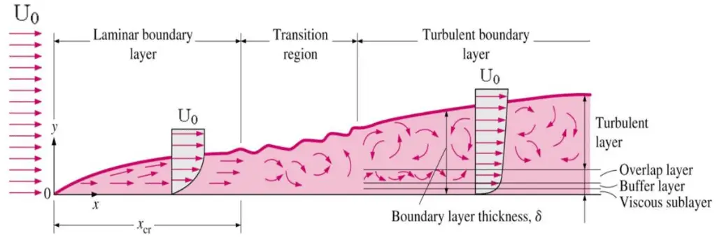
Basic characteristics of all laminar and turbulent boundary layers are shown in the developing flow over a flat plate. The stages of the formation of the boundary layer are shown in the figure below:
Boundary layers may be either laminar, or turbulent depending on the value of the Reynolds number.
See also: Boundary Layer
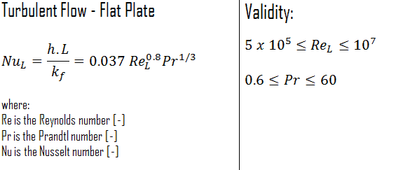
Nusselt Number
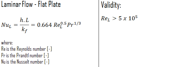
The average Nusselt numberover the entire plate is determined by:
This relation gives the average heat transfer coefficient for the entire plate only when the flow is turbulentover the entire plate, or when the laminar flow region of the plate is too small relative to the turbulent flow region.
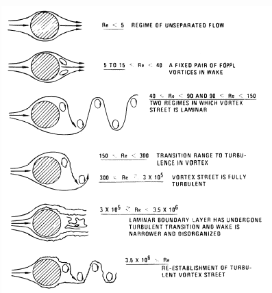
Tube in crossflow
Source: Blevins, R. D. (1990), Flow Induced Vibration, 2nd Edn., Van Nostrand Reinhold Co.
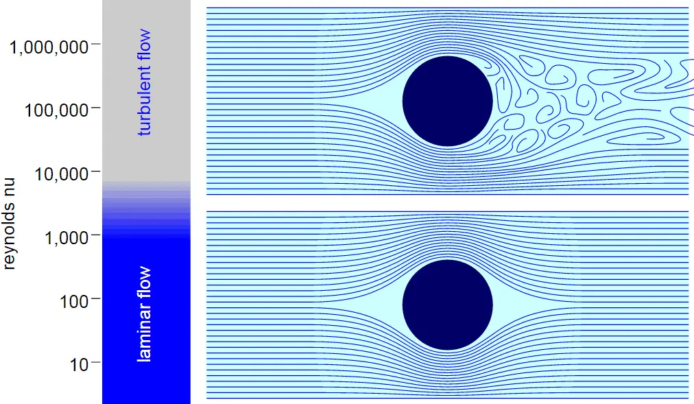
The crossflow of tubes or cylinders shows many flow regimes, that are dependent on the Reynolds number.
ReD < 5. At Reynolds numbers below 1 no separation occurs.
5 ≤ ReD ≤ 45. In this Reynolds number range the flow separates from the rear side of the tube and a symmetric pair of vortices is formed in the near wake.
40 ≤ ReD ≤ 150. In this Reynolds number range the wake becomes unstable and vortex shedding is initiated.
150 < ReD < 300. In this Reynolds number range is the flow transitional and gradually becomes turbulent as the Reynolds number is increased.
300 < ReD < 1.5·105. This region is called subcritical. The laminar boundary layer separates at about 80 degrees downstream of the front stagnation point and the vortex shedding is strong and periodic.
2·105 < ReD < 3.5·106. Three-dimensional effects disrupt the regular shedding process and the spectrum of shedding frequencies is broadened. With a further increase of ReD, the flow enters the critical regime.
ReD > 3.5·106. This regime is called supercritical. In this regime a regular vortex shedding is re-established with a turbulent boundary layer on the tube surface.
References:
Reactor Physics and Thermal Hydraulics:
J. R. Lamarsh, Introduction to Nuclear Reactor Theory, 2nd ed., Addison-Wesley, Reading, MA (1983).
J. R. Lamarsh, A. J. Baratta, Introduction to Nuclear Engineering, 3d ed., Prentice-Hall, 2001, ISBN: 0-201-82498-1.
W. M. Stacey, Nuclear Reactor Physics, John Wiley & Sons, 2001, ISBN: 0- 471-39127-1.
Todreas Neil E., Kazimi Mujid S. Nuclear Systems Volume I: Thermal Hydraulic Fundamentals, Second Edition. CRC Press; 2 edition, 2012, ISBN: 978-0415802871
Zohuri B., McDaniel P. Thermodynamics in Nuclear Power Plant Systems. Springer; 2015, ISBN: 978-3-319-13419-2
Moran Michal J., Shapiro Howard N. Fundamentals of Engineering Thermodynamics, Fifth Edition, John Wiley & Sons, 2006, ISBN: 978-0-470-03037-0
Kleinstreuer C. Modern Fluid Dynamics. Springer, 2010, ISBN 978-1-4020-8670-0.
U.S. Department of Energy, THERMODYNAMICS, HEAT TRANSFER, AND FLUID FLOW. DOE Fundamentals Handbook, Volume 1, 2 and 3. June 1992.
White Frank M., Fluid Mechanics, McGraw-Hill Education, 7th edition, February, 2010, ISBN: 978-0077422417
See also:
Flow Regime
We hope, this article, External Flow, helps you. If so, give us a like in the sidebar. Main purpose of this website is to help the public to learn some interesting and important information about thermal engineering.
The concept of boundary layers is of importance in all of fluid dynamics. Basic characteristics of all laminar and turbulent boundary layers are shown here. Thermal Engineering
Boundary Layer
In general, when a fluid flows over a stationary surface, e.g. the flat plate, the bed of a river, or the wall of a pipe, the fluid touching the surface is brought to rest by the shear stress to at the wall. The region in which flow adjusts from zero velocity at the wall to a maximum in the main stream of the flow is termed the boundary layer. The concept of boundary layers is of importance in all of viscous fluid dynamics and also in the theory of heat transfer.
Basic characteristics of all laminar and turbulent boundary layers are shown in the developing flow over a flat plate. The stages of the formation of the boundary layer are shown in the figure below:
Boundary layers may be either laminar, or turbulent depending on the value of the Reynolds number.
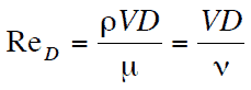
The Reynolds number is the ratio of inertia forces to viscous forces and is a convenient parameter for predicting if a flow condition will be laminar or turbulent. It is defined as
in which V is the mean flow velocity, D a characteristic linear dimension, ρ fluid density, μ dynamic viscosity, and ν kinematic viscosity.
For lower Reynolds numbers, the boundary layer is laminar and the streamwise velocity changes uniformly as one moves away from the wall, as shown on the left side of the figure. As the Reynolds number increases (with x) the flow becomes unstable and finally for higher Reynolds numbers, the boundary layer is turbulent and the streamwise velocity is characterized by unsteady (changing with time) swirling flows inside the boundary layer.
Transition from laminar to turbulent boundary layer occurs when Reynolds number at x exceeds Rex ~ 500,000. Transition may occur earlier, but it is dependent especially on the surface roughness. The turbulent boundary layer thickens more rapidly than the laminar boundary layer as a result of increased shear stress at the body surface.
The external flow reacts to the edge of the boundary layer just as it would to the physical surface of an object. So the boundary layer gives any object an “effective” shape which is usually slightly different from the physical shape. We define the thickness of the boundary layer as the distance from the wall to the point where the velocity is 99% of the “free stream” velocity.
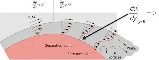
To make things more confusing, the boundary layer may lift off or “separate” from the body and create an effective shape much different from the physical shape. This happens because the flow in the boundary has very low energy (relative to the free stream) and is more easily driven by changes in pressure.
Special reference: Schlichting Herrmann, Gersten Klaus. Boundary-Layer Theory, Springer-Verlag Berlin Heidelberg, 2000, ISBN: 978-3-540-66270-9
Example: Transition Layer
A long thin flat plate is placed parallel to a 1 m/s stream of water at 20°C. Assume that kinematic viscosity of water at 20°C is equal to 1×10⁻⁶ m2/s.
At what distance x from the leading edge will be the transition from laminar to turbulent boundary layer (i.e. find Rex ~ 500,000).
Solution:
In order to locate the transition from laminar to turbulent boundary layer, we have to find x at which Rex ~ 500,000.
x = 500 000 x 1×10-6 [m2/s] / 1 [m/s] = 0.5 m
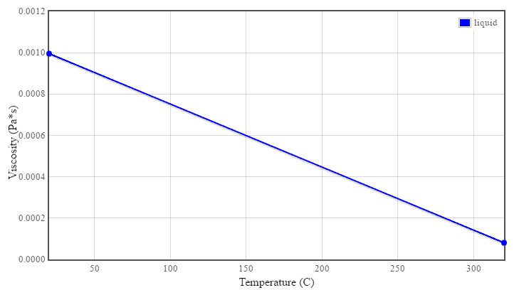
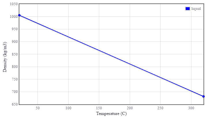
Charts: Viscosity and Density of Water (16MPa)
Boundary Layer Thickness
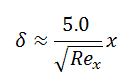
We define the thickness of the boundary layer as the distance from the wall to the point where the velocity is 99% of the “free stream” velocity. For laminar boundary layers over a flat plate, the Blasius solution of the flow governing equations gives:
where Rex is the Reynolds number based on the length of the plate.
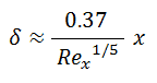
For a turbulent flow the boundary layer thickness is given by:
This equation was derived with several assumptions. The turbulent boundary layer thickness formula assumes that the flow is turbulent right from the start of the boundary layer.
Example: Boundary Layer Thickness
Consider a water flow (20°C) at v = 0.1 m/s past a flat plate 1 m long. Compute the boundary layer thickness in the middle of the plate. Assume that kinematic viscosity of water at 20°C is equal to 1×10⁻⁶ m2/s.
The Reynolds number for the middle of the plate is equal to:
This satisfies the laminar conditions. The boundary layer thickness is therefore equal to:
δ ≈ 5.0 x 0.5 / (50 000)½ = 0.011 m
Thermal Boundary Layer
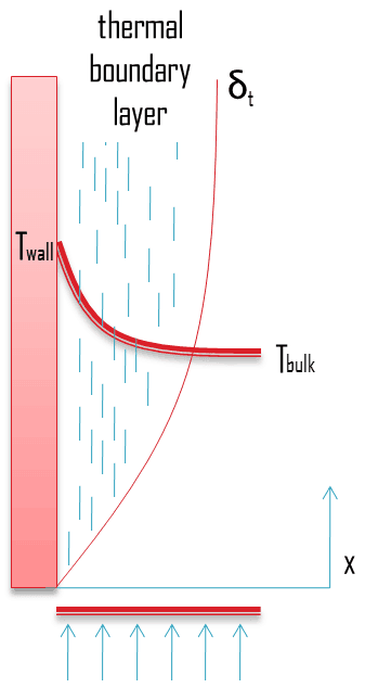
Similarly as a velocity boundary layer develops when there is fluid flow over a surface, a thermal boundary layer must develop if the bulk temperature and surface temperature differ. Consider flow over an isothermal flat plate at a constant temperature of Twall. At the leading edge the temperature profile is uniform with Tbulk. Fluid particles that come into contact with the plate achieve thermal equilibrium at the plate’s surface temperature. At this point, energy flow occurs at the surface purely by conduction. These particles exchange energy with those in the adjoining fluid layer (by conduction and diffusion), and temperature gradients develop in the fluid. The region of the fluid in which these temperature gradients exist is the thermal boundary layer. Its thickness, δt, is typically defined as the distance from the body at which the temperature is 99% of the temperature found from an inviscid solution. With increasing distance from the leading edge, the effects of heat transfer penetrate farther into the stream and the thermal boundary layer grows.
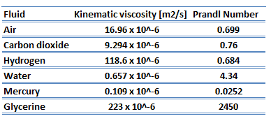
The ratio of these two thicknesses (velocity and thermal boundary layers) is governed by the Prandtl number, which is defined as the ratio of momentum diffusivity to thermal diffusivity. A Prandtl number of unity indicates that momentum and thermal diffusivity are comparable, and velocity and thermal boundary layers almost coincide with each other. If the Prandtl number is less than 1, which is the case for air at standard conditions, the thermal boundary layer is thicker than the velocity boundary layer. If the Prandtl number is greater than 1, the thermal boundary layer is thinner than the velocity boundary layer. Air at room temperature has a Prandtl number of 0.71 and for water at 18°C it is around 7.56, which means that the thermal diffusivity is more dominant for air than for water.
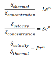
Similarly as for Prandtl Number, the Lewis number physically relates the relative thickness of the thermal layer and mass-transfer (concentration) boundary layer. The Schmidt number physically relates the relative thickness of the velocity boundary layer and mass-transfer (concentration) boundary layer.
where n = 1/3 for most applications in all three relations. These relations, in general, are applicable only for laminar flow and are not applicable to turbulent boundary layers since turbulent mixing in this case may dominate the diffusion processes.
References:
Reactor Physics and Thermal Hydraulics:
J. R. Lamarsh, Introduction to Nuclear Reactor Theory, 2nd ed., Addison-Wesley, Reading, MA (1983).
J. R. Lamarsh, A. J. Baratta, Introduction to Nuclear Engineering, 3d ed., Prentice-Hall, 2001, ISBN: 0-201-82498-1.
W. M. Stacey, Nuclear Reactor Physics, John Wiley & Sons, 2001, ISBN: 0- 471-39127-1.
Todreas Neil E., Kazimi Mujid S. Nuclear Systems Volume I: Thermal Hydraulic Fundamentals, Second Edition. CRC Press; 2 edition, 2012, ISBN: 978-0415802871
Zohuri B., McDaniel P. Thermodynamics in Nuclear Power Plant Systems. Springer; 2015, ISBN: 978-3-319-13419-2
Moran Michal J., Shapiro Howard N. Fundamentals of Engineering Thermodynamics, Fifth Edition, John Wiley & Sons, 2006, ISBN: 978-0-470-03037-0
Kleinstreuer C. Modern Fluid Dynamics. Springer, 2010, ISBN 978-1-4020-8670-0.
U.S. Department of Energy, THERMODYNAMICS, HEAT TRANSFER, AND FLUID FLOW. DOE Fundamentals Handbook, Volume 1, 2 and 3. June 1992.
White Frank M., Fluid Mechanics, McGraw-Hill Education, 7th edition, February, 2010, ISBN: 978-0077422417
See also:
Fluid Dynamics
We hope, this article, Boundary Layer, helps you. If so, give us a like in the sidebar. Main purpose of this website is to help the public to learn some interesting and important information about thermal engineering.
We define the thickness of the boundary layer as the distance from the wall to the point where the velocity is 99% of the “free stream” velocity. Boundary Layer. Thermal Engineering
Boundary Layer Thickness
We define the thickness of the boundary layer as the distance from the wall to the point where the velocity is 99% of the “free stream” velocity. For laminar boundary layers over a flat plate, the Blasius solution of the flow governing equations gives:
where Rex is the Reynolds number based on the length of the plate.
For a turbulent flow the boundary layer thickness is given by:
This equation was derived with several assumptions. The turbulent boundary layer thickness formula assumes that the flow is turbulent right from the start of the boundary layer.
Example: Boundary Layer Thickness
Consider a water flow (20°C) at v = 0.1 m/s past a flat plate 1 m long. Compute the boundary layer thickness in the middle of the plate. Assume that kinematic viscosity of water at 20°C is equal to 1×10⁻⁶ m2/s.
The Reynolds number for the middle of the plate is equal to:
This satisfies the laminar conditions. The boundary layer thickness is therefore equal to:
δ ≈ 5.0 x 0.5 / (50 000)½ = 0.011 m
Example: Transition Layer
A long thin flat plate is placed parallel to a 1 m/s stream of water at 20°C. Assume that kinematic viscosity of water at 20°C is equal to 1×10⁻⁶ m2/s.
At what distance x from the leading edge will be the transition from laminar to turbulent boundary layer (i.e. find Rex ~ 500,000).
Solution:
In order to locate the transition from laminar to turbulent boundary layer, we have to find x at which Rex ~ 500,000.
x = 500 000 x 1×10-6 [m2/s] / 1 [m/s] = 0.5 m
References:
Reactor Physics and Thermal Hydraulics:
J. R. Lamarsh, Introduction to Nuclear Reactor Theory, 2nd ed., Addison-Wesley, Reading, MA (1983).
J. R. Lamarsh, A. J. Baratta, Introduction to Nuclear Engineering, 3d ed., Prentice-Hall, 2001, ISBN: 0-201-82498-1.
W. M. Stacey, Nuclear Reactor Physics, John Wiley & Sons, 2001, ISBN: 0- 471-39127-1.
Todreas Neil E., Kazimi Mujid S. Nuclear Systems Volume I: Thermal Hydraulic Fundamentals, Second Edition. CRC Press; 2 edition, 2012, ISBN: 978-0415802871
Zohuri B., McDaniel P. Thermodynamics in Nuclear Power Plant Systems. Springer; 2015, ISBN: 978-3-319-13419-2
Moran Michal J., Shapiro Howard N. Fundamentals of Engineering Thermodynamics, Fifth Edition, John Wiley & Sons, 2006, ISBN: 978-0-470-03037-0
Kleinstreuer C. Modern Fluid Dynamics. Springer, 2010, ISBN 978-1-4020-8670-0.
U.S. Department of Energy, THERMODYNAMICS, HEAT TRANSFER, AND FLUID FLOW. DOE Fundamentals Handbook, Volume 1, 2 and 3. June 1992.
White Frank M., Fluid Mechanics, McGraw-Hill Education, 7th edition, February, 2010, ISBN: 978-0077422417
See also:
Boundary Layer
We hope, this article, Boundary Layer Thickness, helps you. If so, give us a like in the sidebar. Main purpose of this website is to help the public to learn some interesting and important information about thermal engineering.
The Reynolds number is the ratio of inertial forces to viscous forces and is a convenient parameter for predicting if a flow condition will be laminar or turbulent. Thermal Engineering
Reynolds Number
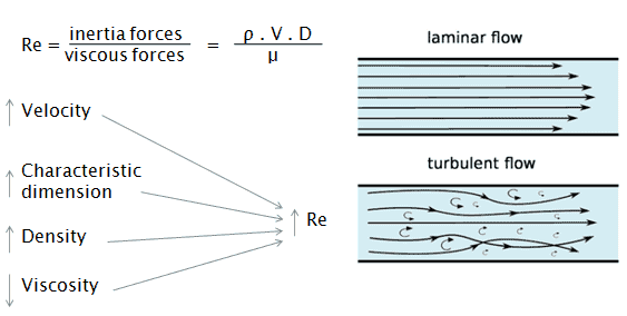
The Reynolds number is the ratio of inertial forces to viscous forces and is a convenient parameter for predicting if a flow condition will be laminar or turbulent. It can be interpreted that when the viscous forces are dominant (slow flow, low Re) they are sufficient enough to keep all the fluid particles in line, then the flow is laminar. Even very low Re indicates viscous creeping motion, where inertia effects are negligible. When the inertial forces dominate over the viscous forces (when the fluid is flowing faster and Re is larger) then the flow is turbulent.
It is a dimensionless number comprised of the physical characteristics of the flow. An increasing Reynolds number indicates an increasing turbulence of flow.
It is defined as:
where:
V is the flow velocity,
D is a characteristic linear dimension, (travelled length of the fluid; hydraulic diameter etc.)
ρ fluid density (kg/m3),
μ dynamic viscosity (Pa.s),
ν kinematic viscosity (m2/s); ν = μ / ρ.
Charts: Viscosity and Density of Water (16MPa)
[/su_accordion]
Laminar vs. Turbulent Flow
Laminar flow:
Re < 2000
‘low’ velocity
Fluid particles move in straight lines
Layers of water flow over one another at different speeds with virtually no mixing between layers.
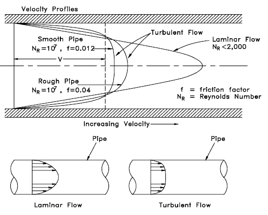
The flow velocity profile for laminar flow in circular pipes is parabolic in shape, with a maximum flow in the center of the pipe and a minimum flow at the pipe walls.
The average flow velocity is approximately one half of the maximum velocity.
Simple mathematical analysis is possible.
Rare in practice in water systems.
Turbulent Flow:
Re > 4000
‘high’ velocity
The flow is characterized by the irregular movement of particles of the fluid.
Average motion is in the direction of the flow
The flow velocity profile for turbulent flow is fairly flat across the center section of a pipe and drops rapidly extremely close to the walls.
The average flow velocity is approximately equal to the velocity at the center of the pipe.
Mathematical analysis is very difficult.
Most common type of flow.
Classification of Flow Regimes
From a practical engineering point of view the flow regime can be categorized according to several criteria.
All fluid flow is classified into one of two broad categories or regimes. These two flow regimes are:
Single-phase Fluid Flow
Multi-phase Fluid Flow (or Two-phase Fluid Flow)
This is a basic classification. All of the fluid flow equations (e.g. Bernoulli’s Equation) and relationships that were discussed in this section (Fluid Dynamics) were derived for the flow of a single phase of fluid whether liquid or vapor. Solution of multi-phase fluid flow is very complex and difficult and therefore it is usually in advanced courses of fluid dynamics.
Another usually more common classification of flow regimes is according to the shape and type of streamlines. All fluid flow is classified into one of two broad categories. The fluid flow can be either laminar or turbulent and therefore these two categories are:
Laminar Flow
Turbulent Flow
Laminar flow is characterized by smooth or in regular paths of particles of the fluid. Therefore the laminar flow is also referred to as streamline or viscous flow. In contrast to laminar flow, turbulent flow is characterized by the irregular movement of particles of the fluid. The turbulent fluid does not flow in parallel layers, the lateral mixing is very high, and there is a disruption between the layers. Most industrial flows, especially those in nuclear engineering are turbulent.
The flow regime can be also classified according to the geometry of a conduit or flow area. From this point of view, we distinguish:
Internal Flow
External Flow
Internal flow is a flow for which the fluid is confined by a surface. Detailed knowledge of behaviour of internal flow regimes is of importance in engineering, because circular pipes can withstand high pressures and hence are used to convey liquids. On the other hand, external flow is such a flow in which boundary layers develop freely, without constraints imposed by adjacent surfaces. Detailed knowledge of behaviour of external flow regimes is of importance especially in aeronautics and aerodynamics.
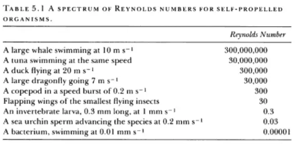
Table from Life in Moving Fluids
Table from Life in Moving Fluids: The Physical Biology of Flow by Steven Vogel
Reynolds Number Regimes
Laminar flow. For practical purposes, if the Reynolds number is less than 2000, the flow is laminar. The accepted transition Reynolds number for flow in a circular pipe is Red,crit = 2300.
Transitional flow. At Reynolds numbers between about 2000 and 4000 the flow is unstable as a result of the onset of turbulence. These flows are sometimes referred to as transitional flows.
Turbulent flow. If the Reynolds number is greater than 3500, the flow is turbulent. Most fluid systems in nuclear facilities operate with turbulent flow.
Reynolds Number and Internal Flow
Source: White Frank M., Fluid Mechanics, McGraw-Hill Education, 7th edition, February, 2010, ISBN: 978-0077422417
The internal flow (e.g. flow in a pipe) configuration is a convenient geometry for heating and cooling fluids used in energy conversion technologies such as nuclear power plants.
In general, this flow regime is of importance in engineering, because circular pipes can withstand high pressures and hence are used to convey liquids. Non-circular ducts are used to transport low-pressure gases, such as air in cooling and heating systems.
For internal flow regime an entrance region is typical. In this region a nearly inviscid upstream flow converges and enters the tube. To characterize this region the hydrodynamic entrance length is introduced and is approximately equal to:
The maximum hydrodynamic entrance length, at ReD,crit = 2300 (laminar flow), is Le = 138d, where D is the diameter of the pipe. This is the longest development length possible. In turbulent flow, the boundary layers grow faster, and Le is relatively shorter. For any given problem, Le / D has to be checked to see if Le is negligible when compared to the pipe length. At a finite distance from the entrance, the entrance effects may be neglected, because the boundary layers merge and the inviscid core disappears. The tube flow is then fully developed.
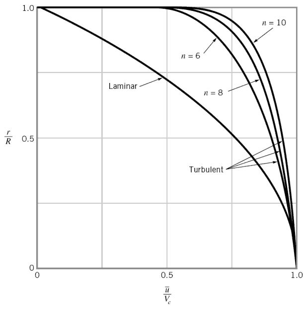
The velocity profile in turbulent flow is flatter in the central part of the pipe (i.e. in the turbulent core) than in laminar flow. The flow velocity drops rapidly extremely close to the walls. This is due to the diffusivity of the turbulent flow.
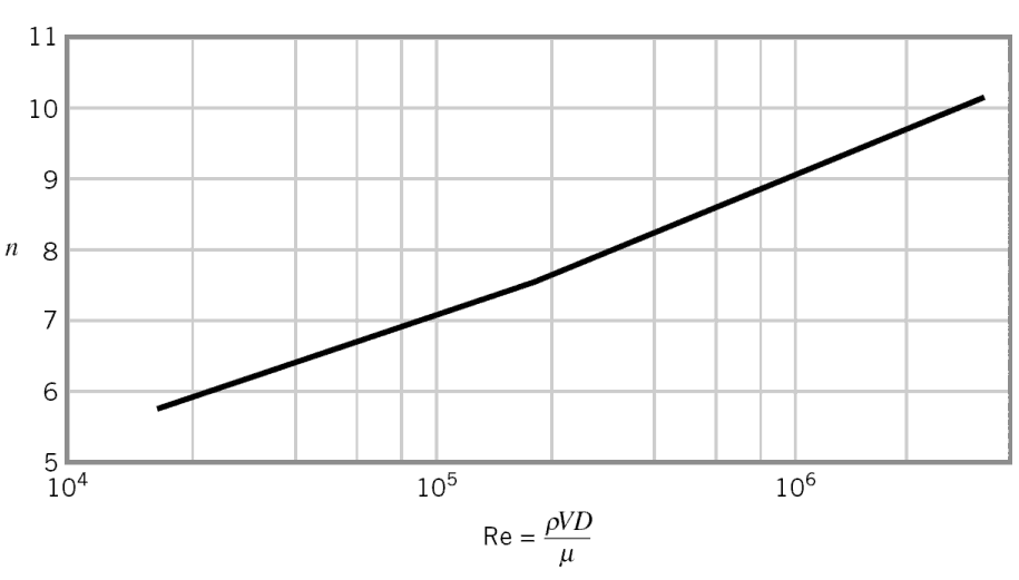
In case of turbulent pipe flow, there are many empirical velocity profiles. The simplest and the best known is the power-law velocity profile:
where the exponent n is a constant whose value depends on the Reynolds number. This dependency is empirical and it is shown at the picture. In short, the value n increases with increasing Reynolds number. The one-seventh power-law velocity profile approximates many industrial flows.
Turbulent flow – profiles
Hydraulic Diameter
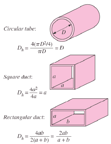
Since the characteristic dimension of a circular pipe is an ordinary diameter D and especially reactors contains non-circular channels, the characteristic dimension must be generalized.
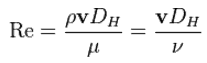
For these purposes the Reynolds number is defined as:
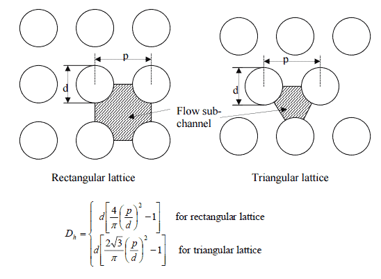
The hydraulic diameter, Dh, is a commonly used term when handling flow in non-circular tubes and channels. The hydraulic diameter transforms non-circular ducts into pipes of equivalent diameter. Using this term, one can calculate many things in the same way as for a round tube. In this equation A is the cross-sectional area, and P is the wetted perimeter of the cross-section. The wetted perimeter for a channel is the total perimeter of all channel walls that are in contact with the flow.
Example: Reynolds number for a primary piping and a fuel bundle
It is an illustrative example, following data do not correspond to any reactor design.
Pressurized water reactors are cooled and moderated by high-pressure liquid water (e.g. 16MPa). At this pressure water boils at approximately 350°C (662°F). Inlet temperature of the water is about 290°C (⍴ ~ 720 kg/m3). The water (coolant) is heated in the reactor core to approximately 325°C (⍴ ~ 654 kg/m3) as the water flows through the core.
The hydraulic diameter of fuel rods bundle.
The primary circuit of typical PWRs is divided into 4 independent loops (piping diameter ~ 700mm), each loop comprises a steam generatorand one main coolant pump. Inside the reactor pressure vessel (RPV), the coolant first flows down outside the reactor core (through the downcomer). From the bottom of the pressure vessel, the flow is reversed up through the core, where the coolant temperature increases as it passes through the fuel rods and the assemblies formed by them.
Assume:
the primary piping flow velocity is constant and equal to 17 m/s,
the core flow velocity is constant and equal to 5 m/s,
the hydraulic diameter of the fuel channel, Dh, is equal to 1 cm
the kinematic viscosity of the water at 290°C is equal to 0.12 x 10⁻⁶ m2/s
This also fully satisfies the turbulent conditions.
Reynolds Number and External Flow
The Reynolds number describes naturally the external flow as well. In general, when a fluid flows over a stationary surface, e.g. the flat plate, the bed of a river, or the wall of a pipe, the fluid touching the surface is brought to rest by the shear stress to at the wall. The region in which flow adjusts from zero velocity at the wall to a maximum in the main stream of the flow is termed the boundary layer.
Basic characteristics of all laminar and turbulent boundary layers are shown in the developing flow over a flat plate. The stages of the formation of the boundary layer are shown in the figure below:
Boundary layers may be either laminar, or turbulent depending on the value of the Reynolds number.
Also here the Reynolds number represents the ratio of inertia forces to viscous forces and is a convenient parameter for predicting if a flow condition will be laminar or turbulent. It is defined as:
in which V is the mean flow velocity, D a characteristic linear dimension, ρ fluid density, μ dynamic viscosity, and ν kinematic viscosity.
For lower Reynolds numbers, the boundary layer is laminar and the streamwise velocity changes uniformly as one moves away from the wall, as shown on the left side of the figure. As the Reynolds number increases (with x) the flow becomes unstable and finally for higher Reynolds numbers, the boundary layer is turbulent and the streamwise velocity is characterized by unsteady (changing with time) swirling flows inside the boundary layer.
Transition from laminar to turbulent boundary layer occurs when Reynolds number at x exceeds Rex ~ 500,000. Transition may occur earlier, but it is dependent especially on the surface roughness. The turbulent boundary layer thickens more rapidly than the laminar boundary layer as a result of increased shear stress at the body surface.
The external flow reacts to the edge of the boundary layer just as it would to the physical surface of an object. So the boundary layer gives any object an “effective” shape which is usually slightly different from the physical shape. We define the thickness of the boundary layer as the distance from the wall to the point where the velocity is 99% of the “free stream” velocity.
To make things more confusing, the boundary layer may lift off or “separate” from the body and create an effective shape much different from the physical shape. This happens because the flow in the boundary has very low energy (relative to the free stream) and is more easily driven by changes in pressure.
Special reference: Schlichting Herrmann, Gersten Klaus. Boundary-Layer Theory, Springer-Verlag Berlin Heidelberg, 2000, ISBN: 978-3-540-66270-9
Example: Transition Layer
A long thin flat plate is placed parallel to a 1 m/s stream of water at 20°C. Assume that kinematic viscosity of water at 20°C is equal to 1×10⁻⁶ m2/s.
At what distance x from the leading edge will be the transition from laminar to turbulent boundary layer (i.e. find Rex ~ 500,000).
Solution:
In order to locate the transition from laminar to turbulent boundary layer, we have to find x at which Rex ~ 500,000.
x = 500 000 x 1×10-6 [m2/s] / 1 [m/s] = 0.5 m
References:
Reactor Physics and Thermal Hydraulics:
J. R. Lamarsh, Introduction to Nuclear Reactor Theory, 2nd ed., Addison-Wesley, Reading, MA (1983).
J. R. Lamarsh, A. J. Baratta, Introduction to Nuclear Engineering, 3d ed., Prentice-Hall, 2001, ISBN: 0-201-82498-1.
W. M. Stacey, Nuclear Reactor Physics, John Wiley & Sons, 2001, ISBN: 0- 471-39127-1.
Todreas Neil E., Kazimi Mujid S. Nuclear Systems Volume I: Thermal Hydraulic Fundamentals, Second Edition. CRC Press; 2 edition, 2012, ISBN: 978-0415802871
Zohuri B., McDaniel P. Thermodynamics in Nuclear Power Plant Systems. Springer; 2015, ISBN: 978-3-319-13419-2
Moran Michal J., Shapiro Howard N. Fundamentals of Engineering Thermodynamics, Fifth Edition, John Wiley & Sons, 2006, ISBN: 978-0-470-03037-0
Kleinstreuer C. Modern Fluid Dynamics. Springer, 2010, ISBN 978-1-4020-8670-0.
U.S. Department of Energy, THERMODYNAMICS, HEAT TRANSFER, AND FLUID FLOW. DOE Fundamentals Handbook, Volume 1, 2 and 3. June 1992.
White Frank M., Fluid Mechanics, McGraw-Hill Education, 7th edition, February, 2010, ISBN: 978-0077422417
See also:
Fluid Dynamics
We hope, this article, Reynolds Number, helps you. If so, give us a like in the sidebar. Main purpose of this website is to help the public to learn some interesting and important information about thermal engineering.
Reynolds Number Formula. The Reynolds number is the ratio of inertial forces to viscous forces and is a parameter for predicting if a flow will be laminar or turbulent. Thermal Engineering
Reynolds Number Formula
The Reynolds number is the ratio of inertial forces to viscous forces and is a convenient parameter for predicting if a flow condition will be laminar or turbulent. It can be interpreted that when the viscous forces are dominant (slow flow, low Re) they are sufficient enough to keep all the fluid particles in line, then the flow is laminar. Even very low Re indicates viscous creeping motion, where inertia effects are negligible. When the inertial forces dominate over the viscous forces (when the fluid is flowing faster and Re is larger) then the flow is turbulent.
It is a dimensionless number comprised of the physical characteristics of the flow. An increasing Reynolds number indicates an increasing turbulence of flow.
The Reynolds number formula is:
where:
V is the flow velocity,
D is a characteristic linear dimension, (travelled length of the fluid; hydraulic diameter etc.)
ρ fluid density (kg/m3),
μ dynamic viscosity (Pa.s),
ν kinematic viscosity (m2/s); ν = μ / ρ.
Charts: Viscosity and Density of Water (16MPa)
[/su_accordion]
Laminar vs. Turbulent Flow
Laminar flow:
Re < 2000
‘low’ velocity
Fluid particles move in straight lines
Layers of water flow over one another at different speeds with virtually no mixing between layers.
The flow velocity profile for laminar flow in circular pipes is parabolic in shape, with a maximum flow in the center of the pipe and a minimum flow at the pipe walls.
The average flow velocity is approximately one half of the maximum velocity.
Simple mathematical analysis is possible.
Rare in practice in water systems.
Turbulent Flow:
Re > 4000
‘high’ velocity
The flow is characterized by the irregular movement of particles of the fluid.
Average motion is in the direction of the flow
The flow velocity profile for turbulent flow is fairly flat across the center section of a pipe and drops rapidly extremely close to the walls.
The average flow velocity is approximately equal to the velocity at the center of the pipe.
Mathematical analysis is very difficult.
Most common type of flow.
Classification of Flow Regimes
From a practical engineering point of view the flow regime can be categorized according to several criteria.
All fluid flow is classified into one of two broad categories or regimes. These two flow regimes are:
Single-phase Fluid Flow
Multi-phase Fluid Flow (or Two-phase Fluid Flow)
This is a basic classification. All of the fluid flow equations (e.g. Bernoulli’s Equation) and relationships that were discussed in this section (Fluid Dynamics) were derived for the flow of a single phase of fluid whether liquid or vapor. Solution of multi-phase fluid flow is very complex and difficult and therefore it is usually in advanced courses of fluid dynamics.
Another usually more common classification of flow regimes is according to the shape and type of streamlines. All fluid flow is classified into one of two broad categories. The fluid flow can be either laminar or turbulent and therefore these two categories are:
Laminar Flow
Turbulent Flow
Laminar flow is characterized by smooth or in regular paths of particles of the fluid. Therefore the laminar flow is also referred to as streamline or viscous flow. In contrast to laminar flow, turbulent flow is characterized by the irregular movement of particles of the fluid. The turbulent fluid does not flow in parallel layers, the lateral mixing is very high, and there is a disruption between the layers. Most industrial flows, especially those in nuclear engineering are turbulent.
The flow regime can be also classified according to the geometry of a conduit or flow area. From this point of view, we distinguish:
Internal Flow
External Flow
Internal flow is a flow for which the fluid is confined by a surface. Detailed knowledge of behaviour of internal flow regimes is of importance in engineering, because circular pipes can withstand high pressures and hence are used to convey liquids. On the other hand, external flow is such a flow in which boundary layers develop freely, without constraints imposed by adjacent surfaces. Detailed knowledge of behaviour of external flow regimes is of importance especially in aeronautics and aerodynamics.
Table from Life in Moving Fluids
Table from Life in Moving Fluids: The Physical Biology of Flow by Steven Vogel
Example: Reynolds number for a primary piping and a fuel bundle
It is an illustrative example, following data do not correspond to any reactor design.
Pressurized water reactors are cooled and moderated by high-pressure liquid water (e.g. 16MPa). At this pressure water boils at approximately 350°C (662°F). Inlet temperature of the water is about 290°C (⍴ ~ 720 kg/m3). The water (coolant) is heated in the reactor core to approximately 325°C (⍴ ~ 654 kg/m3) as the water flows through the core.
The hydraulic diameter of fuel rods bundle.
The primary circuit of typical PWRs is divided into 4 independent loops (piping diameter ~ 700mm), each loop comprises a steam generatorand one main coolant pump. Inside the reactor pressure vessel (RPV), the coolant first flows down outside the reactor core (through the downcomer). From the bottom of the pressure vessel, the flow is reversed up through the core, where the coolant temperature increases as it passes through the fuel rods and the assemblies formed by them.
Assume:
the primary piping flow velocity is constant and equal to 17 m/s,
the core flow velocity is constant and equal to 5 m/s,
the hydraulic diameter of the fuel channel, Dh, is equal to 2 cm
the kinematic viscosity of the water at 290°C is equal to 0.12 x 10⁻⁶ m2/s
Todreas Neil E., Kazimi Mujid S. Nuclear Systems Volume I: Thermal Hydraulic Fundamentals, Second Edition. CRC Press; 2 edition, 2012, ISBN: 978-0415802871
Zohuri B., McDaniel P. Thermodynamics in Nuclear Power Plant Systems. Springer; 2015, ISBN: 978-3-319-13419-2
Moran Michal J., Shapiro Howard N. Fundamentals of Engineering Thermodynamics, Fifth Edition, John Wiley & Sons, 2006, ISBN: 978-0-470-03037-0
Kleinstreuer C. Modern Fluid Dynamics. Springer, 2010, ISBN 978-1-4020-8670-0.
U.S. Department of Energy, THERMODYNAMICS, HEAT TRANSFER, AND FLUID FLOW. DOE Fundamentals Handbook, Volume 1, 2 and 3. June 1992.
White Frank M., Fluid Mechanics, McGraw-Hill Education, 7th edition, February, 2010, ISBN: 978-0077422417
See also:
Fluid Dynamics
We hope, this article, Reynolds Number Formula, helps you. If so, give us a like in the sidebar. Main purpose of this website is to help the public to learn some interesting and important information about thermal engineering.
Reynolds Number for Laminar Flow. For practical purposes, if the Reynolds number is less than 2000, the flow is laminar. Thermal Engineering
Reynolds Number Regimes
Laminar flow. For practical purposes, if the Reynolds number is less than 2000, the flow is laminar. The accepted transition Reynolds number for flow in a circular pipe is Red,crit = 2300.
Transitional flow. At Reynolds numbers between about 2000 and 4000 the flow is unstable as a result of the onset of turbulence. These flows are sometimes referred to as transitional flows.
Turbulent flow. If the Reynolds number is greater than 3500, the flow is turbulent. Most fluid systems in nuclear facilities operate with turbulent flow.
Definition of Reynolds Number
The Reynolds number is the ratio of inertial forces to viscous forces and is a convenient parameter for predicting if a flow condition will be laminar or turbulent. It can be interpreted that when the viscous forces are dominant (slow flow, low Re) they are sufficient enough to keep all the fluid particles in line, then the flow is laminar. Even very low Re indicates viscous creeping motion, where inertia effects are negligible. When the inertial forces dominate over the viscous forces (when the fluid is flowing faster and Re is larger) then the flow is turbulent.
It is a dimensionless number comprised of the physical characteristics of the flow. An increasing Reynolds number indicates an increasing turbulence of flow.
It is defined as:
where:
V is the flow velocity,
D is a characteristic linear dimension, (travelled length of the fluid; hydraulic diameter etc.)
ρ fluid density (kg/m3),
μ dynamic viscosity (Pa.s),
ν kinematic viscosity (m2/s); ν = μ / ρ.
Laminar vs. Turbulent Flow
Laminar flow:
Re < 2000
‘low’ velocity
Fluid particles move in straight lines
Layers of water flow over one another at different speeds with virtually no mixing between layers.
The flow velocity profile for laminar flow in circular pipes is parabolic in shape, with a maximum flow in the center of the pipe and a minimum flow at the pipe walls.
The average flow velocity is approximately one half of the maximum velocity.
Simple mathematical analysis is possible.
Rare in practice in water systems.
Turbulent Flow:
Re > 4000
‘high’ velocity
The flow is characterized by the irregular movement of particles of the fluid.
Average motion is in the direction of the flow
The flow velocity profile for turbulent flow is fairly flat across the center section of a pipe and drops rapidly extremely close to the walls.
The average flow velocity is approximately equal to the velocity at the center of the pipe.
The velocity profile in turbulent flow is flatter in the central part of the pipe (i.e. in the turbulent core) than in laminar flow. The flow velocity drops rapidly extremely close to the walls. This is due to the diffusivity of the turbulent flow.
In case of turbulent pipe flow, there are many empirical velocity profiles. The simplest and the best known is the power-law velocity profile:
where the exponent n is a constant whose value depends on the Reynolds number. This dependency is empirical and it is shown at the picture. In short, the value n increases with increasing Reynolds number. The one-seventh power-law velocity profile approximates many industrial flows.
Turbulent flow – profiles
Source: White Frank M., Fluid Mechanics, McGraw-Hill Education, 7th edition, February, 2010, ISBN: 978-0077422417
The internal flow (e.g. flow in a pipe) configuration is a convenient geometry for heating and cooling fluids used in energy conversion technologies such as nuclear power plants.
In general, this flow regime is of importance in engineering, because circular pipes can withstand high pressures and hence are used to convey liquids. Non-circular ducts are used to transport low-pressure gases, such as air in cooling and heating systems.
For internal flow regime an entrance region is typical. In this region a nearly inviscid upstream flow converges and enters the tube. To characterize this region the hydrodynamic entrance length is introduced and is approximately equal to:
The maximum hydrodynamic entrance length, at ReD,crit = 2300 (laminar flow), is Le = 138d, where D is the diameter of the pipe. This is the longest development length possible. In turbulent flow, the boundary layers grow faster, and Le is relatively shorter. For any given problem, Le / D has to be checked to see if Le is negligible when compared to the pipe length. At a finite distance from the entrance, the entrance effects may be neglected, because the boundary layers merge and the inviscid core disappears. The tube flow is then fully developed.
Hydraulic Diameter
Since the characteristic dimension of a circular pipe is an ordinary diameter D and especially reactors contains non-circular channels, the characteristic dimension must be generalized.
For these purposes the Reynolds number is defined as:
The hydraulic diameter, Dh, is a commonly used term when handling flow in non-circular tubes and channels. The hydraulic diameter transforms non-circular ducts into pipes of equivalent diameter. Using this term, one can calculate many things in the same way as for a round tube. In this equation A is the cross-sectional area, and P is the wetted perimeter of the cross-section. The wetted perimeter for a channel is the total perimeter of all channel walls that are in contact with the flow.
Example: Reynolds number for a primary piping and a fuel bundle
It is an illustrative example, following data do not correspond to any reactor design.
Pressurized water reactors are cooled and moderated by high-pressure liquid water (e.g. 16MPa). At this pressure water boils at approximately 350°C (662°F). Inlet temperature of the water is about 290°C (⍴ ~ 720 kg/m3). The water (coolant) is heated in the reactor core to approximately 325°C (⍴ ~ 654 kg/m3) as the water flows through the core.
The hydraulic diameter of fuel rods bundle.
The primary circuit of typical PWRs is divided into 4 independent loops (piping diameter ~ 700mm), each loop comprises a steam generatorand one main coolant pump. Inside the reactor pressure vessel (RPV), the coolant first flows down outside the reactor core (through the downcomer). From the bottom of the pressure vessel, the flow is reversed up through the core, where the coolant temperature increases as it passes through the fuel rods and the assemblies formed by them.
Assume:
the primary piping flow velocity is constant and equal to 17 m/s,
the core flow velocity is constant and equal to 5 m/s,
the hydraulic diameter of the fuel channel, Dh, is equal to 2 cm
the kinematic viscosity of the water at 290°C is equal to 0.12 x 10⁻⁶ m2/s
Todreas Neil E., Kazimi Mujid S. Nuclear Systems Volume I: Thermal Hydraulic Fundamentals, Second Edition. CRC Press; 2 edition, 2012, ISBN: 978-0415802871
Zohuri B., McDaniel P. Thermodynamics in Nuclear Power Plant Systems. Springer; 2015, ISBN: 978-3-319-13419-2
Moran Michal J., Shapiro Howard N. Fundamentals of Engineering Thermodynamics, Fifth Edition, John Wiley & Sons, 2006, ISBN: 978-0-470-03037-0
Kleinstreuer C. Modern Fluid Dynamics. Springer, 2010, ISBN 978-1-4020-8670-0.
U.S. Department of Energy, THERMODYNAMICS, HEAT TRANSFER, AND FLUID FLOW. DOE Fundamentals Handbook, Volume 1, 2 and 3. June 1992.
White Frank M., Fluid Mechanics, McGraw-Hill Education, 7th edition, February, 2010, ISBN: 978-0077422417
See also:
Reynolds Number
We hope, this article, Reynolds Number for Laminar Flow, helps you. If so, give us a like in the sidebar. Main purpose of this website is to help the public to learn some interesting and important information about thermal engineering.
Turbulent flow. If the Reynolds number is greater than 3500, the flow is turbulent. Most fluid systems in nuclear facilities operate with turbulent flow. Thermal Engineering
Reynolds Number Regimes
Laminar flow. For practical purposes, if the Reynolds number is less than 2000, the flow is laminar. The accepted transition Reynolds number for flow in a circular pipe is Red,crit = 2300.
Transitional flow. At Reynolds numbers between about 2000 and 4000 the flow is unstable as a result of the onset of turbulence. These flows are sometimes referred to as transitional flows.
Turbulent flow. If the Reynolds number is greater than 3500, the flow is turbulent. Most fluid systems in nuclear facilities operate with turbulent flow.
Definition of Reynolds Number
The Reynolds number is the ratio of inertial forces to viscous forces and is a convenient parameter for predicting if a flow condition will be laminar or turbulent. It can be interpreted that when the viscous forces are dominant (slow flow, low Re) they are sufficient enough to keep all the fluid particles in line, then the flow is laminar. Even very low Re indicates viscous creeping motion, where inertia effects are negligible. When the inertial forces dominate over the viscous forces (when the fluid is flowing faster and Re is larger) then the flow is turbulent.
It is a dimensionless number comprised of the physical characteristics of the flow. An increasing Reynolds number indicates an increasing turbulence of flow.
It is defined as:
where:
V is the flow velocity,
D is a characteristic linear dimension, (travelled length of the fluid; hydraulic diameter etc.)
ρ fluid density (kg/m3),
μ dynamic viscosity (Pa.s),
ν kinematic viscosity (m2/s); ν = μ / ρ.
Laminar vs. Turbulent Flow
Laminar flow:
Re < 2000
‘low’ velocity
Fluid particles move in straight lines
Layers of water flow over one another at different speeds with virtually no mixing between layers.
The flow velocity profile for laminar flow in circular pipes is parabolic in shape, with a maximum flow in the center of the pipe and a minimum flow at the pipe walls.
The average flow velocity is approximately one half of the maximum velocity.
Simple mathematical analysis is possible.
Rare in practice in water systems.
Turbulent Flow:
Re > 4000
‘high’ velocity
The flow is characterized by the irregular movement of particles of the fluid.
Average motion is in the direction of the flow
The flow velocity profile for turbulent flow is fairly flat across the center section of a pipe and drops rapidly extremely close to the walls.
The average flow velocity is approximately equal to the velocity at the center of the pipe.
The velocity profile in turbulent flow is flatter in the central part of the pipe (i.e. in the turbulent core) than in laminar flow. The flow velocity drops rapidly extremely close to the walls. This is due to the diffusivity of the turbulent flow.
In case of turbulent pipe flow, there are many empirical velocity profiles. The simplest and the best known is the power-law velocity profile:
where the exponent n is a constant whose value depends on the Reynolds number. This dependency is empirical and it is shown at the picture. In short, the value n increases with increasing Reynolds number. The one-seventh power-law velocity profile approximates many industrial flows.
Turbulent flow – profiles
Source: White Frank M., Fluid Mechanics, McGraw-Hill Education, 7th edition, February, 2010, ISBN: 978-0077422417
The internal flow (e.g. flow in a pipe) configuration is a convenient geometry for heating and cooling fluids used in energy conversion technologies such as nuclear power plants.
In general, this flow regime is of importance in engineering, because circular pipes can withstand high pressures and hence are used to convey liquids. Non-circular ducts are used to transport low-pressure gases, such as air in cooling and heating systems.
For internal flow regime an entrance region is typical. In this region a nearly inviscid upstream flow converges and enters the tube. To characterize this region the hydrodynamic entrance length is introduced and is approximately equal to:
The maximum hydrodynamic entrance length, at ReD,crit = 2300 (laminar flow), is Le = 138d, where D is the diameter of the pipe. This is the longest development length possible. In turbulent flow, the boundary layers grow faster, and Le is relatively shorter. For any given problem, Le / D has to be checked to see if Le is negligible when compared to the pipe length. At a finite distance from the entrance, the entrance effects may be neglected, because the boundary layers merge and the inviscid core disappears. The tube flow is then fully developed.
Hydraulic Diameter
Since the characteristic dimension of a circular pipe is an ordinary diameter D and especially reactors contains non-circular channels, the characteristic dimension must be generalized.
For these purposes the Reynolds number is defined as:
The hydraulic diameter, Dh, is a commonly used term when handling flow in non-circular tubes and channels. The hydraulic diameter transforms non-circular ducts into pipes of equivalent diameter. Using this term, one can calculate many things in the same way as for a round tube. In this equation A is the cross-sectional area, and P is the wetted perimeter of the cross-section. The wetted perimeter for a channel is the total perimeter of all channel walls that are in contact with the flow.
Example: Reynolds number for a primary piping and a fuel bundle
It is an illustrative example, following data do not correspond to any reactor design.
Pressurized water reactors are cooled and moderated by high-pressure liquid water (e.g. 16MPa). At this pressure water boils at approximately 350°C (662°F). Inlet temperature of the water is about 290°C (⍴ ~ 720 kg/m3). The water (coolant) is heated in the reactor core to approximately 325°C (⍴ ~ 654 kg/m3) as the water flows through the core.
The hydraulic diameter of fuel rods bundle.
The primary circuit of typical PWRs is divided into 4 independent loops (piping diameter ~ 700mm), each loop comprises a steam generatorand one main coolant pump. Inside the reactor pressure vessel (RPV), the coolant first flows down outside the reactor core (through the downcomer). From the bottom of the pressure vessel, the flow is reversed up through the core, where the coolant temperature increases as it passes through the fuel rods and the assemblies formed by them.
Assume:
the primary piping flow velocity is constant and equal to 17 m/s,
the core flow velocity is constant and equal to 5 m/s,
the hydraulic diameter of the fuel channel, Dh, is equal to 1 cm
the kinematic viscosity of the water at 290°C is equal to 0.12 x 10⁻⁶ m2/s
Todreas Neil E., Kazimi Mujid S. Nuclear Systems Volume I: Thermal Hydraulic Fundamentals, Second Edition. CRC Press; 2 edition, 2012, ISBN: 978-0415802871
Zohuri B., McDaniel P. Thermodynamics in Nuclear Power Plant Systems. Springer; 2015, ISBN: 978-3-319-13419-2
Moran Michal J., Shapiro Howard N. Fundamentals of Engineering Thermodynamics, Fifth Edition, John Wiley & Sons, 2006, ISBN: 978-0-470-03037-0
Kleinstreuer C. Modern Fluid Dynamics. Springer, 2010, ISBN 978-1-4020-8670-0.
U.S. Department of Energy, THERMODYNAMICS, HEAT TRANSFER, AND FLUID FLOW. DOE Fundamentals Handbook, Volume 1, 2 and 3. June 1992.
White Frank M., Fluid Mechanics, McGraw-Hill Education, 7th edition, February, 2010, ISBN: 978-0077422417
See also:
Reynolds Number
We hope, this article, Reynolds Number for Turbulent Flow, helps you. If so, give us a like in the sidebar. Main purpose of this website is to help the public to learn some interesting and important information about thermal engineering.
Reynolds Number for Pipe Flow. Pipe flow is of importance in industry. Circular pipes can withstand high pressures and hence are used to convey liquids. Thermal Engineering
Reynolds Number Regimes
Laminar flow. For practical purposes, if the Reynolds number is less than 2000, the flow is laminar. The accepted transition Reynolds number for flow in a circular pipe is Red,crit = 2300.
Transitional flow. At Reynolds numbers between about 2000 and 4000 the flow is unstable as a result of the onset of turbulence. These flows are sometimes referred to as transitional flows.
Turbulent flow. If the Reynolds number is greater than 3500, the flow is turbulent. Most fluid systems in nuclear facilities operate with turbulent flow.
Definition of Reynolds Number
The Reynolds number is the ratio of inertial forces to viscous forces and is a convenient parameter for predicting if a flow condition will be laminar or turbulent. It can be interpreted that when the viscous forces are dominant (slow flow, low Re) they are sufficient enough to keep all the fluid particles in line, then the flow is laminar. Even very low Re indicates viscous creeping motion, where inertia effects are negligible. When the inertial forces dominate over the viscous forces (when the fluid is flowing faster and Re is larger) then the flow is turbulent.
It is a dimensionless number comprised of the physical characteristics of the flow. An increasing Reynolds number indicates an increasing turbulence of flow.
It is defined as:
where:
V is the flow velocity,
D is a characteristic linear dimension, (travelled length of the fluid; hydraulic diameter etc.)
ρ fluid density (kg/m3),
μ dynamic viscosity (Pa.s),
ν kinematic viscosity (m2/s); ν = μ / ρ.
Laminar vs. Turbulent Flow
Laminar flow:
Re < 2000
‘low’ velocity
Fluid particles move in straight lines
Layers of water flow over one another at different speeds with virtually no mixing between layers.
The flow velocity profile for laminar flow in circular pipes is parabolic in shape, with a maximum flow in the center of the pipe and a minimum flow at the pipe walls.
The average flow velocity is approximately one half of the maximum velocity.
Simple mathematical analysis is possible.
Rare in practice in water systems.
Turbulent Flow:
Re > 4000
‘high’ velocity
The flow is characterized by the irregular movement of particles of the fluid.
Average motion is in the direction of the flow
The flow velocity profile for turbulent flow is fairly flat across the center section of a pipe and drops rapidly extremely close to the walls.
The average flow velocity is approximately equal to the velocity at the center of the pipe.
Mathematical analysis is very difficult.
Most common type of flow.
Reynolds Number and Pipe Flow
Source: White Frank M., Fluid Mechanics, McGraw-Hill Education, 7th edition, February, 2010, ISBN: 978-0077422417
The internal flow (e.g. flow in a pipe) configuration is a convenient geometry for heating and cooling fluids used in energy conversion technologies such as nuclear power plants.
In general, this flow regime is of importance in engineering, because circular pipes can withstand high pressures and hence are used to convey liquids. Non-circular ducts are used to transport low-pressure gases, such as air in cooling and heating systems.
For internal flow regime an entrance region is typical. In this region a nearly inviscid upstream flow converges and enters the tube. To characterize this region the hydrodynamic entrance length is introduced and is approximately equal to:
The maximum hydrodynamic entrance length, at ReD,crit = 2300 (laminar flow), is Le = 138d, where D is the diameter of the pipe. This is the longest development length possible. In turbulent flow, the boundary layers grow faster, and Le is relatively shorter. For any given problem, Le / D has to be checked to see if Le is negligible when compared to the pipe length. At a finite distance from the entrance, the entrance effects may be neglected, because the boundary layers merge and the inviscid core disappears. The tube flow is then fully developed.
The velocity profile in turbulent flow is flatter in the central part of the pipe (i.e. in the turbulent core) than in laminar flow. The flow velocity drops rapidly extremely close to the walls. This is due to the diffusivity of the turbulent flow.
In case of turbulent pipe flow, there are many empirical velocity profiles. The simplest and the best known is the power-law velocity profile:
where the exponent n is a constant whose value depends on the Reynolds number. This dependency is empirical and it is shown at the picture. In short, the value n increases with increasing Reynolds number. The one-seventh power-law velocity profile approximates many industrial flows.
Turbulent flow – profiles
Hydraulic Diameter
Since the characteristic dimension of a circular pipe is an ordinary diameter D and especially reactors contains non-circular channels, the characteristic dimension must be generalized.
For these purposes the Reynolds number is defined as:
The hydraulic diameter, Dh, is a commonly used term when handling flow in non-circular tubes and channels. The hydraulic diameter transforms non-circular ducts into pipes of equivalent diameter. Using this term, one can calculate many things in the same way as for a round tube. In this equation A is the cross-sectional area, and P is the wetted perimeter of the cross-section. The wetted perimeter for a channel is the total perimeter of all channel walls that are in contact with the flow.
Example: Reynolds number for a primary piping and a fuel bundle
It is an illustrative example, following data do not correspond to any reactor design.
Pressurized water reactors are cooled and moderated by high-pressure liquid water (e.g. 16MPa). At this pressure water boils at approximately 350°C (662°F). Inlet temperature of the water is about 290°C (⍴ ~ 720 kg/m3). The water (coolant) is heated in the reactor core to approximately 325°C (⍴ ~ 654 kg/m3) as the water flows through the core.
The hydraulic diameter of fuel rods bundle.
The primary circuit of typical PWRs is divided into 4 independent loops (piping diameter ~ 700mm), each loop comprises a steam generatorand one main coolant pump. Inside the reactor pressure vessel (RPV), the coolant first flows down outside the reactor core (through the downcomer). From the bottom of the pressure vessel, the flow is reversed up through the core, where the coolant temperature increases as it passes through the fuel rods and the assemblies formed by them.
Assume:
the primary piping flow velocity is constant and equal to 17 m/s,
the core flow velocity is constant and equal to 5 m/s,
the hydraulic diameter of the fuel channel, Dh, is equal to 1 cm
the kinematic viscosity of the water at 290°C is equal to 0.12 x 10⁻⁶ m2/s
Todreas Neil E., Kazimi Mujid S. Nuclear Systems Volume I: Thermal Hydraulic Fundamentals, Second Edition. CRC Press; 2 edition, 2012, ISBN: 978-0415802871
Zohuri B., McDaniel P. Thermodynamics in Nuclear Power Plant Systems. Springer; 2015, ISBN: 978-3-319-13419-2
Moran Michal J., Shapiro Howard N. Fundamentals of Engineering Thermodynamics, Fifth Edition, John Wiley & Sons, 2006, ISBN: 978-0-470-03037-0
Kleinstreuer C. Modern Fluid Dynamics. Springer, 2010, ISBN 978-1-4020-8670-0.
U.S. Department of Energy, THERMODYNAMICS, HEAT TRANSFER, AND FLUID FLOW. DOE Fundamentals Handbook, Volume 1, 2 and 3. June 1992.
White Frank M., Fluid Mechanics, McGraw-Hill Education, 7th edition, February, 2010, ISBN: 978-0077422417
See also:
Reynolds Number
We hope, this article, Reynolds Number for Pipe Flow, helps you. If so, give us a like in the sidebar. Main purpose of this website is to help the public to learn some interesting and important information about thermal engineering.
Laminar flow is characterized by smooth or in regular paths of particles of the fluid. The laminar flow is also referred to as streamline or viscous flow. Thermal Engineering
Laminar Flow
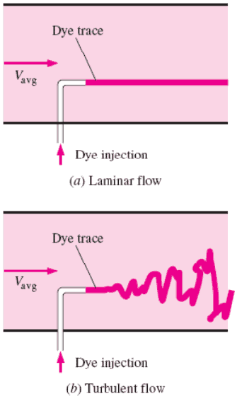
In fluid dynamics, laminar flow is characterized by smooth or in regular paths of particles of the fluid, in contrast to turbulent flow, that is characterized by the irregular movement of particles of the fluid. The fluid flows in parallel layers (with minimal lateral mixing), with no disruption between the layers. Therefore the laminar flow is also referred to as streamline or viscous flow.
The term streamline flow is descriptive of the flow because, in laminar flow, layers of water flowing over one another at different speeds with virtually no mixing between layers, fluid particles move in definite and observable paths or streamlines.
When a fluid is flowing through a closed channel such as a pipe or between two flat plates, either of two types of flow (laminar flow or turbulent flow) may occur depending on the velocity, viscosity of the fluid and the size of the pipe. Laminar flow tends to occur at lower velocities and high viscosity. On the other hand turbulent flow tends to occur at higher velocities and low viscosity.
Since laminar flow is common only in cases in which the flow channel is relatively small, the fluid is moving slowly, and its viscosity is relatively high, laminar flow is not common in industrial processes. Most industrial flows, especially those in nuclear engineering are turbulent. Nevertheless laminar flow occurs at any Reynolds number near solid boundaries in a thin layer just adjacent to the surface, this layer is usually referred to as the laminar sublayer and it is very important in heat transfer.
Despite the small thickness of the laminar sublayer (usually much less than 1 percent of the pipe diameter), since it strongly influences the flow in the rest of the pipe. Any irregularity or roughness on the surface disturbs this layer and significantly affects the flow. Therefore, unlike laminar flow, the friction factor in turbulent flow is a strong function of surface roughness.
Reynolds Number
The Reynolds number is the ratio of inertial forces to viscous forces and is a convenient parameter for predicting if a flow condition will be laminar or turbulent. It can be interpreted that when the viscous forces are dominant (slow flow, low Re) they are sufficient enough to keep all the fluid particles in line, then the flow is laminar. Even very low Re indicates viscous creeping motion, where inertia effects are negligible. When the inertial forces dominate over the viscous forces (when the fluid is flowing faster and Re is larger) then the flow is turbulent.
It is a dimensionless number comprised of the physical characteristics of the flow. An increasing Reynolds number indicates an increasing turbulence of flow.
It is defined as:
where:
V is the flow velocity,
D is a characteristic linear dimension, (travelled length of the fluid; hydraulic diameter etc.)
ρ fluid density (kg/m3),
μ dynamic viscosity (Pa.s),
ν kinematic viscosity (m2/s); ν = μ / ρ.
Charts: Viscosity and Density of Water (16MPa)
[/su_accordion]
Laminar vs. Turbulent Flow
Laminar Flow:
Re < 2000
‘low’ velocity
Fluid particles move in straight lines
Layers of water flow over one another at different speeds with virtually no mixing between layers.
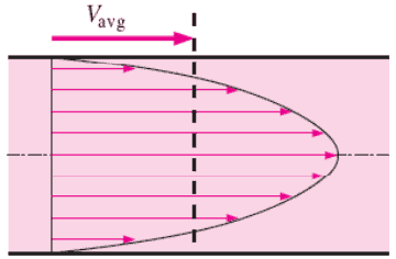
The flow velocity profile for laminar flow in circular pipes is parabolic in shape, with a maximum flow in the center of the pipe and a minimum flow at the pipe walls.
The average flow velocity is approximately one half of the maximum velocity.
Simple mathematical analysis is possible.
Rare in practice in water systems.
Turbulent Flow:
Re > 4000
‘high’ velocity
The flow is characterized by the irregular movement of particles of the fluid.
Average motion is in the direction of the flow
The flow velocity profile for turbulent flow is fairly flat across the center section of a pipe and drops rapidly extremely close to the walls.
The average flow velocity is approximately equal to the velocity at the center of the pipe.
Mathematical analysis is very difficult.
Most common type of flow.
Average velocity Vavg is defined as the average speed through a cross section. For fully developed laminar pipe flow, Vavg is half of the maximum velocity.
Classification of Flow Regimes
From a practical engineering point of view the flow regime can be categorized according to several criteria.
All fluid flow is classified into one of two broad categories or regimes. These two flow regimes are:
Single-phase Fluid Flow
Multi-phase Fluid Flow (or Two-phase Fluid Flow)
This is a basic classification. All of the fluid flow equations (e.g. Bernoulli’s Equation) and relationships that were discussed in this section (Fluid Dynamics) were derived for the flow of a single phase of fluid whether liquid or vapor. Solution of multi-phase fluid flow is very complex and difficult and therefore it is usually in advanced courses of fluid dynamics.
Another usually more common classification of flow regimes is according to the shape and type of streamlines. All fluid flow is classified into one of two broad categories. The fluid flow can be either laminar or turbulent and therefore these two categories are:
Laminar Flow
Turbulent Flow
Laminar flow is characterized by smooth or in regular paths of particles of the fluid. Therefore the laminar flow is also referred to as streamline or viscous flow. In contrast to laminar flow, turbulent flow is characterized by the irregular movement of particles of the fluid. The turbulent fluid does not flow in parallel layers, the lateral mixing is very high, and there is a disruption between the layers. Most industrial flows, especially those in nuclear engineering are turbulent.
The flow regime can be also classified according to the geometry of a conduit or flow area. From this point of view, we distinguish:
Internal Flow
External Flow
Internal flow is a flow for which the fluid is confined by a surface. Detailed knowledge of behaviour of internal flow regimes is of importance in engineering, because circular pipes can withstand high pressures and hence are used to convey liquids. On the other hand, external flow is such a flow in which boundary layers develop freely, without constraints imposed by adjacent surfaces. Detailed knowledge of behaviour of external flow regimes is of importance especially in aeronautics and aerodynamics.
Reynolds Number Regimes
Laminar flow. For practical purposes, if the Reynolds number is less than 2000, the flow is laminar. The accepted transition Reynolds number for flow in a circular pipe is Red,crit = 2300.
Transitional flow. At Reynolds numbers between about 2000 and 4000 the flow is unstable as a result of the onset of turbulence. These flows are sometimes referred to as transitional flows.
Turbulent flow. If the Reynolds number is greater than 3500, the flow is turbulent. Most fluid systems in nuclear facilities operate with turbulent flow.
Example: Reynolds number for a primary piping and a fuel bundle
It is an illustrative example, following data do not correspond to any reactor design.
Pressurized water reactors are cooled and moderated by high-pressure liquid water (e.g. 16MPa). At this pressure water boils at approximately 350°C (662°F). Inlet temperature of the water is about 290°C (⍴ ~ 720 kg/m3). The water (coolant) is heated in the reactor core to approximately 325°C (⍴ ~ 654 kg/m3) as the water flows through the core.
The hydraulic diameter of fuel rods bundle.
The primary circuit of typical PWRs is divided into 4 independent loops (piping diameter ~ 700mm), each loop comprises a steam generatorand one main coolant pump. Inside the reactor pressure vessel (RPV), the coolant first flows down outside the reactor core (through the downcomer). From the bottom of the pressure vessel, the flow is reversed up through the core, where the coolant temperature increases as it passes through the fuel rods and the assemblies formed by them.
Assume:
the primary piping flow velocity is constant and equal to 17 m/s,
the core flow velocity is constant and equal to 5 m/s,
the hydraulic diameter of the fuel channel, Dh, is equal to 2 cm
the kinematic viscosity of the water at 290°C is equal to 0.12 x 10⁻⁶ m2/s
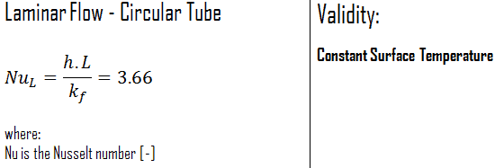
In laminar flow in a tube with constant surface temperature, both the friction factor and the heat transfer coefficient remain constant in the fully developed region.
Constant Surface Heat Flux
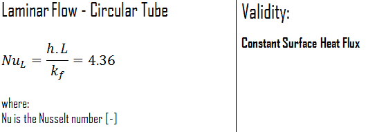
Therefore, for fully developed laminar flow in a circular tube subjected to constant surface heat flux, the Nusselt number is a constant. There is no dependence on the Reynolds or the Prandtl numbers.
References:
Reactor Physics and Thermal Hydraulics:
J. R. Lamarsh, Introduction to Nuclear Reactor Theory, 2nd ed., Addison-Wesley, Reading, MA (1983).
J. R. Lamarsh, A. J. Baratta, Introduction to Nuclear Engineering, 3d ed., Prentice-Hall, 2001, ISBN: 0-201-82498-1.
W. M. Stacey, Nuclear Reactor Physics, John Wiley & Sons, 2001, ISBN: 0- 471-39127-1.
Todreas Neil E., Kazimi Mujid S. Nuclear Systems Volume I: Thermal Hydraulic Fundamentals, Second Edition. CRC Press; 2 edition, 2012, ISBN: 978-0415802871
Zohuri B., McDaniel P. Thermodynamics in Nuclear Power Plant Systems. Springer; 2015, ISBN: 978-3-319-13419-2
Moran Michal J., Shapiro Howard N. Fundamentals of Engineering Thermodynamics, Fifth Edition, John Wiley & Sons, 2006, ISBN: 978-0-470-03037-0
Kleinstreuer C. Modern Fluid Dynamics. Springer, 2010, ISBN 978-1-4020-8670-0.
U.S. Department of Energy, THERMODYNAMICS, HEAT TRANSFER, AND FLUID FLOW. DOE Fundamentals Handbook, Volume 1, 2 and 3. June 1992.
White Frank M., Fluid Mechanics, McGraw-Hill Education, 7th edition, February, 2010, ISBN: 978-0077422417
See also:
Fluid Dynamics
We hope, this article, Laminar Flow – Viscous Flow, helps you. If so, give us a like in the sidebar. Main purpose of this website is to help the public to learn some interesting and important information about thermal engineering.