Diesel Cycle – Diesel Engine
Dual cycle, or limited pressure cycle, is a thermodynamic cycle that combines the Otto cycle and the Diesel cycle. In the dual cycle, combustion occurs partly at constant volume and partly at constant pressure. It can be used to describe internal combustion engines. The pressure–volume diagrams of actual internal combustion engines are not described well by the Otto and Diesel cycles. An air standard cycle that can be made to approximate the pressure variations more closely is the air-standard dual cycle. A more capable approach would be to model the combustion process in both Otto and Diesel engines as a combination of two heat-transfer processes, one isochoric process and one isobaric process.
In comparison to an Otto cycle, which assumes an instantaneous heat addition (isochoric heat addition), in a dual cycle heat is added partly at constant volume and partly at constant pressure. Therefore the advantage is that more time is available for the fuel to completely combust. On the other hand the use of a dual cycle is slightly more complex. The thermal efficiency lies between Otto and Diesel cycle.
Source: wikipedia.org, Own work of Zephyris, CC BY-SA 3.0
Dual Cycle – Processes
In a dual cycle, the system executing the cycle undergoes a series of five processes: two isentropic (reversible adiabatic) processes alternated with two isochoric process and one isobaric process:
-
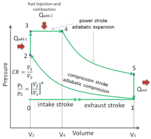
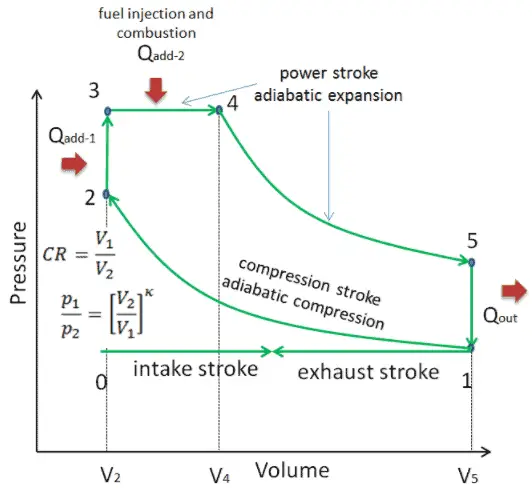
Dual cycle – pV Diagram Isentropic compression (compression stroke) – The gas is compressed adiabatically from state 1 to state 2, as the piston moves from intake valve closing point (1) to top dead center. The surroundings do work on the gas, increasing its internal energy (temperature) and compressing it. On the other hand the entropy remains unchanged. The changes in volumes and its ratio (V1 / V2) is known as the compression ratio. The compression ratio is smaller than the expansion ratio.
- Isochoric compression (ignition phase) – In this phase (between state 2 and state 3) there is a constant-volume (the piston is at rest ) heat transfer to the air from an external source while the piston is at rest at top dead center. This process is similar to the isochoric process in the Otto cycle. It is intended to represent the ignition of the fuel–air mixture injected into the chamber and the subsequent rapid burning. The pressure rises and the ratio (P3 / P2) is known as the “explosion ratio”.
- Isobaric expansion (power stroke) – In this phase (between state 3 and state 4) there is a constant-pressure (idealized model) heat transfer to the air from an external source (combustion of the fuel) while the piston is moving toward the V4. During the constant pressure process, energy enters the system as heat Qadd, and a part of work is done by moving piston.
- Isentropic expansion (power stroke) – The gas expands adiabatically from state 4 to state 5, as the piston moves from V3 to bottom dead center. The gas does work on the surroundings (piston) and loses an amount of internal energy equal to the work that leaves the system. Again the entropy remains unchanged.
- Isochoric decompression (exhaust stroke) – In this phase the cycle completes by a constant-volume process in which heat is rejected from the air while the piston is at bottom dead center. The working gas pressure drops instantaneously from point 5 to point 1. The exhaust valve opens at point 5. The exhaust stroke is directly after this decompression. As the piston moves from bottom dead center (point 1) to top dead center (point 0) with the exhaust valve opened, the gaseous mixture is vented to the atmosphere and the process starts anew.
During the Dual cycle, work is done on the gas by the piston between states 1 and 2 (isentropic compression). Work is done by the gas on the piston between stages 2 and 3 (isobaric heat addition) and between stages 2 and 3 (isentropic expansion). The difference between the work done by the gas and the work done on the gas is the net work produced by the cycle and it corresponds to the area enclosed by the cycle curve. The work produced by the cycle times the rate of the cycle (cycles per second) is equal to the power produced by the Diesel engine.
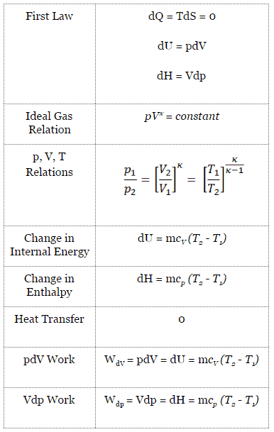
Isentropic Process
An isentropic process is a thermodynamic process, in which the entropy of the fluid or gas remains constant. It means the isentropic process is a special case of an adiabatic process in which there is no transfer of heat or matter. It is a reversible adiabatic process. The assumption of no heat transfer is very important, since we can use the adiabatic approximation only in very rapid processes.
Isentropic Process and the First Law
For a closed system, we can write the first law of thermodynamics in terms of enthalpy:
dH = dQ + Vdp
or
dH = TdS + Vdp
Isentropic process (dQ = 0):
dH = Vdp → W = H2 – H1 → H2 – H1 = Cp (T2 – T1) (for ideal gas)
Isentropic Process of the Ideal Gas
The isentropic process (a special case of adiabatic process) can be expressed with the ideal gas law as:
pVκ = constant
or
p1V1κ = p2V2κ
in which κ = cp/cv is the ratio of the specific heats (or heat capacities) for the gas. One for constant pressure (cp) and one for constant volume (cv). Note that, this ratio κ = cp/cv is a factor in determining the speed of sound in a gas and other adiabatic processes.
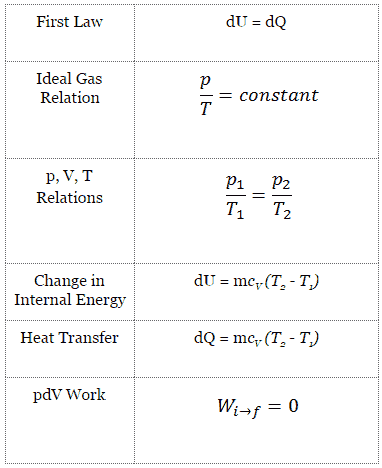
Isochoric Process
An isochoric process is a thermodynamic process, in which the volume of the closed system remains constant (V = const). It describes the behavior of gas inside the container, that cannot be deformed. Since the volume remains constant, the heat transfer into or out of the system does not the p∆V work, but only changes the internal energy (the temperature) of the system.
Isochoric Process and the First Law
The classical form of the first law of thermodynamics is the following equation:
dU = dQ – dW
In this equation dW is equal to dW = pdV and is known as the boundary work. Then:
dU = dQ – pdV
In isochoric process and the ideal gas, all of heat added to the system will be used to increase the internal energy.
Isochoric process (pdV = 0):
dU = dQ (for ideal gas)
dU = 0 = Q – W → W = Q (for ideal gas)
Isochoric Process of the Ideal Gas
The isochoric process can be expressed with the ideal gas law as:
or

On a p-V diagram, the process occurs along a horizontal line that has the equation V = constant.
See also: Guy-Lussac’s Law
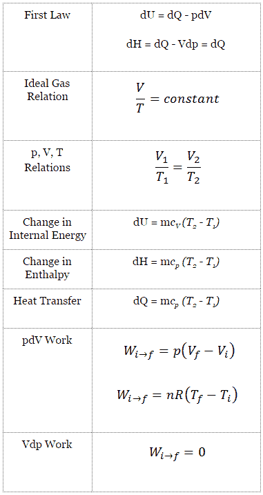
Isobaric Process
An isobaric process is a thermodynamic process, in which the pressure of the system remains constant (p = const). The heat transfer into or out of the system does work, but also changes the internal energy of the system.
Since there are changes in internal energy (dU) and changes in system volume (∆V), engineers often use the enthalpy of the system, which is defined as:
H = U + pV
Isobaric Process and the First Law
The classical form of the first law of thermodynamics is the following equation:
dU = dQ – dW
In this equation dW is equal to dW = pdV and is known as the boundary work. In an isobaric process and the ideal gas, part of heat added to the system will be used to do work and part of heat added will increase the internal energy (increase the temperature). Therefore it is convenient to use the enthalpy instead of the internal energy.
Isobaric process (Vdp = 0):
dH = dQ → Q = H2– H1
At constant entropy, i.e. in isentropic process, the enthalpy change equals the flow process work done on or by the system.
Isobaric Process of the Ideal Gas
The isobaric process can be expressed with the ideal gas law as:
or

On a p-V diagram, the process occurs along a horizontal line (called an isobar) that has the equation p = constant.
See also: Charles’s Law
Thermal Efficiency for Dual Cycle
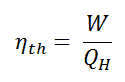
In general the thermal efficiency, ηth, of any heat engine is defined as the ratio of the work it does, W, to the heat input at the high temperature, QH.
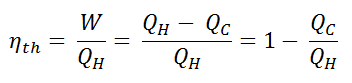
The thermal efficiency, ηth, represents the fraction of heat, QH, that is converted to work. Since energy is conserved according to the first law of thermodynamics and energy cannot be be converted to work completely, the heat input, QH, must equal the work done, W, plus the heat that must be dissipated as waste heat QC into the environment. Therefore we can rewrite the formula for thermal efficiency as:
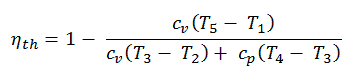
Therefore the heat added and rejected are given by:
Qadd-1 = mcv (T3 – T2)
Qadd-2 = mcp (T4 – T3)
Qout = mcv (T5 – T1)
Therefore the thermal efficiency for a dual cycle is:
We hope, this article, Dual Cycle – Limited Pressure Cycle, helps you. If so, give us a like in the sidebar. Main purpose of this website is to help the public to learn some interesting and important information about thermal engineering.