Turbine Generator – Power Conversion System
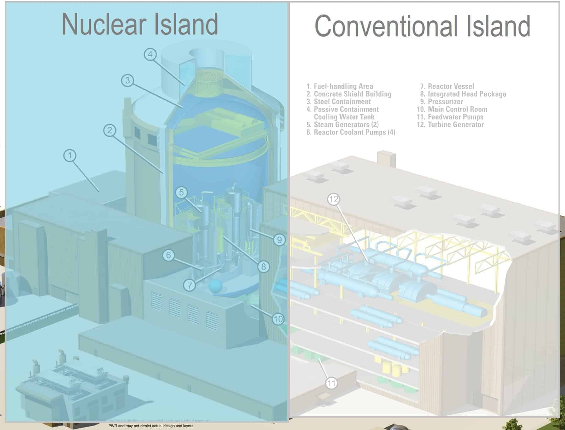
The layout of nuclear power plants comprises two major parts: The nuclear island and the conventional (turbine) island. The nuclear island is the heart of the nuclear power plant. On the other hand the conventional (turbine) island houses the key component which extracts thermal energy from pressurized steam and converts it into electrical energy, the turbine generator. Therefore it is also known as the power conversion system. The key device of power conversion system is the turbine generator. The turbine generator is in the turbine building and contains most of the main components of the thermodynamic cycle. Only the steam generators are situated in the reactor building (the nuclear island).
Note that, we are describing the power conversion system of a pressurized water reactor (PWR). A boiling water reactor (BWR) is like a pressurized water reactor but with many differences. The BWRs don’t have any steam generator. Unlike a PWR, there is no primary and secondary loop. Basically, the turbine island of BWRs is very similar to PWRs.
Since the conventional power plants (e.g. fossil-fuel power plants) use very similar technology to convert thermal energy into electrical energy, this part of nuclear power plant is called “conventional island”. In comparison to conventional power plants the conventional island at nuclear power plants must fulfill the significantly stricter specification on quality assurance and control that applies to even conventional parts of the nuclear power plant due to the impact they may have on the nuclear systems.
The key components of power conversion system:
- Steam Turbine. A steam turbine is a device that extracts thermal energy from pressurized steam and uses it to do mechanical work on a rotating output shaft.
- Generator. A generator is a device that converts mechanical energy of the steam turbine to electrical energy.
- Steam Generator. Steam generators are heat exchangers used to convert feedwater into steam from heat produced in a nuclear reactor core.
- Condenser. A condenser is a heat exchanger used to condense steam from last stage of turbine.
- Condensate-Feedwater System. Condensate-Feedwater Systems have two major functions. To supply adequate high quality water (condensate) to the steam generator and to heat the water (condensate) to a temperature close to saturation.
- Moisture Separator Reheater (MSR). The moisture separator reheaters are usually installed between the high pressure turbine outlet and the low pressure turbine inlets to remove the moisture from the high pressure turbine exhaust steam and to reheat this steam before admitted to the LP turbines.
- Cooling System. The primary function for cooling system in power plants is to cool the steam circuit so as to condense the low-pressure steam and recycle it. As the steam in the internal circuit condenses back to water, the surplus (waste) heat which is removed from it needs to be discharged by transfer to the air or to a body of water.
- Instrumentation and Control System (I&C). The instrumentation and control system serves as the central nervous system of a nuclear power plant.
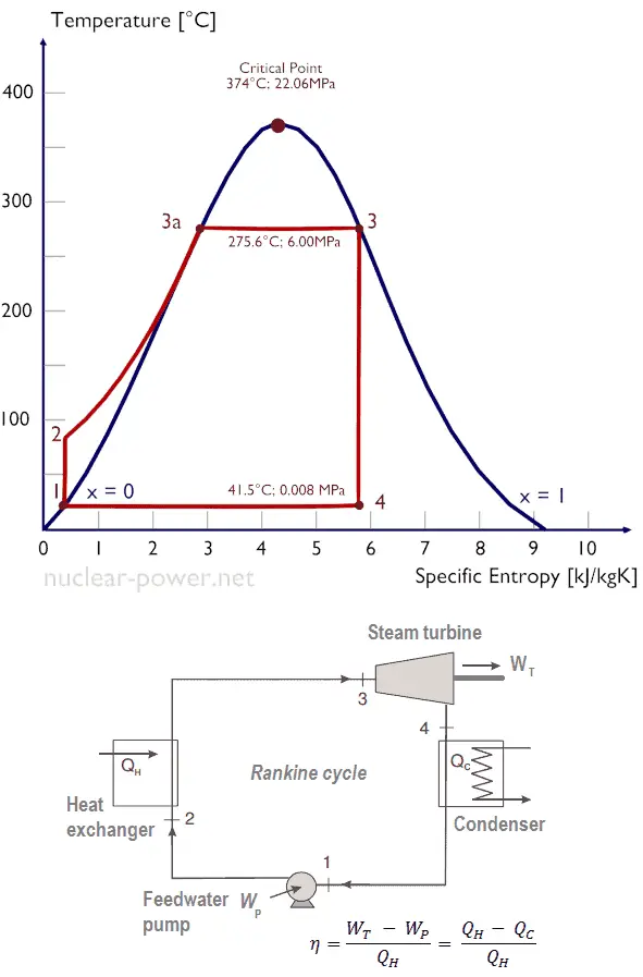
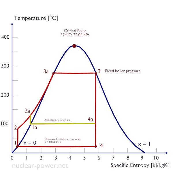
Ts diagram of the Rankine cycle. The Rankine cycle was named after a Scottish engineer, William John Macquorn Rankine and describes the performance of steam turbine systems.
Principle of Operation of Turbine Generator – Electricity Generation
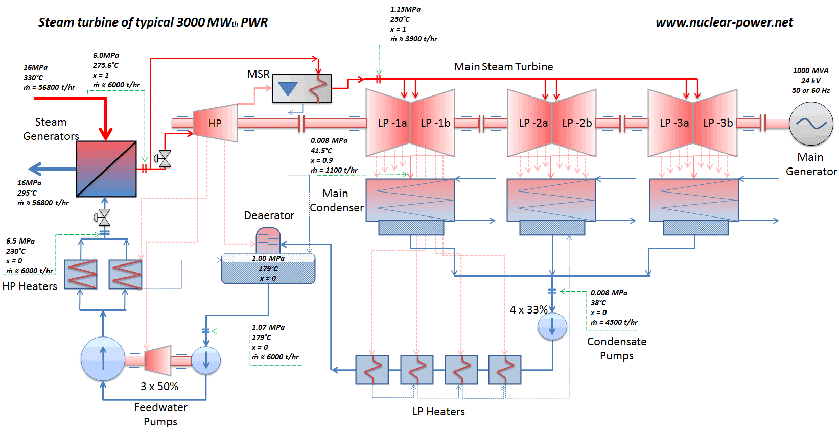
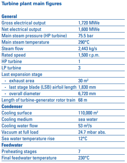
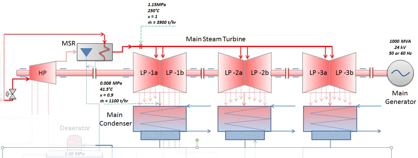
Most of nuclear power plants operates a single-shaft turbine-generator that consists of one multi-stage HP turbine and three parallel multi-stage LP turbines, a main generator and an exciter. HP Turbine is usually double-flow impulse turbine (or reaction type) with about 10 stages with shrouded blades and produces about 30-40% of the gross power output of the power plant unit. LP turbines are usually double-flow reaction turbines with about 5-8 stages (with shrouded blades and with free-standing blades of last 3 stages). LP turbines produce approximately 60-70% of the gross power output of the power plant unit. Each turbine rotor is mounted on two bearings, i.e. there are double bearings between each turbine module.
From Steam Generator to Main Steam Lines – Evaporation
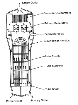
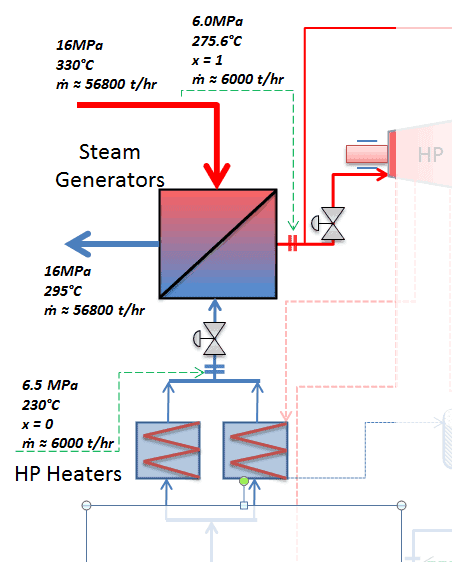
The power conversion system of typical PWR begins in the steam generators in their shell sides. Steam generators are heat exchangers used to convert feedwater into steam from heat produced in a nuclear reactor core. The feedwater (secondary circuit) is heated from ~230°C 500°F (preheated fluid by regenerators) to the boiling point of that fluid (280°C; 536°F; 6,5MPa). Heat is transferred through the walls of these tubes to the lower pressure secondary coolant located on the secondary side of the exchanger where the coolant evaporates to pressurized steam (saturated steam 280°C; 536°F; 6,5 MPa). The saturated steam leaves the steam generator through a steam outlet and continues to the main steam lines and further to the steam turbine.
 These main steam lines are cross-tied (e.g. via steam collector pipe) near the turbine to ensure that the pressure difference between any of the steam generators does not exceed specific value thus maintaining system balance and ensuring uniform heat removal from the Reactor Coolant System (RCS). The steam flows through the main steam line isolation valves (MSIVs), which are very important from safety point of view, to the high pressure turbine. Directly at the inlet of the steam turbine, there are throttle-stop valves and control valves. Turbine control is achieved by varying these turbine valves openings. In the event of a turbine trip, the steam supply must be isolated very quickly, usually in the fraction of a second, so the stop valves must operate quickly and reliably.
Calculate the amount of primary coolant, which is required to evaporate 1 kg of feedwater in a typical steam generator. Assume that there are no energy losses, this is only idealized example.
Balance of the primary circuit
The hot primary coolant (water 330°C; 626°F; 16MPa) is pumped into the steam generator through primary inlet. The primary coolant leaves (water 295°C; 563°F; 16MPa) the steam generator through primary outlet.
hI, inlet = 1516 kJ/kg
=> ΔhI = -206 kJ/kg
hI, outlet = 1310 kJ/kg
Balance of the feedwater

The feedwater (water 230°C; 446°F; 6,5MPa) is pumped into the steam generator through the feedwater inlet. The feedwater (secondary circuit) is heated from ~230°C 446°F to the boiling point of that fluid (280°C; 536°F; 6,5MPa). Feedwater is then evaporated and the pressurized steam (saturated steam 280°C; 536°F; 6,5 MPa) leaves the steam generator through steam outlet and continues to the steam turbine.
hII, inlet = 991 kJ/kg
=> ΔhII = 1789 kJ/kg
hII, outlet = 2780 kJ/kg
Balance of the steam generator
Since the difference in specific enthalpies is less for primary coolant than for feedwater, it is obvious that the amount of primary coolant will be higher than 1kg. To produce of 1 kg of saturated steam from feedwater, about 1789/206 x 1 kg = 8.68 kg of primary coolant is required.
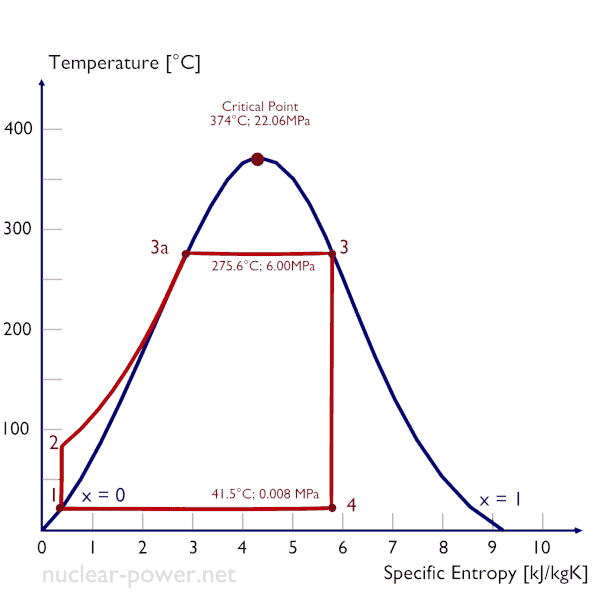
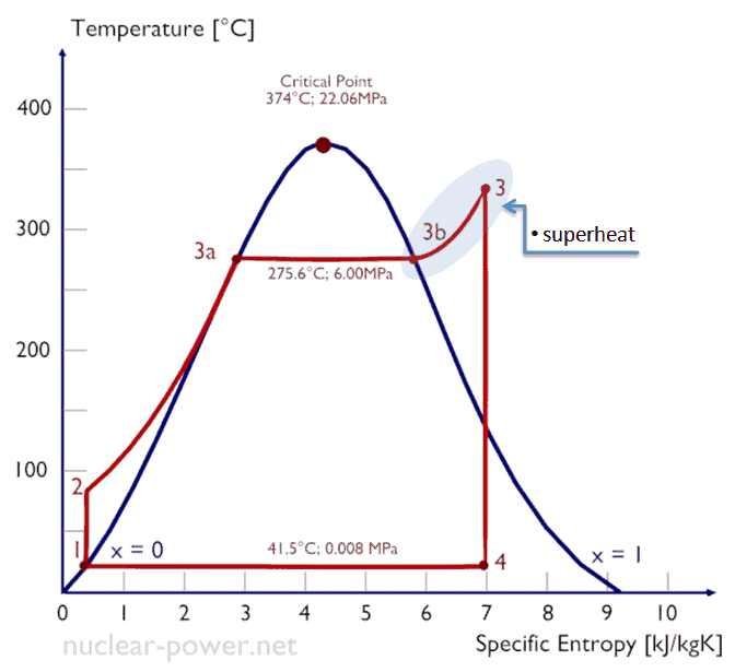
Isobaric heat addition (in a heat exchanger – boiler) – In this phase (between state 2 and state 3) there is a constant-pressure heat transfer to the liquid condensate from an external source, since the chamber is open to flow in and out. The feedwater (secondary circuit) is heated from to the boiling point (2 → 3a) of that fluid and then evaporated in the boiler (3a → 3). The net heat added is given by Qadd = H3 – H2
From Turbine Valves to Condenser – Expansion
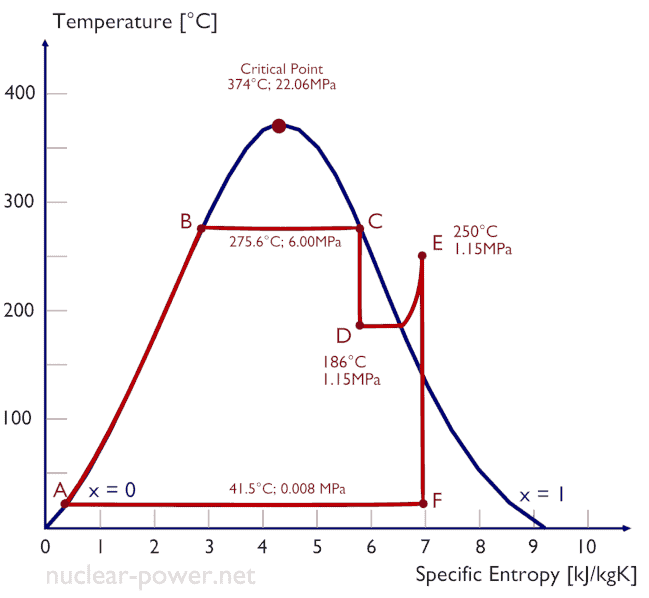
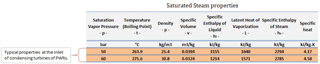
Typically most of nuclear power plants operates multi-stage condensing steam turbines. In these turbines the high-pressure stage receives steam (this steam is nearly saturated steam – x = 0.995 – point C at the figure; 6 MPa; 275.6°C) from a steam generator and exhaust it to moisture separator-reheater (MSR – point D). The steam must be reheated in order to avoid damages that could be caused to blades of steam turbine by low quality steam. High content of water droplets can cause the rapid impingement and erosion of the blades which occurs when condensed water is blasted onto the blades. To prevent this, condensate drains are installed in the steam piping leading to the turbine. The moisture-free steam is superheated by extraction steam from the high-pressure stage of turbine and by steam directly from the main steam lines.
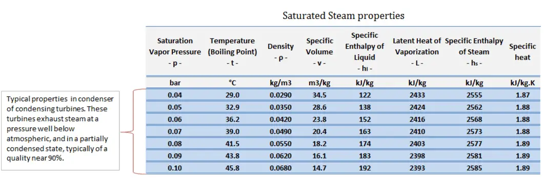
The heating steam is condensed in the tubes and is drained to the feedwater system. The reheater heats the steam (point D) and then the steam is directed to the low-pressure stage of steam turbine, where expands (point E to F). The exhausted steam then condenses in the condenser and it is at a pressure well below atmospheric (absolute pressure of 0.008 MPa), and is in a partially condensed state (point F), typically of a quality near 90%. High pressure and low pressure stages of the turbine are usually on the same shaft to drive a common generator, but they have separate cases. The main generator produces electrical power, which is supplied to the electrical grid.
Isentropic expansion (expansion in a steam turbine) – Steam from the boiler expands adiabatically from state 3 to state 4 in a steam turbine to produce work and then is discharged to the condenser (partially condensed). The steam does work on the surroundings (blades of the turbine) and loses an amount of enthalpy equal to the work that leaves the system. The work done by turbine is given by WT = H4 – H3. Again the entropy remains unchanged.
From Condenser to Condensate Pumps – Condensation
 The main condenser condenses the exhaust steam from the low-pressure stages of the main turbine and also from the steam dump system. The exhausted steam is condensed by passing over tubes containing water from the cooling system.
The pressure inside condenser is given by the ambient air temperature (i.e. temperature of water in the cooling system) and by steam ejectors or vacuum pumps, which pull the gases (non-condensibles) from the surface condenser and eject them to the atmosphere.
The lowest feasible condenser pressure is the saturation pressure corresponding to the ambient temperature (e.g. absolute pressure of 0.008 MPa, which corresponds to 41.5°C). Note that, there is always a temperature difference between (around ΔT = 14°C) the condenser temperature and the ambient temperature, which originates from finite size and efficiency of condensers. Since neither the condenser is 100% efficient heat exchanger, there is always a temperature difference between the saturation temperature (secondary side) and the temperature of the coolant in the cooling system. Moreover, there is a design inefficiciency, which decreases the overall efficiency of the turbine. Ideally the steam exhausted into the condenser would have no subcooling. But real condensers are designed to subcool the liquid by a few degrees of Celsius in order to avoid the suction cavitation in the condensate pumps. But, this subcooling increases the inefficiency of the cycle, because more energy is needed to reheat the water.
The goal of maintaining the lowest practical turbine exhaust pressure is a primary reason for including the condenser in a thermal power plant. The condenser provides a vacuum that maximizes the energy extracted from the steam, resulting in a significant increase in net work and thermal efficiency. But also this parameter (condenser pressure) has its engineering limits:
- Decreasing the turbine exhaust pressure decreases the vapor quality (or dryness fraction). At some point the expansion must be ended to avoid damages that could be caused to blades of steam turbine by low quality steam.
- Decreasing the turbine exhaust pressure significantly increases the specific volume of exhausted steam, which requires huge blades in last rows of low-pressure stage of the steam turbine.
In a typical wet steam turbine, the exhausted steam condenses in the condenser and it is at a pressure well below atmospheric (absolute pressure of 0.008 MPa, which corresponds to 41.5°C). This steam is in a partially condensed state (point F), typically of a quality near 90%. Note that, the pressure inside the condenser is also dependent on the ambient atmospheric conditions:
- air temperature, pressure and humidity in case of cooling into the atmosphere
- water temperature and the flow rate in case of cooling into a river or sea
An increase in the ambient temperature causes a proportional increase in pressure of exhausted steam (ΔT = 14°C is usually a constant) hence the thermal efficiency of the power conversion system decreases. In other words, the electrical output of a power plant may vary with ambient conditions, while the thermal power remains constant.
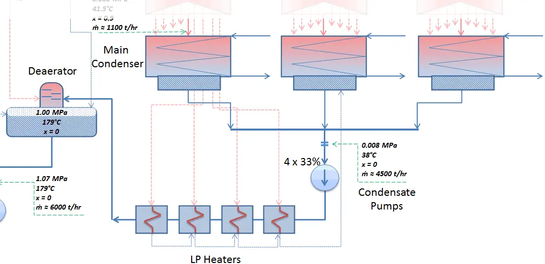
The condensed steam (now called condensate) is collected in the condenser’s hotwell. Condenser’s hotwell provides also a water storage capacity, which is required for operational purposes such as feedwater makeup. The condensate (saturated or slightly subcooled liquid) is delivered to the condensate pump and then pumped by condensate pumps to the deaerator through feedwater heating system. The condensate pumps increase the pressure usually to about p = 1-2 MPa. There are usually four one-third-capacity centrifugal condensate pumps with common suction and discharge headers. Three pumps are normally in operation with one in the backup.
From Condensate Pumps to Feedwater Pumps – Heat Regeneration
The condensate from condensate pumps then passes through several stages of low pressure feedwater heaters, in which the temperature of the condensate is increased by heat transfer from steam extracted from the low pressure turbines. There are usually three or four stages of low pressure feedwater heaters connected in the cascade. The condensate exits the low pressure feedwater heaters at approximately p = 1 MPa, t = 150°C and enters the deaerator. The main condensate system also contains a mechanical condensate purification system for removing impurities. The feedwater heaters are self-regulating. It means that the greater the flow of feedwater the greater the rate of heat absorption from the steam and the greater the flow of extraction steam.
There are non-return valves in the extraction steam lines between the feedwater heaters and turbine. These non-return valves prevent the reverse steam or water flow in case of turbine trip, which causes rapid decrease in the pressure inside the turbine. Any water entering the turbine in this way could cause severe damage to the turbine blading.
Deaerator
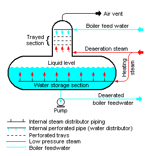
In general, a deaerator is a device that is used for the removal of oxygen and other dissolved gases from the feedwater to steam generators. The deaerator is part of the feedwater heating system. It is usually situated between the last low pressure heater and feedwater booster pumps. In particular, dissolved oxygen in the steam generator can cause serious corrosion damage by attaching to the walls of metal piping and other metallic equipment and forming oxides (rust). Furthermore, dissolved carbon dioxide combines with water to form carbonic acid that causes further corrosion.
In the deaerator, the condensate is heated to saturated conditions usually by the steam extracted from the steam turbine. The extraction steam are mixed in the deaerator by a system of spray nozzles and cascading trays between which the steam percolates. Any dissolved gases in the condensate are released in this process and removed from the deaerator by venting to the atmosphere or to the main condenser. Directly below the deaerator is the feedwater storage tank, in which a large quantity of feedwater is stored at near saturation conditions. In the turbine trip event, this feedwater can be supplied to steam generators to maintain the required water inventory during transient. The deaerator and the storage tank is usually located at a high elevation in the turbine hall to ensure an adequate net positive suction head (NPSH) at the inlet to the feedwater pumps. NPSH is used to measure how close a fluid is to saturated conditions. Lowering the pressure at the suction side can induce cavitation. This arrangement minimizes the risk of cavitation in the pump.
From Feedwater Pumps to Steam Generator
 The system of feedwater pumps usually contains of three parallel lines (3×50%) of feedwater pumps with common suction and discharge headers. Each feedwater pump consist of the booster and the main feedwater pump. The feedwater pumps (usually driven by steam turbines) increase the pressure of the condensate (~1MPa) to the pressure in the steam generator (~6.5MPa).
The booster pumps provide the required main feedwater pump suction pressure. These pumps (both feedwater pumps) are normally high pressure pumps (usually of the centrifugal pump type) that take suction from the deaerator water storage tank, which is mounted directly below the deaerator, and supply the main feedwater pumps. The water discharge from the feedwater pumps flows through the high pressure feedwater heaters, enters the containment and then flows into the steam generators.
Feedwater flow to each steam generator is controlled by feedwater regulating valves (FRVs) in each feedwater line. The regulator is controlled automatically by steam generator level, steam flow and feedwater flow.
The high pressure feedwater heaters are heated by extraction steam from the high pressure turbine, HP Turbine. Drains from the high-pressure feedwater heaters are usually routed to the deaerator.
The feedwater (water 230°C; 446°F; 6,5MPa) is pumped into the steam generator through the feedwater inlet. In the steam generator is the feedwater (secondary circuit) heated from ~230°C 446°F to the boiling point of that fluid (280°C; 536°F; 6,5MPa). Feedwater is then evaporated and the pressurized steam (saturated steam 280°C; 536°F; 6,5 MPa) leaves the steam generator through steam outlet and continues to the steam turbine, thereby completing the cycle.
Thermal Efficiency of Steam Turbines
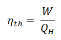
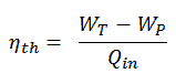
In general the thermal efficiency, ηth, of any heat engine is defined as the ratio of the work it does, W, to the heat input at the high temperature, QH.
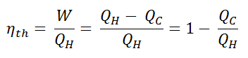
The thermal efficiency, ηth, represents the fraction of heat, QH, that is converted to work. Since energy is conserved according to the first law of thermodynamics and energy cannot be be converted to work completely, the heat input, QH, must equal the work done, W, plus the heat that must be dissipated as waste heat QC into the environment. Therefore we can rewrite the formula for thermal efficiency as:
This is very useful formula, but here we express the thermal efficiency using the first law in terms of enthalpy.
Typically most of nuclear power plants operates multi-stage condensing steam turbines. In these turbines the high-pressure stage receives steam (this steam is nearly saturated steam – x = 0.995 – point C at the figure; 6 MPa; 275.6°C) from a steam generator and exhaust it to moisture separator-reheater (point D). The steam must be reheated in order to avoid damages that could be caused to blades of steam turbine by low quality steam. The reheater heats the steam (point D) and then the steam is directed to the low-pressure stage of steam turbine, where expands (point E to F). The exhausted steam then condenses in the condenser and it is at a pressure well below atmospheric (absolute pressure of 0.008 MPa), and is in a partially condensed state (point F), typically of a quality near 90%.
In this case, steam generators, steam turbine, condensers and feedwater pumps constitute a heat engine, that is subject to the efficiency limitations imposed by the second law of thermodynamics. In ideal case (no friction, reversible processes, perfect design), this heat engine would have a Carnot efficiency of
= 1 – Tcold/Thot = 1 – 315/549 = 42.6%
where the temperature of the hot reservoir is 275.6°C (548.7K), the temperature of the cold reservoir is 41.5°C (314.7K). But the nuclear power plant is the real heat engine, in which thermodynamic processes are somehow irreversible. They are not done infinitely slowly. In real devices (such as turbines, pumps, and compressors) a mechanical friction and heat losses cause further efficiency losses.
To calculate the thermal efficiency of the simplest Rankine cycle (without reheating) engineers use the first law of thermodynamics in terms of enthalpy rather than in terms of internal energy.
The first law in terms of enthalpy is:
dH = dQ + Vdp
In this equation the term Vdp is a flow process work. This work, Vdp, is used for open flow systems like a turbine or a pump in which there is a “dp”, i.e. change in pressure. There are no changes in control volume. As can be seen, this form of the law simplifies the description of energy transfer. At constant pressure, the enthalpy change equals the energy transferred from the environment through heating:
Isobaric process (Vdp = 0):
dH = dQ → Q = H2 – H1
At constant entropy, i.e. in isentropic process, the enthalpy change equals the flow process work done on or by the system:
Isentropic process (dQ = 0):
dH = Vdp → W = H2 – H1
It is obvious, it will be very useful in analysis of both thermodynamic cycles used in power engineering, i.e. in Brayton cycle and Rankine cycle.
The enthalpy can be made into an intensive, or specific, variable by dividing by the mass. Engineers use the specific enthalpy in thermodynamic analysis more than the enthalpy itself. It is tabulated in the steam tables along with specific volume and specific internal energy. The thermal efficiency of such simple Rankine cycle and in terms of specific enthalpies would be:
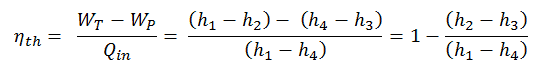
It is very simple equation and for determination of the thermal efficiency you can use data from steam tables.
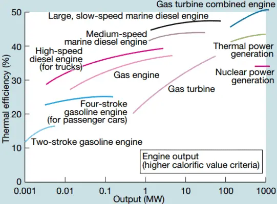
In modern nuclear power plants the overall thermal efficiency is about one-third (33%), so 3000 MWth of thermal power from the fission reaction is needed to generate 1000 MWe of electrical power. The reason lies in relatively low steam temperature (6 MPa; 275.6°C). Higher efficiencies can be attained by increasing the temperature of the steam. But this requires an increase in pressures inside boilers or steam generators. However, metallurgical considerations place an upper limits on such pressures. In comparison to other energy sources the thermal efficiency of 33% is not much. But it must be noted that nuclear power plants are much more complex than fossil fuel power plants and it is much easier to burn fossil fuel ,than to generate energy from nuclear fuel. Sub-critical fossil fuel power plants, that are operated under critical pressure (i.e. lower than 22.1 MPa), can achieve 36–40% efficiency.
Causes of Inefficiency
As was discussed, an efficiency can range between 0 and 1. Each heat engine is somehow inefficient. This inefficiency can be attributed to three causes.
- Irreversibility of Processes. There is an overall theoretical upper limit to the efficiency of conversion of heat to work in any heat engine. This upper limit is called the Carnot efficiency. According to the Carnot principle, no engine can be more efficient than a reversible engine (a Carnot heat engine) operating between the same high temperature and low temperature reservoirs. For example, when the hot reservoir have Thot of 400°C (673K) and Tcold of about 20°C (293K), the maximum (ideal) efficiency will be: = 1 – Tcold/Thot = 1 – 293/673 = 56%. But all real thermodynamic processes are somehow irreversible. They are not done infinitely slowly. Therefore, heat engines must have lower efficiencies than limits on their efficiency due to the inherent irreversibility of the heat engine cycle they use.
- Presence of Friction and Heat Losses. In real thermodynamic systems or in real heat engines, a part of the overall cycle inefficiency is due to the losses by the individual components. In real devices (such as turbines, pumps, and compressors) a mechanical friction, heat losses and losses in the combustion process cause further efficiency losses.
- Design Inefficiency. Finally, last and also important source of inefficiencies is from the compromises made by engineers when designing a heat engine (e.g. power plant). They must consider cost and other factors in the design and operation of the cycle. As an example consider a design of the condenser in the thermal power plants. Ideally the steam exhausted into the condenser would have no subcooling. But real condensers are designed to subcool the liquid by a few degrees of Celsius in order to avoid the suction cavitation in the condensate pumps. But, this subcooling increases the inefficiency of the cycle, because more energy is needed to reheat the water.
Thermal Efficiency Improvement – Rankine Cycle
There are several methods, how can be the thermal efficiency of the Rankine cycle improved. Assuming that the maximum temperature is limited by the pressure inside the reactor pressure vessel, these methods are:
Condenser Pressure
The case of the decrease in the average temperature at which energy is rejected, requires a decrease in the pressure inside condenser (i.e. the decrease in the saturation temperature). The lowest feasible condenser pressure is the saturation pressure corresponding to the ambient temperature (i.e. absolute pressure of 0.008 MPa, which corresponds to 41.5°C). The goal of maintaining the lowest practical turbine exhaust pressure is a primary reason for including the condenser in a thermal power plant. The condenser provides a vacuum that maximizes the energy extracted from the steam, resulting in a significant increase in net work and thermal efficiency. But also this parameter (condenser pressure) has its engineering limits:
- Decreasing the turbine exhaust pressure decreases the vapor quality (or dryness fraction). At some point the expansion must be ended to avoid damages that could be caused to blades of steam turbine by low quality steam.
- Decreasing the turbine exhaust pressure significantly increases the specific volume of exhausted steam, which requires huge blades in last rows of low-pressure stage of the steam turbine.
In a typical wet steam turbines, the exhausted steam condenses in the condenser and it is at a pressure well below atmospheric (absolute pressure of 0.008 MPa, which corresponds to 41.5°C). This steam is in a partially condensed state (point F), typically of a quality near 90%. Note that, there is always a temperature difference between (around ΔT = 14°C) the condenser temperature and the ambient temperature, which originates from finite size and efficiency of condensers.
Boiler Pressure
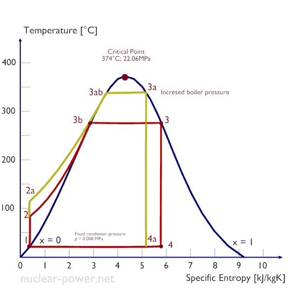
The case of the increase in the average temperature at which energy is added by heat transfer, requires either a superheating of steam produced or an increase in the pressure in the boiler (steam generator). Superheating is not typical for nuclear power plants.
Typically most of nuclear power plants operates multi-stage condensing steam turbines. In these turbines the high-pressure stage receives steam (this steam is nearly saturated steam – x = 0.995 – point C at the figure; 6 MPa; 275.6°C). Since neither the steam generator is 100% efficient, there is always a temperature difference between the saturation temperature (secondary side) and the temperature of the primary coolant.
In a typical pressurized water reactor, the hot primary coolant (water 330°C; 626°F) is pumped into the steam generator through primary inlet. This requires maintaining of very high pressures to keep the water in the liquid state. In order to prevent boiling of the primary coolant and to provide a subcooling margin (the difference between the pressurizer temperature and the highest temperature in the reactor core), pressures around 16 MPa are typical for PWRs. The reactor pressure vessel is the key component, which limits the thermal efficiency of each nuclear power plant, since the reactor vessel must withstand high pressures.
 As for the Carnot cycle, the thermal efficiency tends to increase as the average temperature at which energy is added by heat transfer increases. This is the common feature of all thermodynamic cycles.
One of possible ways is to superheat or reheat the working steam. Both processes are very similar in its manner:
- Superheater – increases the steam temperature above the saturation temperature
- Reheater – removes the moisture and increases steam temperature after a partial expansion.
The process of superheating is the only way to increase the peak temperature of the Rankine cycle (and to increase efficiency) without increasing the boiler pressure. This requires the addition of another type of heat exchanger called a superheater, which produces the superheated steam.
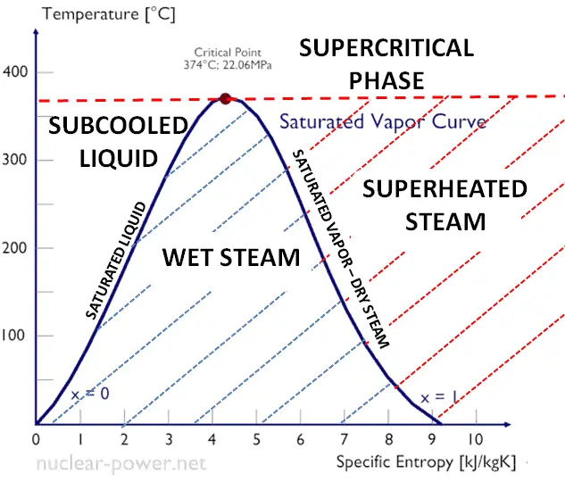
Superheated vapor or superheated steam is a vapor at a temperature higher than its boiling point at the absolute pressure where the temperature is measured.
Reheat allows to deliver more of the heat at a temperature close to the peak of the cycle. This requires the addition of another type of heat exchanger called a reheater. The use of the reheater involves splitting the turbine, i.e. use of a multistage turbine with a reheater. It was observed that more than two stages of reheating are unnecessary, since the next stage increases the cycle efficiency only half as much as the preceding stage.
High pressure and low pressure stages of the turbine are usually on the same shaft to drive a common generator, but they have separate cases. With a reheater, the flow is extracted after a partial expansion (point D), run back through the heat exchanger to heat it back up to the peak temperature (point E), and then passed to the low-pressure turbine. The expansion is then completed in the low-pressure turbine from point E to point F.

In the superheater, further heating at fixed pressure results in increases in both temperature and specific volume. The process of superheating of water vapor in the T-s diagram is provided in the figure between state E and saturation vapor curve. As can be seen also wet steam turbines (e.g. used in nuclear power plants) use superheated steam especially at the inlet of low-pressure stages. Typically most of nuclear power plants operates multi-stage condensing wet steam turbines (the high pressure stage runs on saturated steam). In these turbines the high-pressure stage receives steam (this steam is nearly saturated steam – x = 0.995 – point C at the figure) from a steam generator and exhaust it to moisture separator-reheater (point D). The steam must be reheated or superheated in order to avoid damages that could be caused to blades of steam turbine by low quality steam. High content of water droplets can cause the rapid impingement and erosion of the blades which occurs when condensed water is blasted onto the blades. To prevent this, condensate drains are installed in the steam piping leading to the turbine. The reheater heats the steam (point D) and then the steam is directed to the low-pressure stage of steam turbine, where expands (point E to F). The exhausted steam is at a pressure well below atmospheric, and, as can be seen from the picture, the steam is in a partially condensed state (point F), typically of a quality near 90%, but it is much higher vapor quality, than that it would be without reheat. Accordingly, superheating also tends to alleviate the problem of low vapor quality at the turbine exhaust.
Since the temperature of the primary coolant is limited by the pressure inside the reactor, superheaters (except a moisture separator reheater) are not used in nuclear power plants and they operate usually a single wet steam turbine.
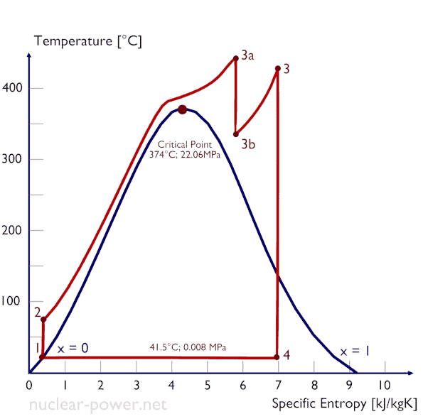
As was discussed the thermal efficiency can be improved “simply” by an increase in the temperature of the steam entering the turbine. But this temperature is restricted by metallurgical limitations imposed by the materials and design of the reactor pressure vessel and primary piping. The reactor vessel and the primary piping must withstand high pressures and great stresses at elevated temperatures. But currently, improved materials and methods of fabrication have permitted significant increases in the maximum pressures, with corresponding increases in thermal efficiency. The thermal power plants are currently designed to operate on the supercritical Rankine cycle (i.e. with steam pressures exceeding the critical pressure of water 22.1 MPa, and turbine inlet temperatures exceeding 600 °C). Supercritical fossil fuel power plants, that are operated at supercritical pressure, have efficiencies around 43%. Most efficient and also very complex coal-fired power plants that are operated at “ultra critical” pressures (i.e. around 30 MPa) and use multiple stage reheat reach about 48% efficiency.
Supercritical Water Reactor – SCWR
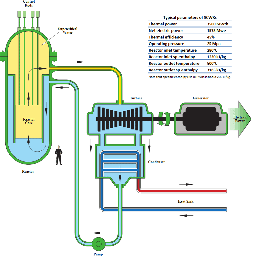
Supercritical Rankine cycle is also the thermodynamic cycle of supercritical water reactors. The supercritical water reactor (SCWR) is a concept of Generation IV reactor, that is operated at supercritical pressure (i.e. greater than 22.1 MPa). The term supercritical in this context refers to the thermodynamic critical point of water (TCR = 374 °C; pCR = 22.1 MPa), and must not be confused with the criticality of the reactor core, that describes changes in the neutron population in the reactor core.
For SCWRs a once through steam cycle has been envisaged, omitting any coolant recirculation inside the reactor. It is similar as in boiling water reactors, steam will be supplied directly to the steam turbine and the feed water from the steam cycle will be supplied back to the core.
As well as the supercritical water reactor may use light water or heavy water as neutron moderator. As can be seen, there are many SCWR designs, but all SCWRs have a key feature, that is the use of water beyond the thermodynamic critical point as primary coolant. Since this feature allows to increase the peak temperature, the supercritical water reactors are considered a promising advancement for nuclear power plants because of its high thermal efficiency (~45 % vs. ~33 % for current LWRs).
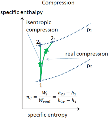
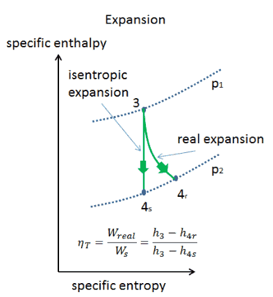
Isentropic Efficiency – Turbine, Pump
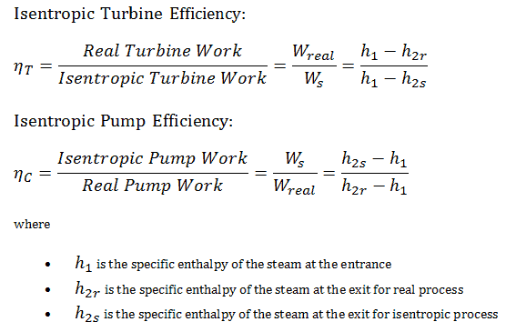
In previous chapters we assumed that the steam expansion is isentropic and therefore we used T4,is as the outlet temperature of the gas. These assumptions are only applicable with ideal cycles.
Most steady-flow devices (turbines, compressors, nozzles) operate under adiabatic conditions, but they are not truly isentropic but are rather idealized as isentropic for calculation purposes. We define parameters ηT, ηP, ηN, as a ratio of real work done by device to work by device when operated under isentropic conditions (in case of turbine). This ratio is known as the Isentropic Turbine/Pump/Nozzle Efficiency. These parameters describe how efficiently a turbine, compressor or nozzle approximates a corresponding isentropic device. This parameter reduces the overall efficiency and work output. For turbines, the value of ηT is typically 0.7 to 0.9 (70–90%).
See also: Isentropic Process
Rankine Cycle – Problem with Solution
Calculate:
- the vapor quality of the outlet steam
- the enthalpy difference between these two states (3 → 4), which corresponds to the work done by the steam, WT.
- the enthalpy difference between these two states (1 → 2), which corresponds to the work done by pumps, WP.
- the enthalpy difference between these two states (2 → 3), which corresponds to the net heat added in the steam generator
- the thermodynamic efficiency of this cycle and compare this value with the Carnot’s efficiency
1)
Since we do not know the exact vapor quality of the outlet steam, we have to determine this parameter. State 4 is fixed by the pressure p4 = 0.008 MPa and the fact that the specific entropy is constant for the isentropic expansion (s3 = s4 = 5.89 kJ/kgK for 6 MPa). The specific entropy of saturated liquid water (x=0) and dry steam (x=1) can be picked from steam tables. In case of wet steam, the actual entropy can be calculated with the vapor quality, x, and the specific entropies of saturated liquid water and dry steam:
s4 = sv x + (1 – x ) sl
where
s4 = entropy of wet steam (J/kg K) = 5.89 kJ/kgK
sv = entropy of “dry” steam (J/kg K) = 8.227 kJ/kgK (for 0.008 MPa)
sl = entropy of saturated liquid water (J/kg K) = 0.592 kJ/kgK (for 0.008 MPa)
From this equation the vapor quality is:
x4 = (s4 – sl) / (sv – sl) = (5.89 – 0.592) / (8.227 – 0.592) = 0.694 = 69.4%
2)
The enthalpy for the state 3 can be picked directly from steam tables, whereas the enthalpy for the state 4 must be calculated using vapor quality:
h3, v = 2785 kJ/kg
h4, wet = h4,v x + (1 – x ) h4,l = 2576 . 0.694 + (1 – 0.694) . 174 = 1787 + 53.2 = 1840 kJ/kg
Then the work done by the steam, WT, is
WT = Δh = 945 kJ/kg
3)
Enthalpy for state 1 can be picked directly from steam tables:
h1, l = 174 kJ/kg
State 2 is fixed by the pressure p2 = 6.0 MPa and the fact that the specific entropy is constant for the isentropic compression (s1 = s2 = 0.592 kJ/kgK for 0.008 MPa). For this entropy s2 = 0.592 kJ/kgK and p2 = 6.0 MPa we find h2, subcooled in steam tables for compressed water (using interpolation between two states).
h2, subcooled = 179.7 kJ/kg
Then the work done by the pumps, WP, is
WP = Δh = 5.7 kJ/kg
4)
The enthalpy difference between (2 → 3), which corresponds to the net heat added in the steam generator, is simply:
Qadd = h3, v – h2, subcooled = 2785 – 179.7 = 2605.3 kJ/kg
Note that, there is no heat regeneration in this cycle. On the other hand most of the heat added is for the enthalpy of vaporization (i.e. for the phase change).
5)
In this case, steam generators, steam turbine, condensers and feedwater pumps constitute a heat engine, that is subject to the efficiency limitations imposed by the second law of thermodynamics. In the ideal case (no friction, reversible processes, perfect design), this heat engine would have a Carnot efficiency of
ηCarnot = 1 – Tcold/Thot = 1 – 315/549 = 42.6%
where the temperature of the hot reservoir is 275.6°C (548.7 K), the temperature of the cold reservoir is 41.5°C (314.7K).
The thermodynamic efficiency of this cycle can be calculated by the following formula:
thus
ηth = (945 – 5.7) / 2605.3 = 0.361 = 36.1%
We hope, this article, Turbine Generator – Power Conversion System, helps you. If so, give us a like in the sidebar. Main purpose of this website is to help the public to learn some interesting and important information about thermal engineering.