Facebook Instagram Youtube Twitter

What is Hydraulic Lift Force – Definition

Analysis of the hydraulic lift force is one of the most important analysis in designing a fuel assembly and analyzing the hydraulic compatibility of mixed cores. Thermal Engineering

Drag Force in Nuclear Engineering

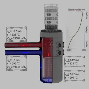
Analysis of the hydraulic lift force is one of the most important analysis in designing a fuel assembly and analyzing the hydraulic compatibility of mixed cores. The vertical forces are induced by upward high-velocity flow through the reactor core. The flow path for the reactor coolant through the reactor vessel would be:

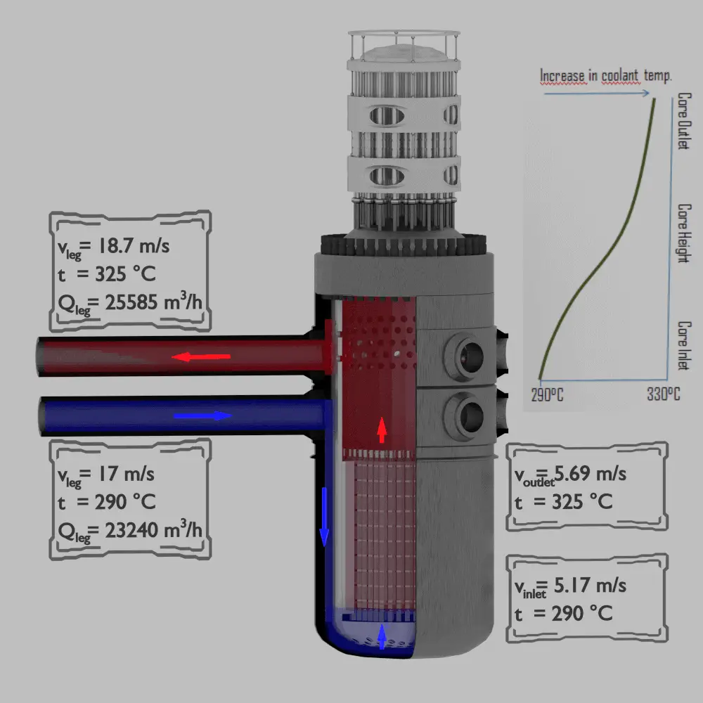
  • Continuity Equation - Flow Rates through Reactor
    Example of flow rates in a reactor. It is an illustrative example, data do not represent any reactor design.

    The coolant enters the reactor vessel at the inlet nozzle and hits against the core barrel.

  • The core barrel forces the water to flow downward in the space between the reactor vessel wall and the core barrel, this space is usually known as the downcomer.
  • From the bottom of the pressure vessel, the flow is reversed up through the core in order to pass through the fuel assemblies, where the coolant temperature increases as it passes through the fuel rods.
  • Finally the hotter reactor coolant enters the upper internals region, where it is routed out the outlet nozzle into the hot legs of primary circuit and goes on to the steam generators.
Fuel assemblies are held by the upper guide structure assembly, which defines the top of the core. This assembly is made of stainless steel and has many purposes. The upper guide structure assembly exerts an axial force on fuel assemblies (through springs in the top nozzle), thus defines the exact position of the fuel assembly in the core. The upper guide structure assembly flange is held in place and preloaded by the RPV closure head flange. The upper guide structure assembly also guides and protects control rod assemblies and in-core instrumentation.

Required downforce of the upper guide structure assembly on fuel assemblies must very carefully calculated. Insufficient downforce can result in the lift of the fuel assembly, on the other hand, an excessive downforce can result in bowing of fuel assembly, which is also unacceptable.

What is Drag in Physics

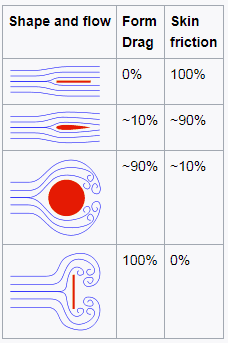
In fluid dynamics, drag is a force acting opposite to the relative motion of any moving object. The force a flowing fluid exerts on a body in the flow direction. Unlike other resistive forces, such as dry friction, which are nearly independent of velocity, drag forces depend on velocity. Drag force is proportional to the velocity for a laminar flow and the squared velocity for a turbulent flow. Drag is generally caused by two phenomena:

  • Drag - skin friction and form drag
    Source: wikipedia.org License: CC BY-SA 3.0

    Skin Friction.  In general, when a fluid flows over a stationary surface, e.g. the flat plate, the bed of a river, or the wall of a pipe, the fluid touching the surface is brought to rest by the shear stress to at the wall. The region in which flow adjusts from zero velocity at the wall to a maximum in the main stream of the flow is termed the boundary layer. Therefore, a moving fluid exerts tangential shear forces on the surface because of the no-slip condition caused by viscous effects.  This type of drag force, depends especially on the geometry, the roughness of the solid surface and on the type of fluid flow.

  • Form Drag. Form drag known also as pressure drag arises because of the shape and size of the object. This type of drag force is an interesting consequence the Bernoulli’s effect. According to Bernoulli’s principle, faster moving air exerts less pressure. This causes, that there can be a pressure difference between surfaces of the object. The general size and shape of the body are the most important factors in form drag. In general, bodies with a larger presented geometric cross-section will have a higher drag than thinner bodies.

Both of these forces, in general, have components in the direction of flow, and thus the resulting drag force is due to the combined effects of pressure and skin friction forces in the flow direction.

When the friction and pressure drag coefficients are available, the total drag coefficient is determined by simply adding them:

skin friction - form drag - coefficients

At low Reynolds numbers, most drag is due to friction drag. This is especially the case for highly streamlined bodies such as airfoils. On the other hand, at high Reynolds number, the pressure drop is significant, which increases form drag.

The components of the pressure and skin friction forces in the normal direction to flow tend to move the body in that direction, and their sum is called lift.

In aeronautics, the lift is an upward-acting force on an aircraft wing or airfoil. Bernoulli’s principle requires airfoil to be of an asymmetrical shape.

Drag Force – Drag Equation

The drag force, FD,depends on the density of the fluid, the upstream velocity, and the size, shape, and orientation of the body, among other things. One way to express this is by means of the drag equation. The drag equation is a formula used to calculate the drag force experienced by an object due to movement through a fluid.
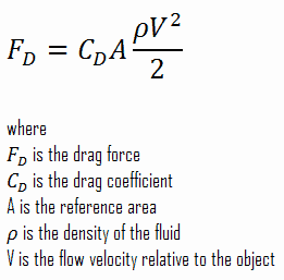
drag force - drag equation - formula

The reference area, A, is defined as the area of the orthographic projection of the object on a plane perpendicular to the direction of motion. For hollow objects, the reference area may be significantly larger than the cross sectional area, but for non-hollow objects, it is exactly the same as a cross sectional area.

Example: Drag Force – Drag Coefficient – Fuel Bundle
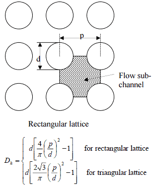
Hydraulic Diameter - Fuel ChannelCalculate the friction drag of a single fuel rod inside a reactor core at normal operation (design flow rate). Assume that this fuel rod is part of a fuel bundle with the rectangular fuel lattice and this fuel bundle does not contain spacing grids. Its height is h = 4m and the core flow velocity is constant and equal to Vcore = 5 m/s.

Assume that:

  • the outer diameter of the cladding is: d = 2 x rZr,1 = 9,3 mm
  • the pitch of fuel pins is: p = 13 mm
  • the relative roughness is ε/D = 5×10⁻⁴
  • the fluid density is: ρ = 714 kg/m3
  • the core flow velocity is constant and equal to Vcore = 5 m/s
  • the average temperature of reactor coolant is: Tbulk = 296°C

Calculation of the Reynolds number

To calculate the Reynolds number, we have to know:

  • the outer diameter of the cladding is: d = 2 x rZr,1 = 9,3 mm (to calculate the hydraulic diameter)
  • the pitch of fuel pins is: p = 13 mm  (to calculate the hydraulic diameter)
  • the dynamic viscosity of saturated water at 300°C is: μ = 0.0000859 N.s/m2
  • the fluid density is: ρ = 714 kg/m3

The hydraulic diameter, Dh, is a commonly used term when handling flow in non-circular tubes and channels. The hydraulic diameter of the fuel channel, Dh, is equal to 13,85 mm.

See also: Hydraulic Diameter

The Reynolds number inside the fuel channel is then equal to:

reynolds number - example

This fully satisfies the turbulent conditions.

Calculation of the Skin Friction Coefficient

The friction factor for turbulent flow depends strongly on the relative roughness. It is determined by the Colebrook equation or can be determined using the Moody chart. The Moody chart for Re = 575 600 and ε/D = 5 x 10⁻⁴ returns following values:

Therefore the skin friction coefficient is equal to:
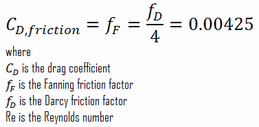
skin friction coefficient - example

Calculation of the Drag Force

To calculate the drag force, we have to know:

  • the skin friction coefficient, which is: CD,friction = 0.00425
  • the area of pin surface, which is: A = π.d.h = 0.1169 m2
  • the fluid density, which is: ρ = 714 kg/m3
  • the core flow velocity, which is constant and equal to Vcore = 5 m/s

From the skin friction coefficient, which is equal to the Fanning friction factor we can calculate the frictional component of the drag force. The drag force is given by:

drag force - example

Assuming that a fuel assembly can have, for example, 289 fuel pins (17×17 fuel assembly), the frictional component of the drag force is then of the order of kilonewtons. Moreover, this drag force originates purely from the skin friction on fuel bundle. But typical PWR fuel assembly contains another components, which influence the fuel assembly hydraulics:

  • Fuel rods. Fuel rods contain the fuel and burnable poisons.
  • Top nozzle. Provides the mechanical support for the fuel assembly structure.
  • Bottom nozzle. Provides the mechanical support for the fuel assembly structure.
  • Spacing grid. Ensures an exact guiding of the fuel rods.
  • Guide thimble tube. Vacant tube for control rods or in-core instrumentation.

As was written, the second component of the drag force is the form drag. Form drag known also as pressure drag arises because of the shape and size of the object. The pressure drag is proportional to the difference between the pressures acting on the front and back of the immersed body, and the frontal area.

Pressure Drop – Fuel Assembly

In general, total fuel assembly pressure drop is formed by fuel bundle frictional drop (dependent on relative roughness of fuel rods, reynolds number, hydraulic diameter etc.) and other pressure drops of structural elements (top and bottom nozzle, spacing grids or mixing grids).

In general, it is not so simple to calculate pressure drops in fuel assemblies (especially the spacing grids) and it belongs to key know-how of certain fuel manufacturer. Mostly, pressure drops are measured in experimental hydraulic loops, rather than calculated.

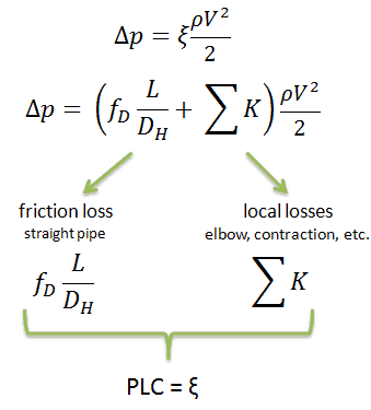
Engineers use the pressure loss coefficient, PLC. It is noted K or ξ  (pronounced “xi”). This coefficient characterizes pressure loss of a certain hydraulic system or of a part of a hydraulic system. It can be easily measured in hydraulic loops. The pressure loss coefficient can be defined or measured for both straight pipes and especially for local (minor) losses.
PLC - Pressure loss coefficient - equations

Using data from above mentioned example, the pressure loss coefficient (only frictional from straight pipe) is equal to ξ = fDL/DH = 4.9. But the overall pressure loss coefficient (including spacing grids, top and bottom nozzles etc.) is usually about three times higher. This PLC (ξ = 4.9) causes that the pressure drop is of the order of (using the previous inputs) Δpfriction =  4.9 x 714 x 52/ 2 = 43.7 kPa (without spacing grids, top and bottom nozzles). About three times higher real PLC means about three times higher Δpfuel will be.

The overall reactor pressure loss, Δpreactor, must include:

  • downcomer and reactor bottom
  • lower support plate
  • fuel assembly including spacing grids, top and bottom nozzles and other structural components – Δpfuel
  • upper guide structure assembly

In result the overall reactor pressure loss – Δpreactor is usually of the order of hundreds kPa (let say 300 – 400 kPa) for design parameters.

 
References:
Reactor Physics and Thermal Hydraulics:
  1. J. R. Lamarsh, Introduction to Nuclear Reactor Theory, 2nd ed., Addison-Wesley, Reading, MA (1983).
  2. J. R. Lamarsh, A. J. Baratta, Introduction to Nuclear Engineering, 3d ed., Prentice-Hall, 2001, ISBN: 0-201-82498-1.
  3. W. M. Stacey, Nuclear Reactor Physics, John Wiley & Sons, 2001, ISBN: 0- 471-39127-1.
  4. Glasstone, Sesonske. Nuclear Reactor Engineering: Reactor Systems Engineering, Springer; 4th edition, 1994, ISBN: 978-0412985317
  5. Todreas Neil E., Kazimi Mujid S. Nuclear Systems Volume I: Thermal Hydraulic Fundamentals, Second Edition. CRC Press; 2 edition, 2012, ISBN: 978-0415802871
  6. Zohuri B., McDaniel P. Thermodynamics in Nuclear Power Plant Systems. Springer; 2015, ISBN: 978-3-319-13419-2
  7. Moran Michal J., Shapiro Howard N. Fundamentals of Engineering Thermodynamics, Fifth Edition, John Wiley & Sons, 2006, ISBN: 978-0-470-03037-0
  8. Kleinstreuer C. Modern Fluid Dynamics. Springer, 2010, ISBN 978-1-4020-8670-0.
  9. U.S. Department of Energy, THERMODYNAMICS, HEAT TRANSFER, AND FLUID FLOW. DOE Fundamentals Handbook, Volume 1, 2 and 3. June 1992.
  10. White Frank M., Fluid Mechanics, McGraw-Hill Education, 7th edition, February, 2010, ISBN: 978-0077422417

See also:

Nuclear Fuel

We hope, this article, Hydraulic Lift Force, helps you. If so, give us a like in the sidebar. Main purpose of this website is to help the public to learn some interesting and important information about thermal engineering.

What is Pressure Drop – Fuel Assembly – Definition

Pressure Drop – Fuel Assembly. In general, total fuel assembly pressure drop is formed by fuel bundle frictional drop and other pressure drops of structural elements

Pressure Drop – Fuel Assembly

In general, total fuel assembly pressure drop is formed by fuel bundle frictional drop (dependent on relative roughness of fuel rods, reynolds number, hydraulic diameter etc.) and other pressure drops of structural elements (top and bottom nozzle, spacing grids or mixing grids).

See also: Fluid Acceleration – Pressure Loss

In general, it is not so simple to calculate pressure drops in fuel assemblies (especially the spacing grids) and it belongs to key know-how of certain fuel manufacturer. Mostly, pressure drops are measured in experimental hydraulic loops, rather than calculated.

Engineers use the pressure loss coefficient, PLC. It is noted K or ξ  (pronounced “xi”). This coefficient characterizes pressure loss of a certain hydraulic system or of a part of a hydraulic system. It can be easily measured in hydraulic loops. The pressure loss coefficient can be defined or measured for both straight pipes and especially for local (minor) losses.

PLC - Pressure loss coefficient - equations

Using data from below mentioned example, the pressure loss coefficient (only frictional from straight pipe) is equal to ξ = fDL/DH = 4.9. But the overall pressure loss coefficient (including spacing grids, top and bottom nozzles etc.) is usually about three times higher. This PLC (ξ = 4.9) causes that the pressure drop is of the order of (using the previous inputs) Δpfriction =  4.9 x 714 x 52/ 2 = 43.7 kPa (without spacing grids, top and bottom nozzles). About three times higher real PLC means about three times higher Δpfuel will be.

The overall reactor pressure loss, Δpreactor, must include:

  • downcomer and reactor bottom
  • lower support plate
  • fuel assembly including spacing grids, top and bottom nozzles and other structural components – Δpfuel
  • upper guide structure assembly

In result the overall reactor pressure loss – Δpreactor is usually of the order of hundreds kPa (let say 300 – 400 kPa) for design parameters.

It is an illustrative example, previous data do not correspond to any reactor design.

Example: Frictional Pressure Loss – Fuel Bundle

Hydraulic Diameter - Fuel ChannelCalculate the frictional pressure loss of a single fuel rod inside a reactor core at normal operation (design flow rate). Assume that this fuel rod is part of a fuel bundle with the rectangular fuel lattice and this fuel bundle does not contain spacing grids. Its height is h = 4m and the core flow velocity is constant and equal to Vcore = 5 m/s.

Assume that:

  • the outer diameter of the cladding is: d = 2 x rZr,1 = 9,3 mm
  • the pitch of fuel pins is: p = 13 mm
  • the relative roughness is ε/D = 5×10⁻⁴
  • the fluid density is: ρ = 714 kg/m3
  • the core flow velocity is constant and equal to Vcore = 5 m/s
  • the average temperature of reactor coolant is: Tbulk = 296°C

Calculation of the Reynolds number

To calculate the Reynolds number, we have to know:

  • the outer diameter of the cladding is: d = 2 x rZr,1 = 9,3 mm (to calculate the hydraulic diameter)
  • the pitch of fuel pins is: p = 13 mm  (to calculate the hydraulic diameter)
  • the dynamic viscosity of saturated water at 300°C is: μ = 0.0000859 N.s/m2
  • the fluid density is: ρ = 714 kg/m3

The hydraulic diameter, Dh, is a commonly used term when handling flow in non-circular tubes and channels. The hydraulic diameter of the fuel channel, Dh, is equal to 13,85 mm.

See also: Hydraulic Diameter

The Reynolds number inside the fuel channel is then equal to:

reynolds number - example

This fully satisfies the turbulent conditions.

Calculation of the Darcy Friction Factor

The friction factor for turbulent flow depends strongly on the relative roughness. It is determined by the Colebrook equation or can be determined using the Moody chart. The Moody chart for Re = 575 600 and ε/D = 5 x 10⁻⁴ returns following values:

Therefore, the pressure loss coefficient (only frictional from straight pipe) is equal to ξ = fDL/DH = 4.9.

 
References:
Reactor Physics and Thermal Hydraulics:
  1. J. R. Lamarsh, Introduction to Nuclear Reactor Theory, 2nd ed., Addison-Wesley, Reading, MA (1983).
  2. J. R. Lamarsh, A. J. Baratta, Introduction to Nuclear Engineering, 3d ed., Prentice-Hall, 2001, ISBN: 0-201-82498-1.
  3. W. M. Stacey, Nuclear Reactor Physics, John Wiley & Sons, 2001, ISBN: 0- 471-39127-1.
  4. Glasstone, Sesonske. Nuclear Reactor Engineering: Reactor Systems Engineering, Springer; 4th edition, 1994, ISBN: 978-0412985317
  5. Todreas Neil E., Kazimi Mujid S. Nuclear Systems Volume I: Thermal Hydraulic Fundamentals, Second Edition. CRC Press; 2 edition, 2012, ISBN: 978-0415802871
  6. Zohuri B., McDaniel P. Thermodynamics in Nuclear Power Plant Systems. Springer; 2015, ISBN: 978-3-319-13419-2
  7. Moran Michal J., Shapiro Howard N. Fundamentals of Engineering Thermodynamics, Fifth Edition, John Wiley & Sons, 2006, ISBN: 978-0-470-03037-0
  8. Kleinstreuer C. Modern Fluid Dynamics. Springer, 2010, ISBN 978-1-4020-8670-0.
  9. U.S. Department of Energy, THERMODYNAMICS, HEAT TRANSFER, AND FLUID FLOW. DOE Fundamentals Handbook, Volume 1, 2 and 3. June 1992.
  10. White Frank M., Fluid Mechanics, McGraw-Hill Education, 7th edition, February, 2010, ISBN: 978-0077422417

See also:

Nuclear Fuel

We hope, this article, Pressure Drop – Fuel Assembly, helps you. If so, give us a like in the sidebar. Main purpose of this website is to help the public to learn some interesting and important information about thermal engineering.

What is Liquid Metal – Definition

What is Liquid Metal. In reactor engineering, liquid metals are alloys with low melting point allowing for reactor coolant to be liquid in operating range of temperatures

What is Liquid Metal

In physics, liquid metal consists of alloy with very low melting points which form a eutectic that is liquid at room temperature. In reactor engineering, liquid metals are alloys with low melting point allowing for reactor coolant to be liquid in operating range of temperatures (usually above the room temperature).

thermal vs. fast reactor neutron spectrum
The spectrum of neutron energies produced by fission vary significantly with certain reactor design. thermal vs. fast reactor neutron spectrum

Liquid metals can be used as a reactor coolant because they have excellent heat transfer properties and can be employed in low-pressure systems as is the case of sodium-cooled fast reactors (SFRs). The unique feature of metals as far as their structure is concerned is the presence of charge carriers, specifically free electrons, giving them high electrical conductivity, high thermal conductivity. The use of liquid metal coolants made it possible to provide high rate of heat transfer in power plants as well as the temperatures of working surfaces of their constructions close to coolant temperature.

Moreover, liquid metals used in reactor engineering are very weak absorbers of neutrons allowing for liquid metal reactors to operate with fast neutron spectrum. A liquid metal fast reactor is a high power density reactor, which does not need neutron moderator.

The main differences between thermal and fast reactors are, of course, in neutron cross-sections, that exhibit significant energy dependency. It can be characterized by capture-to-fission ratio, which is lower in fast reactors. There is also a difference in the number of neutrons produced per one fission, which is higher in fast reactors than in thermal reactors. These very important differences are caused primarily by differences in neutron fluxes. Therefore it is very important to know detailed neutron energy distribution in a reactor core.

The disadvantage of many liquid metals is also their high chemical activity at interaction with oxygen, water and structural materials, which may cause heat transfer deterioration in the plant under certain conditions.

 
Conversion Factor for Fast Reactors
As was written, the conversion factor in a light water reactor is about 0.5, i.e. the production of new nuclear fuel is much less than its consumption. This is caused, among other things, by the relatively low value of the neutron yield factor. For a fast neutron spectrum, there are differences in both the number of neutrons produced per one fission and, of course, in the capture-to-fission ratio, which is lower for fast reactors. The number of neutrons produced per one fission is also higher in fast reactors than in thermal reactors. These two features are of importance in the neutron economy and contributes to the fact the fast reactors have a large excess of neutrons in the core. The breeding ratio in these reactors can vary over a rather wide range, depending on the neutron energy spectrum. A large breeding ratio favors a hard neutron spectrum. The superior neutron economy of a fast neutron reactor makes it possible to build a reactor that, after its initial fuel charge of plutonium, requires only natural (or even depleted) uranium feedstock as input to its fuel cycle. Russian BN-350 liquid-metal-cooled reactor was operated with a breeding ratio of over 1.2.

Sodium and NaK – Reactor Coolant

Sodium-cooled fast reactors (SFRs) are the most common fast reactor design. They use molten sodium or a eutectic sodium-potassium alloy (NaK) as the reactor coolant. Melting and boiling points of sodium and NaK are:

  • sodium-potassium alloy- eutectic
    Source: wikipedia.org License: Public domain

    sodium

    • melting point – 97.72°C
    • boiling point – 883°C
  • NaK – eutectic mixture
    • melting point – (-12°C)
    • boiling point – 785°C
Sodium-cooled Fast Reactor (SFR).
Source: wikipedia.org

NaK containing 40% to 90% potassium by weight is liquid at room temperature. The eutectic mixture consists of 77% potassium and 23% sodium. Sodium and NaK do not corrode steel to any significant degree and are compatible with many nuclear fuels, allowing for a wide choice of structural materials. Because sodium reacts violently with water, however, SFRs require the placement of an intermediate heat exchanger between the reactor core and the steam generator. This hi-tech technology requires a lot of experience, therefore only few countries have developed their own fast reactor design.

Lead and Lead-bismuth Eutectic – Reactor Coolant

Lead, lead-bismuth eutectic, and other metals have also been proposed and occasionally used. The lead-cooled fast reactor is a nuclear reactor design that features a fast neutron spectrum and molten lead or lead-bismuth eutectic coolant. Lead-Bismuth Eutectic or LBE is a eutectic alloy of lead (44.5%) and bismuth (55.5%). Molten lead or lead-bismuth eutectic can be used as the primary coolant because lead and bismuth have low neutron absorption and relatively low melting points.

Melting and boiling points of lead and lead-bismuth eutectic mixture are:

  • lead
    • melting point – 327.5°C
    • boiling point – 1749°C
  • lead-bismuth – eutectic mixture
    • melting point – 123.5°C
    • boiling point – 1670°C
Lead-cooled Fast Reactor (LFR)
Lead-cooled Fast Reactor (LFR).
Source: wikipedia.org

As compared to sodium-based liquid metal coolants such as liquid sodium or NaK, lead-based coolants have significantly higher boiling points, meaning a reactor can be operated without risk of coolant boiling at much higher temperatures. Lead and LBE also do not react readily with water or air, in contrast to sodium and NaK which ignite spontaneously in air and react explosively with water. Due to its denseness and high atomic number, lead and bismuth are also an excellent gamma radiation shield, while simultaneously being virtually transparent to neutrons.

On the other hand, lead and LBE coolant are more corrosive to steel than sodium or NaK eutectic alloy. This and the very high density of lead puts an upper limit on the velocity of coolant flow through the reactor due to safety considerations. Furthermore, the higher melting points of lead and LBE (327 °C and 123.5 °C respectively) may mean that solidification of the coolant may be a greater problem when the reactor is operated at lower temperatures.

Nusselt Number for Liquid Metal Reactors

A liquid metal cooled reactor is an advanced type of nuclear reactor where the primary coolant is a liquid metal.  Liquid metals can be used as a coolant because they have excellent heat transfer properties and can be employed in low-pressure systems as is the case of sodium-cooled fast reactors (SFRs). The unique feature of metals as far as their structure is concerned is the presence of charge carriers, specifically free electrons, giving them high electrical conductivity, high thermal conductivity. This very high thermal conductivity together with low viscosity causes, that typical heat transfer correlations (e.g. Dittus-Boelter) can not be used.

 
Thermal Conductivity of Sodium
Liquid sodium is used as a heat transfer fluid in some types of nuclear reactors because it has the high thermal conductivity and low neutron absorption cross section required to achieve a high neutron flux in the reactor. The high thermal conductivity properties effectively create a reservoir of heat capacity which provides thermal inertia against overheating.

thermal conductivity - sodium

See also: Thermal Conductivity

See also: Thermal Conductivity of Metals

Special reference: Thermophysical Properties of Materials For Nuclear Engineering: A Tutorial and Collection of Data. IAEA-THPH, IAEA, Vienna, 2008. ISBN 978–92–0–106508–7.

For liquid metals the Prandtl number is very small, generally in the range from 0.01 to 0.001. This means that the thermal diffusivity, which is related to the rate of heat transfer by conduction, unambiguously dominates. This very high thermal diffusivity results from very high thermal conductivity of metals, which is about 100 times higher than that of water. The Prandtl number for sodium at a typical operating temperature in the Sodium-cooled fast reactors is about 0.004. For this case the thermal boundary layer development is much more rapid than that of the velocity boundary layer (δt >> δ), and it is reasonable to assume uniform velocity throughout the thermal boundary layer.

Heat transfer coefficients for sodium flow through fuel channel are based on the Prandtl number and Péclet number. Pitch-to-diameter (P/D) also enters many calculations of heat transfer in liquid metal reactors. Convective heat transfer correlations are usually presented in terms of Nusselt number versus Péclet number. Typical Péclet number for normal operation are from 150 to 300 in the fuel bundles. As for another flow regimes,  the Nusselt number and a given correlation can be used to determine the convective heat transfer coefficient.

Graber-Rieger Correlation

Nusselt number - Liquid Metal - Graber-Rieger

FFTF Correlation

Nusselt number - Liquid Metal - FFTF

In 2003 the Generation IV International Forum (GIF) representing ten countries announced the selection of six reactor technologies which they believe represent the future shape of nuclear energy. These were selected on the basis of being clean, safe and cost-effective means of meeting increased energy. Two of promising designs of Generation IV reactors use a liquid metal as the reactor coolant. The development of Generation IV reactors represents a challenge from an engineering point of view.
  • Sodium-cooled fast reactor
  • Lead-cooled fast reactor

One of the main challenges in numerical simulation is the reliable modeling of heat transfer in liquid-metal cooled reactors by Computational Fluid Dynamics (CFD). Heat transfer applications with low-Prandtl number fluids are often in the transition range between conduction and convection dominated regimes.

 
References:
Reactor Physics and Thermal Hydraulics:
  1. J. R. Lamarsh, Introduction to Nuclear Reactor Theory, 2nd ed., Addison-Wesley, Reading, MA (1983).
  2. J. R. Lamarsh, A. J. Baratta, Introduction to Nuclear Engineering, 3d ed., Prentice-Hall, 2001, ISBN: 0-201-82498-1.
  3. W. M. Stacey, Nuclear Reactor Physics, John Wiley & Sons, 2001, ISBN: 0- 471-39127-1.
  4. Glasstone, Sesonske. Nuclear Reactor Engineering: Reactor Systems Engineering, Springer; 4th edition, 1994, ISBN: 978-0412985317
  5. Todreas Neil E., Kazimi Mujid S. Nuclear Systems Volume I: Thermal Hydraulic Fundamentals, Second Edition. CRC Press; 2 edition, 2012, ISBN: 978-0415802871
  6. Zohuri B., McDaniel P. Thermodynamics in Nuclear Power Plant Systems. Springer; 2015, ISBN: 978-3-319-13419-2
  7. Moran Michal J., Shapiro Howard N. Fundamentals of Engineering Thermodynamics, Fifth Edition, John Wiley & Sons, 2006, ISBN: 978-0-470-03037-0
  8. Kleinstreuer C. Modern Fluid Dynamics. Springer, 2010, ISBN 978-1-4020-8670-0.
  9. U.S. Department of Energy, THERMODYNAMICS, HEAT TRANSFER, AND FLUID FLOW. DOE Fundamentals Handbook, Volume 1, 2 and 3. June 1992.
  10. White Frank M., Fluid Mechanics, McGraw-Hill Education, 7th edition, February, 2010, ISBN: 978-0077422417

See also:

Materials

We hope, this article, Liquid Metal, helps you. If so, give us a like in the sidebar. Main purpose of this website is to help the public to learn some interesting and important information about thermal engineering.

What is Main Property of Liquid Metals – Definition

Properties of Liquid Metals. Liquid metals used in reactor engineering are very weak absorbers of neutrons. They have high thermal conductivity and high electrical conductivity. Thermal Engineering

Properties of Liquid Metals

Properties of Liquid Metals

In physics, liquid metal consists of alloy with very low melting points which form a eutectic that is liquid at room temperature. In reactor engineering, liquid metals are alloys with low melting point allowing for reactor coolant to be liquid in operating range of temperatures (usually above the room temperature).

thermal vs. fast reactor neutron spectrum
The spectrum of neutron energies produced by fission vary significantly with certain reactor design. thermal vs. fast reactor neutron spectrum

Liquid metals can be used as a reactor coolant because they have excellent heat transfer properties and can be employed in low-pressure systems as is the case of sodium-cooled fast reactors (SFRs). The unique feature of metals as far as their structure is concerned is the presence of charge carriers, specifically free electrons, giving them high electrical conductivity, high thermal conductivity. The use of liquid metal coolants made it possible to provide high rate of heat transfer in power plants as well as the temperatures of working surfaces of their constructions close to coolant temperature.

Moreover, liquid metals used in reactor engineering are very weak absorbers of neutrons allowing for liquid metal reactors to operate with fast neutron spectrum. A liquid metal fast reactor is a high power density reactor, which does not need neutron moderator.

The main differences between thermal and fast reactors are, of course, in neutron cross-sections, that exhibit significant energy dependency. It can be characterized by capture-to-fission ratio, which is lower in fast reactors. There is also a difference in the number of neutrons produced per one fission, which is higher in fast reactors than in thermal reactors. These very important differences are caused primarily by differences in neutron fluxes. Therefore it is very important to know detailed neutron energy distribution in a reactor core.

The disadvantage of many liquid metals is also their high chemical activity at interaction with oxygen, water and structural materials, which may cause heat transfer deterioration in the plant under certain conditions.

 
Conversion Factor for Fast Reactors
As was written, the conversion factor in a light water reactor is about 0.5, i.e. the production of new nuclear fuel is much less than its consumption. This is caused, among other things, by the relatively low value of the neutron yield factor. For a fast neutron spectrum, there are differences in both the number of neutrons produced per one fission and, of course, in the capture-to-fission ratio, which is lower for fast reactors. The number of neutrons produced per one fission is also higher in fast reactors than in thermal reactors. These two features are of importance in the neutron economy and contributes to the fact the fast reactors have a large excess of neutrons in the core. The breeding ratio in these reactors can vary over a rather wide range, depending on the neutron energy spectrum. A large breeding ratio favors a hard neutron spectrum. The superior neutron economy of a fast neutron reactor makes it possible to build a reactor that, after its initial fuel charge of plutonium, requires only natural (or even depleted) uranium feedstock as input to its fuel cycle. Russian BN-350 liquid-metal-cooled reactor was operated with a breeding ratio of over 1.2.

Sodium and NaK – Reactor Coolant

Sodium-cooled fast reactors (SFRs) are the most common fast reactor design. They use molten sodium or a eutectic sodium-potassium alloy (NaK) as the reactor coolant. Melting and boiling points of sodium and NaK are:

  • sodium-potassium alloy- eutectic
    Source: wikipedia.org License: Public domain

    sodium

    • melting point – 97.72°C
    • boiling point – 883°C
  • NaK – eutectic mixture
    • melting point – (-12°C)
    • boiling point – 785°C
Sodium-cooled Fast Reactor (SFR).
Source: wikipedia.org

NaK containing 40% to 90% potassium by weight is liquid at room temperature. The eutectic mixture consists of 77% potassium and 23% sodium. Sodium and NaK do not corrode steel to any significant degree and are compatible with many nuclear fuels, allowing for a wide choice of structural materials. Because sodium reacts violently with water, however, SFRs require the placement of an intermediate heat exchanger between the reactor core and the steam generator. This hi-tech technology requires a lot of experience, therefore only few countries have developed their own fast reactor design.

Lead and Lead-bismuth Eutectic – Reactor Coolant

Lead, lead-bismuth eutectic, and other metals have also been proposed and occasionally used. The lead-cooled fast reactor is a nuclear reactor design that features a fast neutron spectrum and molten lead or lead-bismuth eutectic coolant. Lead-Bismuth Eutectic or LBE is a eutectic alloy of lead (44.5%) and bismuth (55.5%). Molten lead or lead-bismuth eutectic can be used as the primary coolant because lead and bismuth have low neutron absorption and relatively low melting points.

Melting and boiling points of lead and lead-bismuth eutectic mixture are:

  • lead
    • melting point – 327.5°C
    • boiling point – 1749°C
  • lead-bismuth – eutectic mixture
    • melting point – 123.5°C
    • boiling point – 1670°C
Lead-cooled Fast Reactor (LFR)
Lead-cooled Fast Reactor (LFR).
Source: wikipedia.org

As compared to sodium-based liquid metal coolants such as liquid sodium or NaK, lead-based coolants have significantly higher boiling points, meaning a reactor can be operated without risk of coolant boiling at much higher temperatures. Lead and LBE also do not react readily with water or air, in contrast to sodium and NaK which ignite spontaneously in air and react explosively with water. Due to its denseness and high atomic number, lead and bismuth are also an excellent gamma radiation shield, while simultaneously being virtually transparent to neutrons.

On the other hand, lead and LBE coolant are more corrosive to steel than sodium or NaK eutectic alloy. This and the very high density of lead puts an upper limit on the velocity of coolant flow through the reactor due to safety considerations. Furthermore, the higher melting points of lead and LBE (327 °C and 123.5 °C respectively) may mean that solidification of the coolant may be a greater problem when the reactor is operated at lower temperatures.

Nusselt Number for Liquid Metal Reactors

A liquid metal cooled reactor is an advanced type of nuclear reactor where the primary coolant is a liquid metal.  Liquid metals can be used as a coolant because they have excellent heat transfer properties and can be employed in low-pressure systems as is the case of sodium-cooled fast reactors (SFRs). The unique feature of metals as far as their structure is concerned is the presence of charge carriers, specifically free electrons, giving them high electrical conductivity, high thermal conductivity. This very high thermal conductivity together with low viscosity causes, that typical heat transfer correlations (e.g. Dittus-Boelter) can not be used.

 
Thermal Conductivity of Sodium
Liquid sodium is used as a heat transfer fluid in some types of nuclear reactors because it has the high thermal conductivity and low neutron absorption cross section required to achieve a high neutron flux in the reactor. The high thermal conductivity properties effectively create a reservoir of heat capacity which provides thermal inertia against overheating.

thermal conductivity - sodium

See also: Thermal Conductivity

See also: Thermal Conductivity of Metals

Special reference: Thermophysical Properties of Materials For Nuclear Engineering: A Tutorial and Collection of Data. IAEA-THPH, IAEA, Vienna, 2008. ISBN 978–92–0–106508–7.

For liquid metals the Prandtl number is very small, generally in the range from 0.01 to 0.001. This means that the thermal diffusivity, which is related to the rate of heat transfer by conduction, unambiguously dominates. This very high thermal diffusivity results from very high thermal conductivity of metals, which is about 100 times higher than that of water. The Prandtl number for sodium at a typical operating temperature in the Sodium-cooled fast reactors is about 0.004. For this case the thermal boundary layer development is much more rapid than that of the velocity boundary layer (δt >> δ), and it is reasonable to assume uniform velocity throughout the thermal boundary layer.

Heat transfer coefficients for sodium flow through fuel channel are based on the Prandtl number and Péclet number. Pitch-to-diameter (P/D) also enters many calculations of heat transfer in liquid metal reactors. Convective heat transfer correlations are usually presented in terms of Nusselt number versus Péclet number. Typical Péclet number for normal operation are from 150 to 300 in the fuel bundles. As for another flow regimes,  the Nusselt number and a given correlation can be used to determine the convective heat transfer coefficient.

Graber-Rieger Correlation

Nusselt number - Liquid Metal - Graber-Rieger

FFTF Correlation

Nusselt number - Liquid Metal - FFTF

 
References:
Reactor Physics and Thermal Hydraulics:
  1. J. R. Lamarsh, Introduction to Nuclear Reactor Theory, 2nd ed., Addison-Wesley, Reading, MA (1983).
  2. J. R. Lamarsh, A. J. Baratta, Introduction to Nuclear Engineering, 3d ed., Prentice-Hall, 2001, ISBN: 0-201-82498-1.
  3. W. M. Stacey, Nuclear Reactor Physics, John Wiley & Sons, 2001, ISBN: 0- 471-39127-1.
  4. Glasstone, Sesonske. Nuclear Reactor Engineering: Reactor Systems Engineering, Springer; 4th edition, 1994, ISBN: 978-0412985317
  5. Todreas Neil E., Kazimi Mujid S. Nuclear Systems Volume I: Thermal Hydraulic Fundamentals, Second Edition. CRC Press; 2 edition, 2012, ISBN: 978-0415802871
  6. Zohuri B., McDaniel P. Thermodynamics in Nuclear Power Plant Systems. Springer; 2015, ISBN: 978-3-319-13419-2
  7. Moran Michal J., Shapiro Howard N. Fundamentals of Engineering Thermodynamics, Fifth Edition, John Wiley & Sons, 2006, ISBN: 978-0-470-03037-0
  8. Kleinstreuer C. Modern Fluid Dynamics. Springer, 2010, ISBN 978-1-4020-8670-0.
  9. U.S. Department of Energy, THERMODYNAMICS, HEAT TRANSFER, AND FLUID FLOW. DOE Fundamentals Handbook, Volume 1, 2 and 3. June 1992.
  10. White Frank M., Fluid Mechanics, McGraw-Hill Education, 7th edition, February, 2010, ISBN: 978-0077422417

See also:

Liquid Metals

We hope, this article, Main Property of Liquid Metals, helps you. If so, give us a like in the sidebar. Main purpose of this website is to help the public to learn some interesting and important information about thermal engineering.

What is Sodium and NaK – Reactor Coolant – Definition

Sodium-cooled fast reactors (SFRs) are the most common fast reactor design. They use molten sodium or a eutectic sodium-potassium alloy (NaK) as the reactor coolant. Thermal Engineering

Sodium and NaK – Reactor Coolant

Sodium-cooled fast reactors (SFRs) are the most common fast reactor design. They use molten sodium or a eutectic sodium-potassium alloy (NaK) as the reactor coolant. Melting and boiling points of sodium and NaK are:

  • sodium-potassium alloy- eutectic
    Source: wikipedia.org License: Public domain

    sodium

    • melting point – 97.72°C
    • boiling point – 883°C
  • NaK – eutectic mixture
    • melting point – (-12°C)
    • boiling point – 785°C
Sodium-cooled Fast Reactor (SFR).
Source: wikipedia.org

NaK containing 40% to 90% potassium by weight is liquid at room temperature. The eutectic mixture consists of 77% potassium and 23% sodium. Sodium and NaK do not corrode steel to any significant degree and are compatible with many nuclear fuels, allowing for a wide choice of structural materials. Because sodium reacts violently with water, however, SFRs require the placement of an intermediate heat exchanger between the reactor core and the steam generator. This hi-tech technology requires a lot of experience, therefore only few countries have developed their own fast reactor design.

Properties of Liquid Metals

Properties of Liquid Metals

In physics, liquid metal consists of alloy with very low melting points which form a eutectic that is liquid at room temperature. In reactor engineering, liquid metals are alloys with low melting point allowing for reactor coolant to be liquid in operating range of temperatures (usually above the room temperature).

thermal vs. fast reactor neutron spectrum
The spectrum of neutron energies produced by fission vary significantly with certain reactor design. thermal vs. fast reactor neutron spectrum

Liquid metals can be used as a reactor coolant because they have excellent heat transfer properties and can be employed in low-pressure systems as is the case of sodium-cooled fast reactors (SFRs). The unique feature of metals as far as their structure is concerned is the presence of charge carriers, specifically free electrons, giving them high electrical conductivity, high thermal conductivity. The use of liquid metal coolants made it possible to provide high rate of heat transfer in power plants as well as the temperatures of working surfaces of their constructions close to coolant temperature.

Moreover, liquid metals used in reactor engineering are very weak absorbers of neutrons allowing for liquid metal reactors to operate with fast neutron spectrum. A liquid metal fast reactor is a high power density reactor, which does not need neutron moderator.

The main differences between thermal and fast reactors are, of course, in neutron cross-sections, that exhibit significant energy dependency. It can be characterized by capture-to-fission ratio, which is lower in fast reactors. There is also a difference in the number of neutrons produced per one fission, which is higher in fast reactors than in thermal reactors. These very important differences are caused primarily by differences in neutron fluxes. Therefore it is very important to know detailed neutron energy distribution in a reactor core.

The disadvantage of many liquid metals is also their high chemical activity at interaction with oxygen, water and structural materials, which may cause heat transfer deterioration in the plant under certain conditions.

 
Conversion Factor for Fast Reactors
As was written, the conversion factor in a light water reactor is about 0.5, i.e. the production of new nuclear fuel is much less than its consumption. This is caused, among other things, by the relatively low value of the neutron yield factor. For a fast neutron spectrum, there are differences in both the number of neutrons produced per one fission and, of course, in the capture-to-fission ratio, which is lower for fast reactors. The number of neutrons produced per one fission is also higher in fast reactors than in thermal reactors. These two features are of importance in the neutron economy and contributes to the fact the fast reactors have a large excess of neutrons in the core. The breeding ratio in these reactors can vary over a rather wide range, depending on the neutron energy spectrum. A large breeding ratio favors a hard neutron spectrum. The superior neutron economy of a fast neutron reactor makes it possible to build a reactor that, after its initial fuel charge of plutonium, requires only natural (or even depleted) uranium feedstock as input to its fuel cycle. Russian BN-350 liquid-metal-cooled reactor was operated with a breeding ratio of over 1.2.

Nusselt Number for Liquid Metal Reactors

A liquid metal cooled reactor is an advanced type of nuclear reactor where the primary coolant is a liquid metal.  Liquid metals can be used as a coolant because they have excellent heat transfer properties and can be employed in low-pressure systems as is the case of sodium-cooled fast reactors (SFRs). The unique feature of metals as far as their structure is concerned is the presence of charge carriers, specifically free electrons, giving them high electrical conductivity, high thermal conductivity. This very high thermal conductivity together with low viscosity causes, that typical heat transfer correlations (e.g. Dittus-Boelter) can not be used.

 
Thermal Conductivity of Sodium
Liquid sodium is used as a heat transfer fluid in some types of nuclear reactors because it has the high thermal conductivity and low neutron absorption cross section required to achieve a high neutron flux in the reactor. The high thermal conductivity properties effectively create a reservoir of heat capacity which provides thermal inertia against overheating.

thermal conductivity - sodium

See also: Thermal Conductivity

See also: Thermal Conductivity of Metals

Special reference: Thermophysical Properties of Materials For Nuclear Engineering: A Tutorial and Collection of Data. IAEA-THPH, IAEA, Vienna, 2008. ISBN 978–92–0–106508–7.

For liquid metals the Prandtl number is very small, generally in the range from 0.01 to 0.001. This means that the thermal diffusivity, which is related to the rate of heat transfer by conduction, unambiguously dominates. This very high thermal diffusivity results from very high thermal conductivity of metals, which is about 100 times higher than that of water. The Prandtl number for sodium at a typical operating temperature in the Sodium-cooled fast reactors is about 0.004. For this case the thermal boundary layer development is much more rapid than that of the velocity boundary layer (δt >> δ), and it is reasonable to assume uniform velocity throughout the thermal boundary layer.

Heat transfer coefficients for sodium flow through fuel channel are based on the Prandtl number and Péclet number. Pitch-to-diameter (P/D) also enters many calculations of heat transfer in liquid metal reactors. Convective heat transfer correlations are usually presented in terms of Nusselt number versus Péclet number. Typical Péclet number for normal operation are from 150 to 300 in the fuel bundles. As for another flow regimes,  the Nusselt number and a given correlation can be used to determine the convective heat transfer coefficient.

Graber-Rieger Correlation

Nusselt number - Liquid Metal - Graber-Rieger

FFTF Correlation

Nusselt number - Liquid Metal - FFTF

 
References:
Reactor Physics and Thermal Hydraulics:
  1. J. R. Lamarsh, Introduction to Nuclear Reactor Theory, 2nd ed., Addison-Wesley, Reading, MA (1983).
  2. J. R. Lamarsh, A. J. Baratta, Introduction to Nuclear Engineering, 3d ed., Prentice-Hall, 2001, ISBN: 0-201-82498-1.
  3. W. M. Stacey, Nuclear Reactor Physics, John Wiley & Sons, 2001, ISBN: 0- 471-39127-1.
  4. Glasstone, Sesonske. Nuclear Reactor Engineering: Reactor Systems Engineering, Springer; 4th edition, 1994, ISBN: 978-0412985317
  5. Todreas Neil E., Kazimi Mujid S. Nuclear Systems Volume I: Thermal Hydraulic Fundamentals, Second Edition. CRC Press; 2 edition, 2012, ISBN: 978-0415802871
  6. Zohuri B., McDaniel P. Thermodynamics in Nuclear Power Plant Systems. Springer; 2015, ISBN: 978-3-319-13419-2
  7. Moran Michal J., Shapiro Howard N. Fundamentals of Engineering Thermodynamics, Fifth Edition, John Wiley & Sons, 2006, ISBN: 978-0-470-03037-0
  8. Kleinstreuer C. Modern Fluid Dynamics. Springer, 2010, ISBN 978-1-4020-8670-0.
  9. U.S. Department of Energy, THERMODYNAMICS, HEAT TRANSFER, AND FLUID FLOW. DOE Fundamentals Handbook, Volume 1, 2 and 3. June 1992.
  10. White Frank M., Fluid Mechanics, McGraw-Hill Education, 7th edition, February, 2010, ISBN: 978-0077422417

See also:

Liquid Metals

We hope, this article, Sodium and NaK – Reactor Coolant, helps you. If so, give us a like in the sidebar. Main purpose of this website is to help the public to learn some interesting and important information about thermal engineering.

What is Lead and Lead-bismuth Eutectic – Reactor Coolant – Definition

Lead, lead-bismuth eutectic, and other metals have also been proposed and occasionally used. The lead-cooled fast reactor is a nuclear reactor design that features a fast neutron spectrum. Thermal Engineering

Lead and Lead-bismuth Eutectic – Reactor Coolant

Lead, lead-bismuth eutectic, and other metals have also been proposed and occasionally used. The lead-cooled fast reactor is a nuclear reactor design that features a fast neutron spectrum and molten lead or lead-bismuth eutectic coolant. Lead-Bismuth Eutectic or LBE is a eutectic alloy of lead (44.5%) and bismuth (55.5%). Molten lead or lead-bismuth eutectic can be used as the primary coolant because lead and bismuth have low neutron absorption and relatively low melting points.

Melting and boiling points of lead and lead-bismuth eutectic mixture are:

  • lead
    • melting point – 327.5°C
    • boiling point – 1749°C
  • lead-bismuth – eutectic mixture
    • melting point – 123.5°C
    • boiling point – 1670°C
Lead-cooled Fast Reactor (LFR)
Lead-cooled Fast Reactor (LFR).
Source: wikipedia.org

As compared to sodium-based liquid metal coolants such as liquid sodium or NaK, lead-based coolants have significantly higher boiling points, meaning a reactor can be operated without risk of coolant boiling at much higher temperatures. Lead and LBE also do not react readily with water or air, in contrast to sodium and NaK which ignite spontaneously in air and react explosively with water. Due to its denseness and high atomic number, lead and bismuth are also an excellent gamma radiation shield, while simultaneously being virtually transparent to neutrons.

On the other hand, lead and LBE coolant are more corrosive to steel than sodium or NaK eutectic alloy. This and the very high density of lead puts an upper limit on the velocity of coolant flow through the reactor due to safety considerations. Furthermore, the higher melting points of lead and LBE (327 °C and 123.5 °C respectively) may mean that solidification of the coolant may be a greater problem when the reactor is operated at lower temperatures.

Properties of Liquid Metals

Properties of Liquid Metals

In physics, liquid metal consists of alloy with very low melting points which form a eutectic that is liquid at room temperature. In reactor engineering, liquid metals are alloys with low melting point allowing for reactor coolant to be liquid in operating range of temperatures (usually above the room temperature).

thermal vs. fast reactor neutron spectrum
The spectrum of neutron energies produced by fission vary significantly with certain reactor design. thermal vs. fast reactor neutron spectrum

Liquid metals can be used as a reactor coolant because they have excellent heat transfer properties and can be employed in low-pressure systems as is the case of sodium-cooled fast reactors (SFRs). The unique feature of metals as far as their structure is concerned is the presence of charge carriers, specifically free electrons, giving them high electrical conductivity, high thermal conductivity. The use of liquid metal coolants made it possible to provide high rate of heat transfer in power plants as well as the temperatures of working surfaces of their constructions close to coolant temperature.

Moreover, liquid metals used in reactor engineering are very weak absorbers of neutrons allowing for liquid metal reactors to operate with fast neutron spectrum. A liquid metal fast reactor is a high power density reactor, which does not need neutron moderator.

The main differences between thermal and fast reactors are, of course, in neutron cross-sections, that exhibit significant energy dependency. It can be characterized by capture-to-fission ratio, which is lower in fast reactors. There is also a difference in the number of neutrons produced per one fission, which is higher in fast reactors than in thermal reactors. These very important differences are caused primarily by differences in neutron fluxes. Therefore it is very important to know detailed neutron energy distribution in a reactor core.

The disadvantage of many liquid metals is also their high chemical activity at interaction with oxygen, water and structural materials, which may cause heat transfer deterioration in the plant under certain conditions.

 
Conversion Factor for Fast Reactors
As was written, the conversion factor in a light water reactor is about 0.5, i.e. the production of new nuclear fuel is much less than its consumption. This is caused, among other things, by the relatively low value of the neutron yield factor. For a fast neutron spectrum, there are differences in both the number of neutrons produced per one fission and, of course, in the capture-to-fission ratio, which is lower for fast reactors. The number of neutrons produced per one fission is also higher in fast reactors than in thermal reactors. These two features are of importance in the neutron economy and contributes to the fact the fast reactors have a large excess of neutrons in the core. The breeding ratio in these reactors can vary over a rather wide range, depending on the neutron energy spectrum. A large breeding ratio favors a hard neutron spectrum. The superior neutron economy of a fast neutron reactor makes it possible to build a reactor that, after its initial fuel charge of plutonium, requires only natural (or even depleted) uranium feedstock as input to its fuel cycle. Russian BN-350 liquid-metal-cooled reactor was operated with a breeding ratio of over 1.2.
 
References:
Reactor Physics and Thermal Hydraulics:
  1. J. R. Lamarsh, Introduction to Nuclear Reactor Theory, 2nd ed., Addison-Wesley, Reading, MA (1983).
  2. J. R. Lamarsh, A. J. Baratta, Introduction to Nuclear Engineering, 3d ed., Prentice-Hall, 2001, ISBN: 0-201-82498-1.
  3. W. M. Stacey, Nuclear Reactor Physics, John Wiley & Sons, 2001, ISBN: 0- 471-39127-1.
  4. Glasstone, Sesonske. Nuclear Reactor Engineering: Reactor Systems Engineering, Springer; 4th edition, 1994, ISBN: 978-0412985317
  5. Todreas Neil E., Kazimi Mujid S. Nuclear Systems Volume I: Thermal Hydraulic Fundamentals, Second Edition. CRC Press; 2 edition, 2012, ISBN: 978-0415802871
  6. Zohuri B., McDaniel P. Thermodynamics in Nuclear Power Plant Systems. Springer; 2015, ISBN: 978-3-319-13419-2
  7. Moran Michal J., Shapiro Howard N. Fundamentals of Engineering Thermodynamics, Fifth Edition, John Wiley & Sons, 2006, ISBN: 978-0-470-03037-0
  8. Kleinstreuer C. Modern Fluid Dynamics. Springer, 2010, ISBN 978-1-4020-8670-0.
  9. U.S. Department of Energy, THERMODYNAMICS, HEAT TRANSFER, AND FLUID FLOW. DOE Fundamentals Handbook, Volume 1, 2 and 3. June 1992.
  10. White Frank M., Fluid Mechanics, McGraw-Hill Education, 7th edition, February, 2010, ISBN: 978-0077422417

See also:

Liquid Metals

We hope, this article, Lead and Lead-bismuth Eutectic – Reactor Coolant, helps you. If so, give us a like in the sidebar. Main purpose of this website is to help the public to learn some interesting and important information about thermal engineering.

What is Nusselt Number for Liquid Metal Reactors – Definition

Nusselt Number for Liquid Metal Reactors. For Liquid metal reactors, convective heat transfer correlations are usually presented in terms of Nusselt number versus Péclet number. Thermal Engineering

Nusselt Number for Liquid Metal Reactors

A liquid metal cooled reactor is an advanced type of nuclear reactor where the primary coolant is a liquid metal.  Liquid metals can be used as a coolant because they have excellent heat transfer properties and can be employed in low-pressure systems as is the case of sodium-cooled fast reactors (SFRs). The unique feature of metals as far as their structure is concerned is the presence of charge carriers, specifically free electrons, giving them high electrical conductivity, high thermal conductivity. This very high thermal conductivity together with low viscosity causes, that typical heat transfer correlations (e.g. Dittus-Boelter) can not be used.

 
Thermal Conductivity of Sodium
Liquid sodium is used as a heat transfer fluid in some types of nuclear reactors because it has the high thermal conductivity and low neutron absorption cross section required to achieve a high neutron flux in the reactor. The high thermal conductivity properties effectively create a reservoir of heat capacity which provides thermal inertia against overheating.

thermal conductivity - sodium

See also: Thermal Conductivity

See also: Thermal Conductivity of Metals

Special reference: Thermophysical Properties of Materials For Nuclear Engineering: A Tutorial and Collection of Data. IAEA-THPH, IAEA, Vienna, 2008. ISBN 978–92–0–106508–7.

For liquid metals the Prandtl number is very small, generally in the range from 0.01 to 0.001. This means that the thermal diffusivity, which is related to the rate of heat transfer by conduction, unambiguously dominates. This very high thermal diffusivity results from very high thermal conductivity of metals, which is about 100 times higher than that of water. The Prandtl number for sodium at a typical operating temperature in the Sodium-cooled fast reactors is about 0.004. For this case the thermal boundary layer development is much more rapid than that of the velocity boundary layer (δt >> δ), and it is reasonable to assume uniform velocity throughout the thermal boundary layer.

Heat transfer coefficients for sodium flow through fuel channel are based on the Prandtl number and Péclet number. Pitch-to-diameter (P/D) also enters many calculations of heat transfer in liquid metal reactors. Convective heat transfer correlations are usually presented in terms of Nusselt number versus Péclet number. Typical Péclet number for normal operation are from 150 to 300 in the fuel bundles. As for another flow regimes,  the Nusselt number and a given correlation can be used to determine the convective heat transfer coefficient.

Graber-Rieger Correlation

Nusselt number - Liquid Metal - Graber-Rieger

FFTF Correlation

Nusselt number - Liquid Metal - FFTF

 
References:
Reactor Physics and Thermal Hydraulics:
  1. J. R. Lamarsh, Introduction to Nuclear Reactor Theory, 2nd ed., Addison-Wesley, Reading, MA (1983).
  2. J. R. Lamarsh, A. J. Baratta, Introduction to Nuclear Engineering, 3d ed., Prentice-Hall, 2001, ISBN: 0-201-82498-1.
  3. W. M. Stacey, Nuclear Reactor Physics, John Wiley & Sons, 2001, ISBN: 0- 471-39127-1.
  4. Glasstone, Sesonske. Nuclear Reactor Engineering: Reactor Systems Engineering, Springer; 4th edition, 1994, ISBN: 978-0412985317
  5. Todreas Neil E., Kazimi Mujid S. Nuclear Systems Volume I: Thermal Hydraulic Fundamentals, Second Edition. CRC Press; 2 edition, 2012, ISBN: 978-0415802871
  6. Zohuri B., McDaniel P. Thermodynamics in Nuclear Power Plant Systems. Springer; 2015, ISBN: 978-3-319-13419-2
  7. Moran Michal J., Shapiro Howard N. Fundamentals of Engineering Thermodynamics, Fifth Edition, John Wiley & Sons, 2006, ISBN: 978-0-470-03037-0
  8. Kleinstreuer C. Modern Fluid Dynamics. Springer, 2010, ISBN 978-1-4020-8670-0.
  9. U.S. Department of Energy, THERMODYNAMICS, HEAT TRANSFER, AND FLUID FLOW. DOE Fundamentals Handbook, Volume 1, 2 and 3. June 1992.
  10. White Frank M., Fluid Mechanics, McGraw-Hill Education, 7th edition, February, 2010, ISBN: 978-0077422417

See also:

Nusselt Number

We hope, this article, Nusselt Number for Liquid Metal Reactors, helps you. If so, give us a like in the sidebar. Main purpose of this website is to help the public to learn some interesting and important information about thermal engineering.

What is Dynamic Pressure – Velocity Pressure – Definition

Dynamic Pressure – Velocity Pressure. The term dynamic pressure (sometimes called velocity pressure) is associated with fluid flow and with the Bernoulli’s effect. Thermal Engineering

Dynamic Pressure – Velocity Pressure

In general, pressure is a measure of the force exerted per unit area on the boundaries of a substance. The term dynamic pressure (sometimes called velocity pressure)  is associated with fluid flow and with the Bernoulli’s effect, which is described by the Bernoulli’s equation:

Bernoulli Theorem - Equation

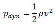
This effect causes the lowering of fluid pressure (static pressure) in regions where the flow velocity is increased. This lowering of pressure in a constriction of a flow path may seem counterintuitive, but seems less so when you consider pressure to be energy density. In the high velocity flow through the constriction, kinetic energy (dynamic pressure – ½.ρ.v2) must increase at the expense of pressure energy (static pressure – p).

As can be seen, dynamic pressure is dynamic pressure is one of the terms of Bernoulli’s equation. In incompressible fluid dynamics, dynamic pressure is the quantity defined by:

dynamic pressure - formula

The simplified form of Bernoulli’s equation can be summarized in the following memorable word equation:

static pressure + dynamic pressure = total pressure (stagnation pressure)

Total and dynamic pressure are not pressures in the usual sense – they cannot be measured using an aneroid, Bourdon tube or mercury column.

To avoid potential ambiguity when referring to pressure in fluid dynamics, many authors use the term static pressure to distinguish it from total pressure and dynamic pressure. The term static pressure is identical to the term pressure, and can be identified for every point in a fluid flow field. Dynamic pressure is the difference between stagnation pressure and static pressure.

Dynamic Pressure and Pressure Loss

PLC - Pressure loss coefficient - equationsDynamic pressure is closely related to pressure losses. In the practical analysis of piping systems the quantity of most importance is the pressure loss due to viscous effects along the length of the system, as well as additional pressure losses arising from other technological equipments like, valves, elbows, piping entrances, fittings and tees. By observation, the  head loss is roughly proportional to the square of the flow rate in most engineering flows (fully developed, turbulent pipe flow). In fact, the  head loss is directly proportional to the dynamic pressure.

The constant of proportionality is the pressure loss coefficient. The pressure loss coefficient is noted K or ξ  (pronounced “xi”). This coefficient characterizes pressure loss of a certain hydraulic system or of a part of a hydraulic system. It can be easily measured in hydraulic loops. The pressure loss coefficient can be defined or measured for both straight pipes and especially for local (minor) losses. For example, the pressure loss coefficient ξ = 4.9  causes that the pressure drop will be about 4.9 times the dynamic pressure.

 
References:
Heat Transfer:
  1. Fundamentals of Heat and Mass Transfer, 7th Edition. Theodore L. Bergman, Adrienne S. Lavine, Frank P. Incropera. John Wiley & Sons, Incorporated, 2011. ISBN: 9781118137253.
  2. Heat and Mass Transfer. Yunus A. Cengel. McGraw-Hill Education, 2011. ISBN: 9780071077866.
  3. Fundamentals of Heat and Mass Transfer. C. P. Kothandaraman. New Age International, 2006, ISBN: 9788122417722.
  4. U.S. Department of Energy, Thermodynamics, Heat Transfer and Fluid Flow. DOE Fundamentals Handbook, Volume 2 of 3. May 2016.

Nuclear and Reactor Physics:

  1. J. R. Lamarsh, Introduction to Nuclear Reactor Theory, 2nd ed., Addison-Wesley, Reading, MA (1983).
  2. J. R. Lamarsh, A. J. Baratta, Introduction to Nuclear Engineering, 3d ed., Prentice-Hall, 2001, ISBN: 0-201-82498-1.
  3. W. M. Stacey, Nuclear Reactor Physics, John Wiley & Sons, 2001, ISBN: 0- 471-39127-1.
  4. Glasstone, Sesonske. Nuclear Reactor Engineering: Reactor Systems Engineering, Springer; 4th edition, 1994, ISBN: 978-0412985317
  5. W.S.C. Williams. Nuclear and Particle Physics. Clarendon Press; 1 edition, 1991, ISBN: 978-0198520467
  6. G.R.Keepin. Physics of Nuclear Kinetics. Addison-Wesley Pub. Co; 1st edition, 1965
  7. Robert Reed Burn, Introduction to Nuclear Reactor Operation, 1988.
  8. U.S. Department of Energy, Nuclear Physics and Reactor Theory. DOE Fundamentals Handbook, Volume 1 and 2. January 1993.
  9. Paul Reuss, Neutron Physics. EDP Sciences, 2008. ISBN: 978-2759800414.

Advanced Reactor Physics:

  1. K. O. Ott, W. A. Bezella, Introductory Nuclear Reactor Statics, American Nuclear Society, Revised edition (1989), 1989, ISBN: 0-894-48033-2.
  2. K. O. Ott, R. J. Neuhold, Introductory Nuclear Reactor Dynamics, American Nuclear Society, 1985, ISBN: 0-894-48029-4.
  3. D. L. Hetrick, Dynamics of Nuclear Reactors, American Nuclear Society, 1993, ISBN: 0-894-48453-2.
  4. E. E. Lewis, W. F. Miller, Computational Methods of Neutron Transport, American Nuclear Society, 1993, ISBN: 0-894-48452-4.

See also:

Pressure

We hope, this article, Dynamic Pressure – Velocity Pressure, helps you. If so, give us a like in the sidebar. Main purpose of this website is to help the public to learn some interesting and important information about thermal engineering.
What is Stagnation Pressure – Pitot Pressure – Definition

Stagnation Pressure – Pitot Pressure. Stagnation pressure (or pitot pressure or total pressure) is the static pressure at a stagnation point in a fluid flow. Thermal Engineering

Stagnation Pressure – Pitot Pressure

In general, pressure is a measure of the force exerted per unit area on the boundaries of a substance. In fluid dynamics and aerodynamics, stagnation pressure (or pitot pressure or total pressure) is the static pressure at a stagnation point in a fluid flow. At a stagnation point the fluid velocity is zero and all kinetic energy has been converted into pressure energy (isentropically). This effect is widely used in aerodynamics (velocity measurement or ram-air intake).

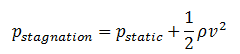
Stagnation pressure is equal to the sum of the free-stream dynamic pressure and free-stream static pressure.

stagnation pressure - total pressure

Static pressure and dynamic pressure are terms of Bernoulli’s equation:

Bernoulli Theorem - Equation

The Bernoulli’s effect causes the lowering of fluid pressure (static pressure – p) in regions where the flow velocity is increased. This lowering of pressure in a constriction of a flow path may seem counterintuitive, but seems less so when you consider pressure to be energy density. In the high velocity flow through the constriction, kinetic energy (dynamic pressure – ½.ρ.v2) must increase at the expense of pressure energy (static pressure – p).

The simplified form of Bernoulli’s equation can be summarized in the following memorable word equation:

static pressure + dynamic pressure = total pressure (stagnation pressure)

Total and dynamic pressure are not pressures in the usual sense – they cannot be measured using an aneroid, Bourdon tube or mercury column.

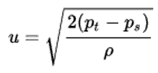
Stagnation pressure is sometimes referred to as pitot pressure because it is measured using a pitot tube. A Pitot tube is a pressure measurement instrument used to measure fluid flow velocity. Velocity can be determined using the following formula:

pitot tube - formula - velocity

where:

  • u is flow velocity to be measured in m/s,
  • ps is stagnation or total pressure in Pa,
  • pt is static pressure in Pa,
  • ρ is fluid density in kg/m3.
 
References:
Heat Transfer:
  1. Fundamentals of Heat and Mass Transfer, 7th Edition. Theodore L. Bergman, Adrienne S. Lavine, Frank P. Incropera. John Wiley & Sons, Incorporated, 2011. ISBN: 9781118137253.
  2. Heat and Mass Transfer. Yunus A. Cengel. McGraw-Hill Education, 2011. ISBN: 9780071077866.
  3. Fundamentals of Heat and Mass Transfer. C. P. Kothandaraman. New Age International, 2006, ISBN: 9788122417722.
  4. U.S. Department of Energy, Thermodynamics, Heat Transfer and Fluid Flow. DOE Fundamentals Handbook, Volume 2 of 3. May 2016.

Nuclear and Reactor Physics:

  1. J. R. Lamarsh, Introduction to Nuclear Reactor Theory, 2nd ed., Addison-Wesley, Reading, MA (1983).
  2. J. R. Lamarsh, A. J. Baratta, Introduction to Nuclear Engineering, 3d ed., Prentice-Hall, 2001, ISBN: 0-201-82498-1.
  3. W. M. Stacey, Nuclear Reactor Physics, John Wiley & Sons, 2001, ISBN: 0- 471-39127-1.
  4. Glasstone, Sesonske. Nuclear Reactor Engineering: Reactor Systems Engineering, Springer; 4th edition, 1994, ISBN: 978-0412985317
  5. W.S.C. Williams. Nuclear and Particle Physics. Clarendon Press; 1 edition, 1991, ISBN: 978-0198520467
  6. G.R.Keepin. Physics of Nuclear Kinetics. Addison-Wesley Pub. Co; 1st edition, 1965
  7. Robert Reed Burn, Introduction to Nuclear Reactor Operation, 1988.
  8. U.S. Department of Energy, Nuclear Physics and Reactor Theory. DOE Fundamentals Handbook, Volume 1 and 2. January 1993.
  9. Paul Reuss, Neutron Physics. EDP Sciences, 2008. ISBN: 978-2759800414.

Advanced Reactor Physics:

  1. K. O. Ott, W. A. Bezella, Introductory Nuclear Reactor Statics, American Nuclear Society, Revised edition (1989), 1989, ISBN: 0-894-48033-2.
  2. K. O. Ott, R. J. Neuhold, Introductory Nuclear Reactor Dynamics, American Nuclear Society, 1985, ISBN: 0-894-48029-4.
  3. D. L. Hetrick, Dynamics of Nuclear Reactors, American Nuclear Society, 1993, ISBN: 0-894-48453-2.
  4. E. E. Lewis, W. F. Miller, Computational Methods of Neutron Transport, American Nuclear Society, 1993, ISBN: 0-894-48452-4.

See also:

Pressure

We hope, this article, Stagnation Pressure – Pitot Pressure, helps you. If so, give us a like in the sidebar. Main purpose of this website is to help the public to learn some interesting and important information about thermal engineering.

What is Static Pressure – Definition

The term static pressure is identical to the term pressure, and can be identified for every point in a fluid flow field. Static pressure is one of the terms of Bernoulli’s equation

Static Pressure

In general, pressure is a measure of the force exerted per unit area on the boundaries of a substance. In fluid dynamics, many authors use the term static pressure in preference to just pressure to avoid ambiguity. The term static pressure is identical to the term pressure, and can be identified for every point in a fluid flow field.

Static pressure is one of the terms of Bernoulli’s equation:

Bernoulli Theorem - Equation

The Bernoulli’s effect causes the lowering of fluid pressure (static pressure – p) in regions where the flow velocity is increased. This lowering of pressure in a constriction of a flow path may seem counterintuitive, but seems less so when you consider pressure to be energy density. In the high velocity flow through the constriction, kinetic energy (dynamic pressure – ½.ρ.v2) must increase at the expense of pressure energy (static pressure – p).

The simplified form of Bernoulli’s equation can be summarized in the following memorable word equation:

static pressure + dynamic pressure = total pressure (stagnation pressure)

Total and dynamic pressure are not pressures in the usual sense – they cannot be measured using an aneroid, Bourdon tube or mercury column.

 
References:
Heat Transfer:
  1. Fundamentals of Heat and Mass Transfer, 7th Edition. Theodore L. Bergman, Adrienne S. Lavine, Frank P. Incropera. John Wiley & Sons, Incorporated, 2011. ISBN: 9781118137253.
  2. Heat and Mass Transfer. Yunus A. Cengel. McGraw-Hill Education, 2011. ISBN: 9780071077866.
  3. Fundamentals of Heat and Mass Transfer. C. P. Kothandaraman. New Age International, 2006, ISBN: 9788122417722.
  4. U.S. Department of Energy, Thermodynamics, Heat Transfer and Fluid Flow. DOE Fundamentals Handbook, Volume 2 of 3. May 2016.

Nuclear and Reactor Physics:

  1. J. R. Lamarsh, Introduction to Nuclear Reactor Theory, 2nd ed., Addison-Wesley, Reading, MA (1983).
  2. J. R. Lamarsh, A. J. Baratta, Introduction to Nuclear Engineering, 3d ed., Prentice-Hall, 2001, ISBN: 0-201-82498-1.
  3. W. M. Stacey, Nuclear Reactor Physics, John Wiley & Sons, 2001, ISBN: 0- 471-39127-1.
  4. Glasstone, Sesonske. Nuclear Reactor Engineering: Reactor Systems Engineering, Springer; 4th edition, 1994, ISBN: 978-0412985317
  5. W.S.C. Williams. Nuclear and Particle Physics. Clarendon Press; 1 edition, 1991, ISBN: 978-0198520467
  6. G.R.Keepin. Physics of Nuclear Kinetics. Addison-Wesley Pub. Co; 1st edition, 1965
  7. Robert Reed Burn, Introduction to Nuclear Reactor Operation, 1988.
  8. U.S. Department of Energy, Nuclear Physics and Reactor Theory. DOE Fundamentals Handbook, Volume 1 and 2. January 1993.
  9. Paul Reuss, Neutron Physics. EDP Sciences, 2008. ISBN: 978-2759800414.

Advanced Reactor Physics:

  1. K. O. Ott, W. A. Bezella, Introductory Nuclear Reactor Statics, American Nuclear Society, Revised edition (1989), 1989, ISBN: 0-894-48033-2.
  2. K. O. Ott, R. J. Neuhold, Introductory Nuclear Reactor Dynamics, American Nuclear Society, 1985, ISBN: 0-894-48029-4.
  3. D. L. Hetrick, Dynamics of Nuclear Reactors, American Nuclear Society, 1993, ISBN: 0-894-48453-2.
  4. E. E. Lewis, W. F. Miller, Computational Methods of Neutron Transport, American Nuclear Society, 1993, ISBN: 0-894-48452-4.

See also:

Pressure

We hope, this article, Static Pressure, helps you. If so, give us a like in the sidebar. Main purpose of this website is to help the public to learn some interesting and important information about thermal engineering.