Facebook Instagram Youtube Twitter

What is Four Stroke Diesel Engine – Definition

Diesel engines may be designed as either two stroke or four stroke cycles. In the four stroke Diesel engine, the piston travels along the cylinder four times. Thermal Engineering

Diesel Cycle – Diesel Engine

In the 1890s, a German inventor, Rudolf Diesel has patented his invention of an efficient, slow burning, compression ignition, internal combustion engine. The original cycle proposed by Rudolf Diesel was a constant temperature cycle. In later years Diesel realized his original cycle would not work and he adopted the constant pressure cycle, which is known as the Diesel cycle.

Diesel cycle is one of most common thermodynamic cycles that can be found in automobile engines and describes the functioning of a typical compression ignition piston engine. The Diesel engine is similar in operation to the gasoline engine. The most important difference is that:

  • There is no fuel in the cylinder at the beginning of the compression stroke, therefore an autoignition does not occur in Diesel engines.
  • Diesel engine uses compression ignition instead of spark ignition.
  • Because of the high temperature developed during the adiabatic compression, the fuel ignites spontaneously as it is injected. Therefore no spark plugs are needed.
  • Before the beginning of the power stroke, the injectors start to inject fuel directly into the combustion chamber and therefore first part of power stroke occurs approximately at the constant pressure.
  • Higher compression ratios can be achieved in Diesel engines, than in Otto engines
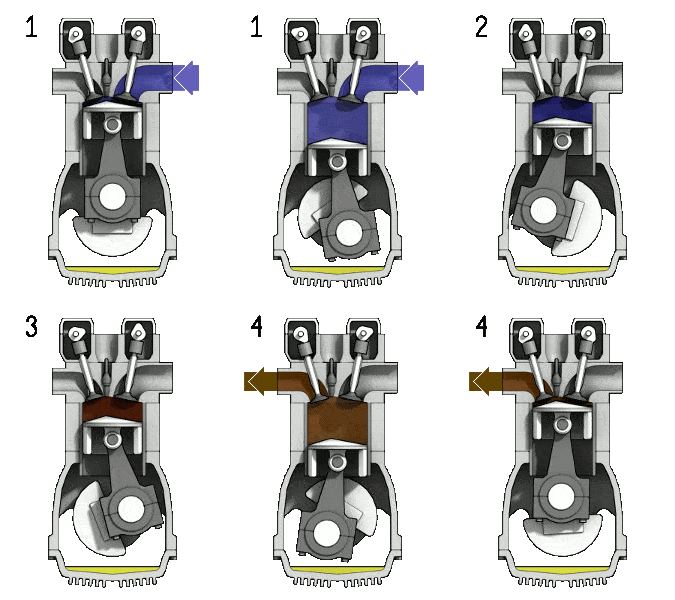
The Diesel engine is similar in operation to the gasoline engine. In this picture, there is an Otto engine, which is ignited by a spark plug instead of compression itself.
Four stroke engine - Otto engine
Four stroke engine – Otto engine
Source: wikipedia.org, Own work of Zephyris, CC BY-SA 3.0
In contrast to Otto cycle, the Diesel cycle does not execute isochoric heat addition. In an ideal Diesel cycle, the system executing the cycle undergoes a series of four processes: two isentropic (reversible adiabatic) processes alternated with one isochoric process and one isobaric process.

Since Carnot’s principle states that no engine can be more efficient than a reversible engine (a Carnot heat engine) operating between the same high temperature and low temperature reservoirs, the Diesel engine must have lower efficiency than the Carnot efficiency. A typical diesel automotive engine operates at around 30% to 35% of thermal efficiency. About 65-70% is rejected as waste heat without being converted into useful work, i.e. work delivered to wheels. In general, engines using the Diesel cycle are usually more efficient, than engines using the Otto cycle. The diesel engine has the highest thermal efficiency of any practical combustion engine. Low-speed diesel engines (as used in ships) can have a thermal efficiency that exceeds 50%. The largest diesel engine in the world peaks at 51.7%.

Four Stroke Diesel Engine

Diesel engines may be designed as either two stroke or four stroke cycles.The four stroke Diesel engine is an internal combustion (IC) engine in which the piston completes four separate strokes while turning a crankshaft. A stroke refers to the full travel of the piston along the cylinder, in either direction. Therefore each stroke does not correspond to single thermodynamic process given in chapter Diesel Cycle – Processes.

The four stroke engine comprises:

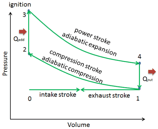
  • the intake stroke – The piston moves from top dead center (TDC) to bottom dead center (BDC) and the cycle passes points 0 → 1. In this stroke the intake valve is open while the piston pulls air (without a fuel) into the cylinder by producing vacuum pressure into the cylinder through its downward motion.
  • the compression stroke – The piston moves from bottom dead center (BDC) to top dead center (TDC) and the cycle passes points 1 → 2 . In this stroke both the intake and exhaust valves are closed, resulting in adiabatic air compression (i.e. without heat transfer to or from the environment). During this compression, the volume is reduced, the pressure and temperature both rise. At the end of this stroke fuel is injected and burns in the compressed hot air. At the end of this stroke the crankshaft has completed a full 360 degree revolution.
  • the power stroke – The piston moves from top dead center (TDC) to bottom dead center (BDC) and the cycle passes points 2 → 3 → 4. In this stroke both the intake and exhaust valves are closed. At the beginning of the power stroke, a near isobaric combustion occur between 2 and 3. In this interval the pressure remains constant since the piston descends, and the volume increases. At 3 fuel injection and combustion are complete, and the cylinder contains gas at a higher temperature than at 2. Between 3 and 4 this hot gas expands, again approximately adiabatically. In this stroke the piston is driven towards the crankshaft, the volume in increased, and the work is done by the gas on the piston.
  • the exhaust stroke. The piston moves from bottom dead center (BDC) to top dead center (TDC) and the cycle passes points 4 → 1 → 0. In this stroke the exhaust valve is open while the piston pulls an exhaust gases out of the chamber. At the end of this stroke the crankshaft has completed a second full 360 degree revolution.

Note that: In an ideal case, the adiabatic expansion should continue, until the pressure falls to that of the surrounding air. This would increase the thermal efficiency of such engine, but this also causes the practical difficulties with the engine. Simply the engine would have to be much larger.

Examples of Compression Ratios – Gasoline vs. Diesel

  • The compression ratio in a gasoline-powered engine will usually not be much higher than 10:1 due to potential engine knocking (autoignition) and not lower than 6:1.
  • A turbocharged Subaru Impreza WRX has a compression ratio of 8.0:1. In general, a turbocharged or supercharged engines already have compressed air at air intake, therefore they are usually built with lower compression ratio.
  • A stock Honda S2000 engine (F22C1) has a compression ratio of 11.1:1.
  • Some atmospheric sportscar engines can have compression ratio up to 12.5 : 1 (e.g. Ferrari 458 Italia).
  • In 2012, Mazda released new petrol engines under the brand name SkyActiv with a 14:1 compression ratio. To reduce the risk of engine knocking, residual gas is reduced by using 4-2-1 engine exhaust systems, implementing a piston cavity, and optimizing fuel injection.
  • The Diesel engines have the compression ratio that normally exceed 14:1 and ratios over 22:1 are also common.
 
References:
Nuclear and Reactor Physics:
  1. J. R. Lamarsh, Introduction to Nuclear Reactor Theory, 2nd ed., Addison-Wesley, Reading, MA (1983).
  2. J. R. Lamarsh, A. J. Baratta, Introduction to Nuclear Engineering, 3d ed., Prentice-Hall, 2001, ISBN: 0-201-82498-1.
  3. W. M. Stacey, Nuclear Reactor Physics, John Wiley & Sons, 2001, ISBN: 0- 471-39127-1.
  4. Glasstone, Sesonske. Nuclear Reactor Engineering: Reactor Systems Engineering, Springer; 4th edition, 1994, ISBN: 978-0412985317
  5. W.S.C. Williams. Nuclear and Particle Physics. Clarendon Press; 1 edition, 1991, ISBN: 978-0198520467
  6. Kenneth S. Krane. Introductory Nuclear Physics, 3rd Edition, Wiley, 1987, ISBN: 978-0471805533
  7. G.R.Keepin. Physics of Nuclear Kinetics. Addison-Wesley Pub. Co; 1st edition, 1965
  8. Robert Reed Burn, Introduction to Nuclear Reactor Operation, 1988.
  9. U.S. Department of Energy, Nuclear Physics and Reactor Theory. DOE Fundamentals Handbook, Volume 1 and 2. January 1993.

Advanced Reactor Physics:

  1. K. O. Ott, W. A. Bezella, Introductory Nuclear Reactor Statics, American Nuclear Society, Revised edition (1989), 1989, ISBN: 0-894-48033-2.
  2. K. O. Ott, R. J. Neuhold, Introductory Nuclear Reactor Dynamics, American Nuclear Society, 1985, ISBN: 0-894-48029-4.
  3. D. L. Hetrick, Dynamics of Nuclear Reactors, American Nuclear Society, 1993, ISBN: 0-894-48453-2.
  4. E. E. Lewis, W. F. Miller, Computational Methods of Neutron Transport, American Nuclear Society, 1993, ISBN: 0-894-48452-4.

Other References:

Diesel Engine – Car Recycling

See also:

Diesel Cycle

We hope, this article, Four Stroke Diesel Engine, helps you. If so, give us a like in the sidebar. Main purpose of this website is to help the public to learn some interesting and important information about thermal engineering.
What is Isothermal Curve – Isotherm – Definition

On a pV diagram, the process occurs along a line called isothermal curve or an isotherm. This curve has the equation p = constant / V. It can be derived from ideal gas law. Thermal Engineering

Isothermal Process

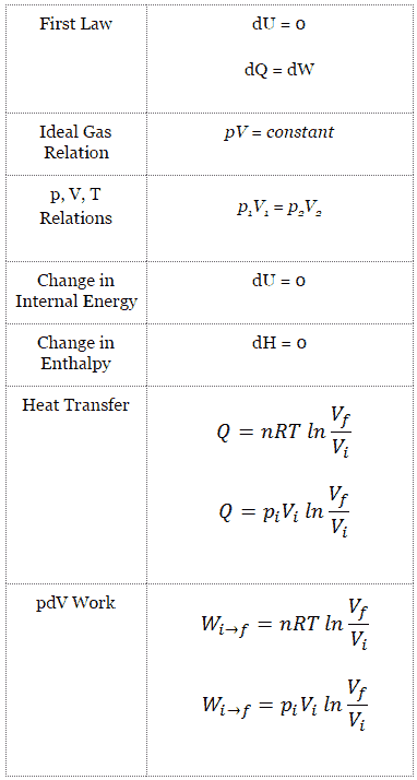
An isothermal process is a thermodynamic process, in which the temperature of the system remains constant (T = const). The heat transfer into or out of the system typically must happen at such a slow rate in order to continually adjust to the temperature of the reservoir through heat exchange. In each of these states the thermal equilibrium is maintained.

For an ideal gas and a polytropic process, the case n = 1 corresponds to an isothermal (constant-temperature) process. In contrast to adiabatic process , in which n = κ  and a system exchanges no heat with its surroundings (Q = 0; ∆T≠0), in an isothermal process there is no change in the internal energy (due to ∆T=0) and therefore ΔU = 0 (for ideal gases) and Q ≠ 0. An adiabatic process is not necessarily an isothermal process, nor is an isothermal process necessarily adiabatic.

In engineering, phase changes, such as evaporation or melting, are isothermal processes when, as is usually the case, they occur at constant pressure and temperature.

Isothermal process - main characteristics
Isothermal process – main characteristics
Boyle-Mariotte Law
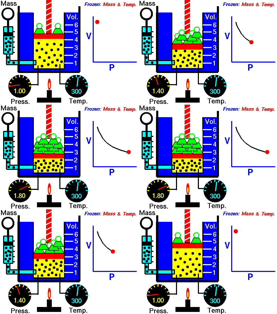
Boyle-Mariotte Law. For a fixed mass of gas at constant temperature, the volume is inversely proportional to the pressure. Source: grc.nasa.gov NASA copyright policy states that “NASA material is not protected by copyright unless noted”.

Isothermal Curve – Isotherm

On a pV diagram, the process occurs along a line called isothermal curve or an isotherm. This curve has the equation p = constant / V. It can be derived from ideal gas law.

isotherm curve - exampleIn an ideal gas, molecules have no volume and do not interact. According to the ideal gas law, pressure varies linearly with temperature and quantity, and inversely with volume.

pV = nRT

where:

  • p is the absolute pressure of the gas
  • n is the amount of substance
  • T is the absolute temperature
  • V is the volume
  • R  is the ideal, or universal, gas constant, equal to the product of the Boltzmann constant and the Avogadro constant,

In this equation the symbol R is a constant called the universal gas constant that has the same value for all gases—namely, R =  8.31 J/mol K.

The isothermal process can be expressed with the ideal gas law as:

pV = constant

and the isotherm can be expressed as:

p = constant / V

It corresponds to the Boyle-Mariotte Law, which states that:

For a fixed mass of gas at constant temperature, the volume is inversely proportional to the pressure.

Isothermal process - pV diagram
Isothermal process – pV diagram
 
References:
Nuclear and Reactor Physics:
  1. J. R. Lamarsh, Introduction to Nuclear Reactor Theory, 2nd ed., Addison-Wesley, Reading, MA (1983).
  2. J. R. Lamarsh, A. J. Baratta, Introduction to Nuclear Engineering, 3d ed., Prentice-Hall, 2001, ISBN: 0-201-82498-1.
  3. W. M. Stacey, Nuclear Reactor Physics, John Wiley & Sons, 2001, ISBN: 0- 471-39127-1.
  4. Glasstone, Sesonske. Nuclear Reactor Engineering: Reactor Systems Engineering, Springer; 4th edition, 1994, ISBN: 978-0412985317
  5. W.S.C. Williams. Nuclear and Particle Physics. Clarendon Press; 1 edition, 1991, ISBN: 978-0198520467
  6. Kenneth S. Krane. Introductory Nuclear Physics, 3rd Edition, Wiley, 1987, ISBN: 978-0471805533
  7. G.R.Keepin. Physics of Nuclear Kinetics. Addison-Wesley Pub. Co; 1st edition, 1965
  8. Robert Reed Burn, Introduction to Nuclear Reactor Operation, 1988.
  9. U.S. Department of Energy, Nuclear Physics and Reactor Theory. DOE Fundamentals Handbook, Volume 1 and 2. January 1993.

Advanced Reactor Physics:

  1. K. O. Ott, W. A. Bezella, Introductory Nuclear Reactor Statics, American Nuclear Society, Revised edition (1989), 1989, ISBN: 0-894-48033-2.
  2. K. O. Ott, R. J. Neuhold, Introductory Nuclear Reactor Dynamics, American Nuclear Society, 1985, ISBN: 0-894-48029-4.
  3. D. L. Hetrick, Dynamics of Nuclear Reactors, American Nuclear Society, 1993, ISBN: 0-894-48453-2.
  4. E. E. Lewis, W. F. Miller, Computational Methods of Neutron Transport, American Nuclear Society, 1993, ISBN: 0-894-48452-4.

See also:

Thermodynamic Processes

We hope, this article, Isothermal Curve – Isotherm, helps you. If so, give us a like in the sidebar. Main purpose of this website is to help the public to learn some interesting and important information about thermal engineering.

What is Isobaric Process – Definition

An isobaric process or a constant-pressure process is a thermodynamic process, in which the pressure of the system remains constant (p = const). Thermal Engineering

Isobaric Process

An isobaric process is a thermodynamic process, in which the pressure of the system remains constant (p = const). The heat transfer into or out of the system does work, but also changes the internal energy of the system.

Since there are changes in internal energy (dU) and changes in system volume (∆V), engineers often use the enthalpy of the system, which is defined as:

H = U + pV

In many thermodynamic analyses it is convenient to use the enthalpy instead of the internal energy. Especially in case of the first law of thermodynamics.

The enthalpy is the preferred expression of system energy that changes in many chemical, biological, and physical measurements at constant pressure. It is so useful that it is tabulated in the steam tables along with specific volume and specific internal energy. It is due to the fact, it simplifies the description of energy transfer. At constant pressure, the enthalpy change equals the energy transferred from the environment through heating (Q = H2 – H1) or work other than expansion work. For a variable-pressure process, the difference in enthalpy is not quite as obvious.

There are expressions in terms of more familiar variables such as temperature and pressure:

dH = CpdT + V(1-αT)dp

Where Cp is the heat capacity at constant pressure and α is the coefficient of (cubic) thermal expansion. For ideal gas αT = 1 and therefore:

dH = CpdT

For an ideal gas and a polytropic process, the case n = 0 corresponds to an isobaric (constant-pressure) process. In contrast to adiabatic process , in which n =  and a system exchanges no heat with its surroundings (Q = 0; ∆T≠0), in an isobaric process there is a change in the internal energy (due to ∆T≠0) and therefore ΔU ≠ 0 (for ideal gases) and Q ≠ 0.

In engineering, both very important thermodynamic cycles (Brayton and Rankine cycle) are based on two isobaric processes, therefore the study of this process is crucial for power plants.

Isobaric process - main characteristics
Isobaric process – main characteristics
Charles's Law is one of the gas laws.
For a fixed mass of gas at constant pressure, the volume is directly proportional to the Kelvin temperature. Source: grc.nasa.gov NASA copyright policy states that “NASA material is not protected by copyright unless noted”.

Isobaric Process and the First Law

The classical form of the first law of thermodynamics is the following equation:

dU = dQ – dW

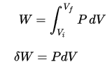
In this equation dW is equal to dW = pdV and is known as the boundary work.

In an isobaric process and the ideal gas, part of heat added to the system will be used to do work and part of heat added will increase the internal energy (increase the temperature).  Therefore it is convenient to use the enthalpy instead of the internal energy.Since H = U + pV, therefore dH = dU + pdV + Vdp and we substitute dU = dH – pdV – Vdp into the classical form of the law:

dH – pdV – Vdp = dQ – pdV

We obtain the law in terms of enthalpy:

dH = dQ + Vdp

or

dH = TdS + Vdp

In this equation the term Vdp is a flow process work. This work,  Vdp, is used for open flow systems like a turbine or a pump in which there is a “dp”, i.e. change in pressure. There are no changes in control volume. As can be seen, this form of the law simplifies the description of energy transfer. At constant pressure, the enthalpy change equals the energy transferred from the environment through heating:

Isobaric process (Vdp = 0):

dH = dQ     →     Q = H2 – H1

At constant entropy, i.e. in isentropic process, the enthalpy change equals the flow process work done on or by the system.

Isentropic process (dQ = 0):

dH = Vdp     →     W = H2 – H1

It is obvious, it will be very useful in analysis of both thermodynamic cycles used in power engineering, i.e. in Brayton cycle and Rankine cycle.

 
Example: Frictionless Piston – Heat – Enthalpy
Enthalpy - Example - A frictionless piston
Calculate the final temperature, if 3000 kJ of heat is added.

A frictionless piston is used to provide a constant pressure of 500 kPa in a cylinder containing steam (superheated steam) of a volume of 2 m3  at 500 K. Calculate the final temperature, if 3000 kJ of heat is added.

Solution:

Using steam tables we know, that the specific enthalpy of such steam (500 kPa; 500 K) is about 2912 kJ/kg. Since at this condition the steam has density of 2.2 kg/m3, then we know there is about 4.4 kg of steam in the piston at enthalpy of 2912 kJ/kg x 4.4 kg = 12812 kJ.

When we use simply Q = H2 − H1, then the resulting enthalpy of steam will be:

H2 = H1 + Q = 15812 kJ

From steam tables, such superheated steam (15812/4.4 = 3593 kJ/kg) will have a temperature of 828 K (555°C). Since at this enthalpy the steam have density of 1.31 kg/m3, it is obvious that it has expanded by about 2.2/1.31 = 1.67 (+67%). Therefore the resulting volume is 2 m3 x 1.67 = 3.34 m3 and ∆V = 3.34 m3 – 2 m3 = 1.34 m3.

The p∆V part of enthalpy, i.e. the work done is:

W = p∆V = 500 000 Pa x 1.34 m3 = 670 kJ

Isobaric Process – Ideal Gas Equation

See also: What is an Ideal Gas

isobaric process - work - pV diagram
On a p-V diagram, the process occurs along a horizontal line (called an isobar) that has the equation p = constant.

Let assume an isobaric heat addition in an ideal gas. In an ideal gas, molecules have no volume and do not interact. According to the ideal gas law, pressure varies linearly with temperature and quantity, and inversely with volume.

pV = nRT

where:

  • p is the absolute pressure of the gas
  • n is the amount of substance
  • T is the absolute temperature
  • V is the volume
  • R  is the ideal, or universal, gas constant, equal to the product of the Boltzmann constant and the Avogadro constant,

In this equation the symbol R is a constant called the universal gas constant that has the same value for all gases—namely, R =  8.31 J/mol K.

The isobaric process can be expressed with the ideal gas law as:

isobaric process - equation - 2

or

isobaric process - equation - 3

On a p-V diagram, the process occurs along a horizontal line (called an isobar) that has the equation p = constant.

Pressure-volume work by the closed system is defined as:

pV work - isobaric process

Assuming that the quantity of ideal gas remains constant and applying the ideal gas law, this becomes

isobaric process - work equation

According to the ideal gas model, the internal energy can be calculated by:

∆U = m cv ∆T

where the property cv (J/mol K) is referred to as specific heat (or heat capacity) at a constant volume because under certain special conditions (constant volume) it relates the temperature change of a system to the amount of energy added by heat transfer.

Adding these equations together, we obtain the equation for heat:

Q =  m cv ∆T + m R ∆T = m (cv +R)∆T = m cp ∆T

where the property cp (J/mol K) is referred to as specific heat (or heat capacity) at a constant pressure.

See also: Specific Heat at Constant Volume and Constant Pressure

See also: Mayer’s formula

Charles’s Law

Charles’s Law is one of the gas laws. At the end of the 18th century, a French inventor and scientist Jacques Alexandre César Charles studied the relationship between the volume and the temperature of a gas at constant pressure. The results of certain experiments with gases at relatively low pressure led Jacques Alexandre César Charles to formulate a well-known law. It states that:

For a fixed mass of gas at constant pressure, the volume is directly proportional to the Kelvin temperature.

That means that, for example, if you double the temperature, you will double the volume. If you halve the temperature, you will halve the volume.

You can express this mathematically as:

V = constant . T

Yes, it seems to be identical as isobaric process of ideal gas. These results are fully consistent with ideal gas law, which determinates, that the constant is equal to nR/p. If you rearrange the pV = nRT equation by dividing both sides by p, you will obtain:

V = nR/p  .  T

where nR/p is constant and:

  • p is the absolute pressure of the gas
  • n is the amount of substance
  • T is the absolute temperature
  • V is the volume
  • R  is the ideal, or universal, gas constant, equal to the product of the Boltzmann constant and the Avogadro constant,

In this equation the symbol R is a constant called the universal gas constant that has the same value for all gases—namely, R =  8.31 J/mol K.

Example of Isobaric Process – Isobaric Heat Addition

first law - example - brayton cycle
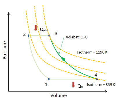
Ideal Brayton cycle consist of four thermodynamic processes. Two isentropic processes and two isobaric processes.

Let assume the ideal Brayton cycle that describes the workings of a constant pressure heat engine. Modern gas turbine engines and airbreathing jet engines also follow the Brayton cycle.

Ideal Brayton cycle consist of four thermodynamic processes. Two isentropic processes and two isobaric processes.

  1. isentropic compression – ambient air is drawn into the compressor, where it is pressurized (1 → 2). The work required for the compressor is given by WC = H2 – H1.
  2. isobaric heat addition – the compressed air then runs through a combustion chamber, where fuel is burned and air or another medium is heated (2 → 3). It is a constant-pressure process, since the chamber is open to flow in and out. The net heat added is given by Qadd = H3 – H2
  3. isentropic expansion – the heated, pressurized air then expands on turbine, gives up its energy. The work done by turbine is given by WT = H4 – H3
  4. isobaric heat rejection – the residual heat must be rejected in order to close the cycle. The net heat rejected is given by Qre = H4 – H1

Assume an isobaric heat addition (2 → 3) in a heat exchanger. In typical gas turbines the high-pressure stage receives gas (point 3 at the figure; p3 = 6.7 MPa; T3 = 1190 K (917°C)) from a heat exchanger. Moreover we know, that the compressor receives gas (point 1 at the figure; p1 = 2.78 MPa; T1 = 299 K (26°C)) and we know that the isentropic efficiency of the compressor is ηK = 0.87 (87%).

Calculate the heat added by the heat exchanger (between 2 → 3).

Solution:

From the first law of thermodynamics, the net heat added is given by Qadd = H3 – H2 or Qadd = Cp.(T3-T2s), but in this case we do not know the temperature (T2s) at the outlet of the compressor. We will solve this problem in intensive variables. We have to rewrite the previous equation (to include ηK) using the term (+h1 – h1) to:

Qadd = h3 – h2 = h3 – h1 – (h2s – h1)/ηK  

Qadd = cp(T3-T1) – (cp(T2s-T1)/ηK)

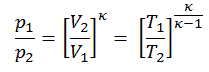
Then we will calculate the temperature, T2s, using p, V, T Relation for adiabatic process between (1 → 2).

p,V,T relation - isentropic process

In this equation the factor for helium is equal to =cp/cv=1.66. From the previous equation follows that the compressor outlet temperature, T2s, is:

isobaric process - example

From Ideal Gas Law we know, that the molar specific heat of a monatomic ideal gas is:

Cv = 3/2R = 12.5 J/mol K and Cp = Cv + R = 5/2R = 20.8 J/mol K

We transfer the specific heat capacities into units of J/kg K via:

cp = Cp . 1/M (molar weight of helium) = 20.8 x 4.10-3 = 5200 J/kg K

Using this temperature and the isentropic compressor efficiency we can calculate the heat added by the heat exchanger:

Qadd = cp(T3-T1) – (cp(T2s-T1)/ηK) = 5200.(1190 – 299) – 5200.(424-299)/0.87 = 4.633 MJ/kg – 0.747 MJ/kg = 3.886 MJ/kg

 
References:
Nuclear and Reactor Physics:
  1. J. R. Lamarsh, Introduction to Nuclear Reactor Theory, 2nd ed., Addison-Wesley, Reading, MA (1983).
  2. J. R. Lamarsh, A. J. Baratta, Introduction to Nuclear Engineering, 3d ed., Prentice-Hall, 2001, ISBN: 0-201-82498-1.
  3. W. M. Stacey, Nuclear Reactor Physics, John Wiley & Sons, 2001, ISBN: 0- 471-39127-1.
  4. Glasstone, Sesonske. Nuclear Reactor Engineering: Reactor Systems Engineering, Springer; 4th edition, 1994, ISBN: 978-0412985317
  5. W.S.C. Williams. Nuclear and Particle Physics. Clarendon Press; 1 edition, 1991, ISBN: 978-0198520467
  6. Kenneth S. Krane. Introductory Nuclear Physics, 3rd Edition, Wiley, 1987, ISBN: 978-0471805533
  7. G.R.Keepin. Physics of Nuclear Kinetics. Addison-Wesley Pub. Co; 1st edition, 1965
  8. Robert Reed Burn, Introduction to Nuclear Reactor Operation, 1988.
  9. U.S. Department of Energy, Nuclear Physics and Reactor Theory. DOE Fundamentals Handbook, Volume 1 and 2. January 1993.

Advanced Reactor Physics:

  1. K. O. Ott, W. A. Bezella, Introductory Nuclear Reactor Statics, American Nuclear Society, Revised edition (1989), 1989, ISBN: 0-894-48033-2.
  2. K. O. Ott, R. J. Neuhold, Introductory Nuclear Reactor Dynamics, American Nuclear Society, 1985, ISBN: 0-894-48029-4.
  3. D. L. Hetrick, Dynamics of Nuclear Reactors, American Nuclear Society, 1993, ISBN: 0-894-48453-2.
  4. E. E. Lewis, W. F. Miller, Computational Methods of Neutron Transport, American Nuclear Society, 1993, ISBN: 0-894-48452-4.

See also:

Thermodynamic Processes

We hope, this article, Isobaric Process, helps you. If so, give us a like in the sidebar. Main purpose of this website is to help the public to learn some interesting and important information about thermal engineering.
What is Isothermal Process and Adiabatic Process – Definition

An adiabatic process is not necessarily an isothermal process, nor is an isothermal process necessarily adiabatic. Characteristics of adiabatic and isothermal processes. Thermal Engineering

Isothermal Process

Characteristics of Isothermal Process
Isothermal process - main characteristics
Isothermal process – main characteristics
Boyle-Mariotte Law
Boyle-Mariotte Law. For a fixed mass of gas at constant temperature, the volume is inversely proportional to the pressure. Source: grc.nasa.gov NASA copyright policy states that “NASA material is not protected by copyright unless noted”.
[/su_accordion]
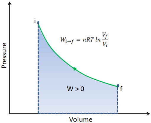
An isothermal process is a thermodynamic process, in which the temperature of the system remains constant (T = const). The heat transfer into or out of the system typically must happen at such a slow rate in order to continually adjust to the temperature of the reservoir through heat exchange. In each of these states the thermal equilibrium is maintained.

For an ideal gas and a polytropic process, the case n = 1 corresponds to an isothermal (constant-temperature) process. In contrast to adiabatic process , in which n = κ  and a system exchanges no heat with its surroundings (Q = 0; ∆T≠0), in an isothermal process there is no change in the internal energy (due to ∆T=0) and therefore ΔU = 0 (for ideal gases) and Q ≠ 0. An adiabatic process is not necessarily an isothermal process, nor is an isothermal process necessarily adiabatic.

In engineering, phase changes, such as evaporation or melting, are isothermal processes when, as is usually the case, they occur at constant pressure and temperature.

Isothermal Process and the First Law

The classical form of the first law of thermodynamics is the following equation:

dU = dQ – dW

In this equation dW is equal to dW = pdV and is known as the boundary work.

In isothermal process and the ideal gas, all heat added to the system will be used to do work:

Isothermal process (dU = 0):

dU = 0 = Q – W    →     W = Q      (for ideal gas)

The isothermal process can be expressed with the ideal gas law as:

pV = constant

or

p1V1 = p2V2

On a p-V diagram, the process occurs along a line (called an isotherm) that has the equation p = constant / V.

Adiabatic Process

Characteristics of Adiabatic Process
Main characteristics of adiabatic process
[/su_accordion]
An adiabatic process is a thermodynamic process, in which there is no heat transfer into or out of the system (Q = 0). The system can be considered to be perfectly insulated. In an adiabatic process, energy is transferred only as work. The assumption of no heat transfer is very important, since we can use the adiabatic approximation only in very rapid processes. In these rapid processes, there is not enough time for the transfer of energy as heat to take place to or from the system.

In real devices (such as turbines, pumps, and compressors) heat losses and losses in the combustion process occur, but these losses are usually low in comparison to overall energy flow and we can approximate some thermodynamic processes by the adiabatic process.

Adiabatic Process and the First Law

For a closed system, we can write the first law of thermodynamics in terms of enthalpy:

dH = dQ + Vdp

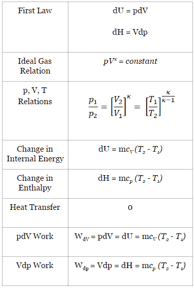
In this equation the term Vdp is a flow process work. This work,  Vdp, is used for open flow systems like a turbine or a pump in which there is a “dp”, i.e. change in pressure. As can be seen, this form of the law simplifies the description of energy transfer. In adiabatic process, the enthalpy change equals the flow process work done on or by the system:

Adiabatic process (dQ = 0):

dH = Vdp     →     W = H2 – H1     →     H2 – H1 = Cp (T2 – T1)    (for an ideal gas)

Adiabatic Expansion

P-V diagram - adiabatic process
Assume an adiabatic expansion of helium (3 → 4) in a gas turbine (Brayton cycle).

Free Expansion – Joule Expansion

These are adiabatic processes in which no transfer of heat occurs between the system and its environment and no work is done on or by the system. These types of adiabatic processes are called free expansion. It is an irreversible process in which a gas expands into an insulated evacuated chamber. It is also called Joule expansion. For an ideal gas, the temperature doesn’t change (this means that the process is also isothermal), however, real gases experience a temperature change during free expansion. In free expansion Q = W = 0, and the first law requires that:

dEint = 0

A free expansion can not be plotted on a P-V diagram, because the process is rapid, not quasistatic. The intermediate states are not equilibrium states, and hence the pressure is not clearly defined.

 
References:
Nuclear and Reactor Physics:
  1. J. R. Lamarsh, Introduction to Nuclear Reactor Theory, 2nd ed., Addison-Wesley, Reading, MA (1983).
  2. J. R. Lamarsh, A. J. Baratta, Introduction to Nuclear Engineering, 3d ed., Prentice-Hall, 2001, ISBN: 0-201-82498-1.
  3. W. M. Stacey, Nuclear Reactor Physics, John Wiley & Sons, 2001, ISBN: 0- 471-39127-1.
  4. Glasstone, Sesonske. Nuclear Reactor Engineering: Reactor Systems Engineering, Springer; 4th edition, 1994, ISBN: 978-0412985317
  5. W.S.C. Williams. Nuclear and Particle Physics. Clarendon Press; 1 edition, 1991, ISBN: 978-0198520467
  6. Kenneth S. Krane. Introductory Nuclear Physics, 3rd Edition, Wiley, 1987, ISBN: 978-0471805533
  7. G.R.Keepin. Physics of Nuclear Kinetics. Addison-Wesley Pub. Co; 1st edition, 1965
  8. Robert Reed Burn, Introduction to Nuclear Reactor Operation, 1988.
  9. U.S. Department of Energy, Nuclear Physics and Reactor Theory. DOE Fundamentals Handbook, Volume 1 and 2. January 1993.

Advanced Reactor Physics:

  1. K. O. Ott, W. A. Bezella, Introductory Nuclear Reactor Statics, American Nuclear Society, Revised edition (1989), 1989, ISBN: 0-894-48033-2.
  2. K. O. Ott, R. J. Neuhold, Introductory Nuclear Reactor Dynamics, American Nuclear Society, 1985, ISBN: 0-894-48029-4.
  3. D. L. Hetrick, Dynamics of Nuclear Reactors, American Nuclear Society, 1993, ISBN: 0-894-48453-2.
  4. E. E. Lewis, W. F. Miller, Computational Methods of Neutron Transport, American Nuclear Society, 1993, ISBN: 0-894-48452-4.

See also:

Thermodynamic Processes

We hope, this article, Isothermal Process and Adiabatic Process, helps you. If so, give us a like in the sidebar. Main purpose of this website is to help the public to learn some interesting and important information about thermal engineering.
What is Isobaric Process – Heat and Energy – Definition

Isobaric Process – Heat and Energy. In an isobaric process and the ideal gas, part of heat added to the system will be used to do work and part of heat added will increase the internal energy. Thermal Engineering

Isobaric Process – Heat and Energy

Isobaric Process – Heat and Energy

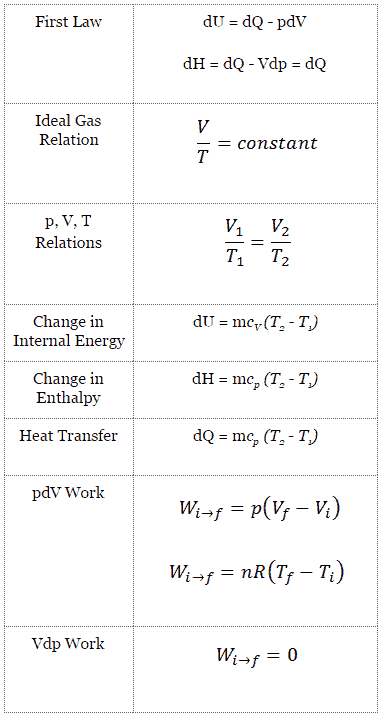
The classical form of the first law of thermodynamics is the following equation:

dU = dQ – dW

In this equation dW is equal to dW = pdV and is known as the boundary work.

In an isobaric process and the ideal gas, part of heat added to the system will be used to do work and part of heat added will increase the internal energy (increase the temperature).  Therefore it is convenient to use the enthalpy instead of the internal energy.Since H = U + pV, therefore dH = dU + pdV + Vdp and we substitute dU = dH – pdV – Vdp into the classical form of the law:

dH – pdV – Vdp = dQ – pdV

We obtain the law in terms of enthalpy:

dH = dQ + Vdp

or

dH = TdS + Vdp

In this equation the term Vdp is a flow process work. This work,  Vdp, is used for open flow systems like a turbine or a pump in which there is a “dp”, i.e. change in pressure. There are no changes in control volume. As can be seen, this form of the law simplifies the description of energy transfer. At constant pressure, the enthalpy change equals the energy transferred from the environment through heating:

Isobaric process (Vdp = 0):

dH = dQ     →     Q = H2 – H1

At constant entropy, i.e. in isentropic process, the enthalpy change equals the flow process work done on or by the system.

Isentropic process (dQ = 0):

dH = Vdp     →     W = H2 – H1

It is obvious, it will be very useful in analysis of both thermodynamic cycles used in power engineering, i.e. in Brayton cycle and Rankine cycle.

Isobaric process - main characteristics
Isobaric process – main characteristics
Charles's Law is one of the gas laws.
For a fixed mass of gas at constant pressure, the volume is directly proportional to the Kelvin temperature. Source: grc.nasa.gov NASA copyright policy states that “NASA material is not protected by copyright unless noted”.
 
Example: Frictionless Piston – Heat – Enthalpy
Enthalpy - Example - A frictionless piston
Calculate the final temperature, if 3000 kJ of heat is added.

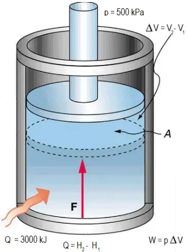
A frictionless piston is used to provide a constant pressure of 500 kPa in a cylinder containing steam (superheated steam) of a volume of 2 m3  at 500 K. Calculate the final temperature, if 3000 kJ of heat is added.

Solution:

Using steam tables we know, that the specific enthalpy of such steam (500 kPa; 500 K) is about 2912 kJ/kg. Since at this condition the steam has density of 2.2 kg/m3, then we know there is about 4.4 kg of steam in the piston at enthalpy of 2912 kJ/kg x 4.4 kg = 12812 kJ.

When we use simply Q = H2 − H1, then the resulting enthalpy of steam will be:

H2 = H1 + Q = 15812 kJ

From steam tables, such superheated steam (15812/4.4 = 3593 kJ/kg) will have a temperature of 828 K (555°C). Since at this enthalpy the steam have density of 1.31 kg/m3, it is obvious that it has expanded by about 2.2/1.31 = 1.67 (+67%). Therefore the resulting volume is 2 m3 x 1.67 = 3.34 m3 and ∆V = 3.34 m3 – 2 m3 = 1.34 m3.

The p∆V part of enthalpy, i.e. the work done is:

W = p∆V = 500 000 Pa x 1.34 m3 = 670 kJ

 
References:
Nuclear and Reactor Physics:
  1. J. R. Lamarsh, Introduction to Nuclear Reactor Theory, 2nd ed., Addison-Wesley, Reading, MA (1983).
  2. J. R. Lamarsh, A. J. Baratta, Introduction to Nuclear Engineering, 3d ed., Prentice-Hall, 2001, ISBN: 0-201-82498-1.
  3. W. M. Stacey, Nuclear Reactor Physics, John Wiley & Sons, 2001, ISBN: 0- 471-39127-1.
  4. Glasstone, Sesonske. Nuclear Reactor Engineering: Reactor Systems Engineering, Springer; 4th edition, 1994, ISBN: 978-0412985317
  5. W.S.C. Williams. Nuclear and Particle Physics. Clarendon Press; 1 edition, 1991, ISBN: 978-0198520467
  6. Kenneth S. Krane. Introductory Nuclear Physics, 3rd Edition, Wiley, 1987, ISBN: 978-0471805533
  7. G.R.Keepin. Physics of Nuclear Kinetics. Addison-Wesley Pub. Co; 1st edition, 1965
  8. Robert Reed Burn, Introduction to Nuclear Reactor Operation, 1988.
  9. U.S. Department of Energy, Nuclear Physics and Reactor Theory. DOE Fundamentals Handbook, Volume 1 and 2. January 1993.

Advanced Reactor Physics:

  1. K. O. Ott, W. A. Bezella, Introductory Nuclear Reactor Statics, American Nuclear Society, Revised edition (1989), 1989, ISBN: 0-894-48033-2.
  2. K. O. Ott, R. J. Neuhold, Introductory Nuclear Reactor Dynamics, American Nuclear Society, 1985, ISBN: 0-894-48029-4.
  3. D. L. Hetrick, Dynamics of Nuclear Reactors, American Nuclear Society, 1993, ISBN: 0-894-48453-2.
  4. E. E. Lewis, W. F. Miller, Computational Methods of Neutron Transport, American Nuclear Society, 1993, ISBN: 0-894-48452-4.

See also:

Isobaric Process

We hope, this article, Isobaric Process – Heat and Energy, helps you. If so, give us a like in the sidebar. Main purpose of this website is to help the public to learn some interesting and important information about thermal engineering.
What is Isobaric Process – Ideal Gas Equation – Definition

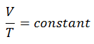
Isobaric Process – Ideal Gas Equation. The isobaric process can be expressed with the ideal gas law as: V/T = constant. Thermal Engineering

Isobaric Process – Ideal Gas Equation

See also: What is an Ideal Gas

isobaric process - work - pV diagram
On a p-V diagram, the process occurs along a horizontal line (called an isobar) that has the equation p = constant.

Let assume an isobaric heat addition in an ideal gas. In an ideal gas, molecules have no volume and do not interact. According to the ideal gas law, pressure varies linearly with temperature and quantity, and inversely with volume.

pV = nRT

where:

  • p is the absolute pressure of the gas
  • n is the amount of substance
  • T is the absolute temperature
  • V is the volume
  • R  is the ideal, or universal, gas constant, equal to the product of the Boltzmann constant and the Avogadro constant,

In this equation the symbol R is a constant called the universal gas constant that has the same value for all gases—namely, R =  8.31 J/mol K.

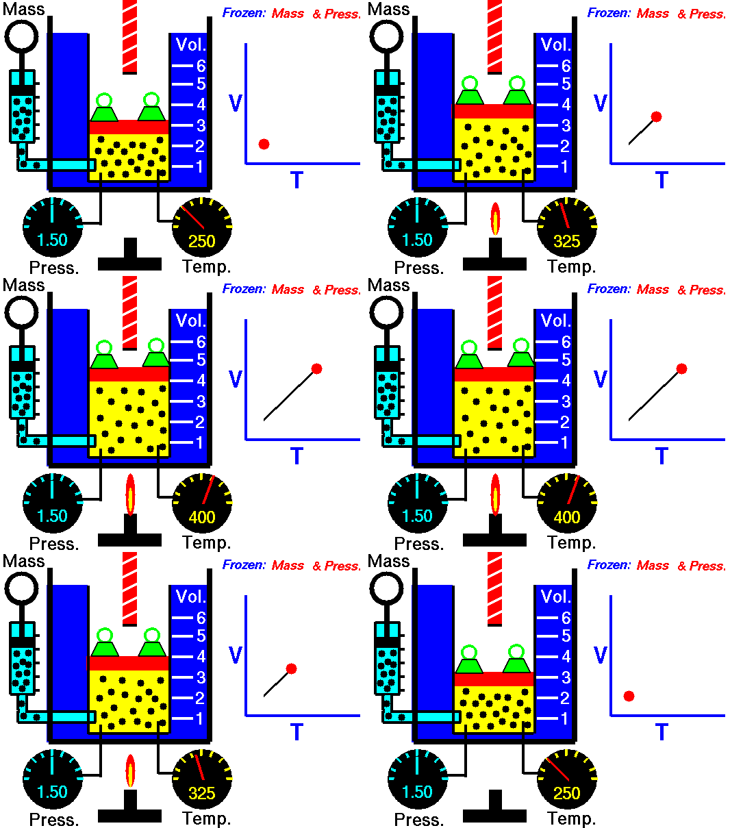
The isobaric process can be expressed with the ideal gas law as:

isobaric process - equation - 2

or

isobaric process - equation - 3

On a p-V diagram, the process occurs along a horizontal line (called an isobar) that has the equation p = constant.

Pressure-volume work by the closed system is defined as:

pV work - isobaric process

Assuming that the quantity of ideal gas remains constant and applying the ideal gas law, this becomes

isobaric process - work equation

According to the ideal gas model, the internal energy can be calculated by:

∆U = m cv ∆T

where the property cv (J/mol K) is referred to as specific heat (or heat capacity) at a constant volume because under certain special conditions (constant volume) it relates the temperature change of a system to the amount of energy added by heat transfer.

Adding these equations together, we obtain the equation for heat:

Q =  m cv ∆T + m R ∆T = m (cv +R)∆T = m cp ∆T

where the property cp (J/mol K) is referred to as specific heat (or heat capacity) at a constant pressure.

See also: Specific Heat at Constant Volume and Constant Pressure

See also: Mayer’s formula

Isobaric process - main characteristics
Isobaric process – main characteristics
Charles's Law is one of the gas laws.
For a fixed mass of gas at constant pressure, the volume is directly proportional to the Kelvin temperature. Source: grc.nasa.gov NASA copyright policy states that “NASA material is not protected by copyright unless noted”.

Charles’s Law

Charles’s Law is one of the gas laws. At the end of the 18th century, a French inventor and scientist Jacques Alexandre César Charles studied the relationship between the volume and the temperature of a gas at constant pressure. The results of certain experiments with gases at relatively low pressure led Jacques Alexandre César Charles to formulate a well-known law. It states that:

For a fixed mass of gas at constant pressure, the volume is directly proportional to the Kelvin temperature.

That means that, for example, if you double the temperature, you will double the volume. If you halve the temperature, you will halve the volume.

You can express this mathematically as:

V = constant . T

Yes, it seems to be identical as isobaric process of ideal gas. These results are fully consistent with ideal gas law, which determinates, that the constant is equal to nR/p. If you rearrange the pV = nRT equation by dividing both sides by p, you will obtain:

V = nR/p  .  T

where nR/p is constant and:

  • p is the absolute pressure of the gas
  • n is the amount of substance
  • T is the absolute temperature
  • V is the volume
  • R  is the ideal, or universal, gas constant, equal to the product of the Boltzmann constant and the Avogadro constant,

In this equation the symbol R is a constant called the universal gas constant that has the same value for all gases—namely, R =  8.31 J/mol K.

 
References:
Nuclear and Reactor Physics:
  1. J. R. Lamarsh, Introduction to Nuclear Reactor Theory, 2nd ed., Addison-Wesley, Reading, MA (1983).
  2. J. R. Lamarsh, A. J. Baratta, Introduction to Nuclear Engineering, 3d ed., Prentice-Hall, 2001, ISBN: 0-201-82498-1.
  3. W. M. Stacey, Nuclear Reactor Physics, John Wiley & Sons, 2001, ISBN: 0- 471-39127-1.
  4. Glasstone, Sesonske. Nuclear Reactor Engineering: Reactor Systems Engineering, Springer; 4th edition, 1994, ISBN: 978-0412985317
  5. W.S.C. Williams. Nuclear and Particle Physics. Clarendon Press; 1 edition, 1991, ISBN: 978-0198520467
  6. Kenneth S. Krane. Introductory Nuclear Physics, 3rd Edition, Wiley, 1987, ISBN: 978-0471805533
  7. G.R.Keepin. Physics of Nuclear Kinetics. Addison-Wesley Pub. Co; 1st edition, 1965
  8. Robert Reed Burn, Introduction to Nuclear Reactor Operation, 1988.
  9. U.S. Department of Energy, Nuclear Physics and Reactor Theory. DOE Fundamentals Handbook, Volume 1 and 2. January 1993.

Advanced Reactor Physics:

  1. K. O. Ott, W. A. Bezella, Introductory Nuclear Reactor Statics, American Nuclear Society, Revised edition (1989), 1989, ISBN: 0-894-48033-2.
  2. K. O. Ott, R. J. Neuhold, Introductory Nuclear Reactor Dynamics, American Nuclear Society, 1985, ISBN: 0-894-48029-4.
  3. D. L. Hetrick, Dynamics of Nuclear Reactors, American Nuclear Society, 1993, ISBN: 0-894-48453-2.
  4. E. E. Lewis, W. F. Miller, Computational Methods of Neutron Transport, American Nuclear Society, 1993, ISBN: 0-894-48452-4.

See also:

Isobaric Process

We hope, this article, Isobaric Process – Ideal Gas Equation, helps you. If so, give us a like in the sidebar. Main purpose of this website is to help the public to learn some interesting and important information about thermal engineering.
What is Example of Isobaric Process – Isobaric Heat Addition – Definition

Example of Isobaric Process – Isobaric Heat Addition. Let assume an isobaric heat addition in an ideal gas. Calculate the heat added by the heat exchanger. Thermal Engineering

Example of Isobaric Process – Isobaric Heat Addition

first law - example - brayton cycle
Ideal Brayton cycle consist of four thermodynamic processes. Two isentropic processes and two isobaric processes.

Let assume the ideal Brayton cycle that describes the workings of a constant pressure heat engine. Modern gas turbine engines and airbreathing jet engines also follow the Brayton cycle.

Ideal Brayton cycle consist of four thermodynamic processes. Two isentropic processes and two isobaric processes.

  1. isentropic compression – ambient air is drawn into the compressor, where it is pressurized (1 → 2). The work required for the compressor is given by WC = H2 – H1.
  2. isobaric heat addition – the compressed air then runs through a combustion chamber, where fuel is burned and air or another medium is heated (2 → 3). It is a constant-pressure process, since the chamber is open to flow in and out. The net heat added is given by Qadd = H3 – H2
  3. isentropic expansion – the heated, pressurized air then expands on turbine, gives up its energy. The work done by turbine is given by WT = H4 – H3
  4. isobaric heat rejection – the residual heat must be rejected in order to close the cycle. The net heat rejected is given by Qre = H4 – H1

Assume an isobaric heat addition (2 → 3) in a heat exchanger. In typical gas turbines the high-pressure stage receives gas (point 3 at the figure; p3 = 6.7 MPa; T3 = 1190 K (917°C)) from a heat exchanger. Moreover we know, that the compressor receives gas (point 1 at the figure; p1 = 2.78 MPa; T1 = 299 K (26°C)) and we know that the isentropic efficiency of the compressor is ηK = 0.87 (87%).

Calculate the heat added by the heat exchanger (between 2 → 3).

Solution:

From the first law of thermodynamics, the net heat added is given by Qadd = H3 – H2 or Qadd = Cp.(T3-T2s), but in this case we do not know the temperature (T2s) at the outlet of the compressor. We will solve this problem in intensive variables. We have to rewrite the previous equation (to include ηK) using the term (+h1 – h1) to:

Qadd = h3 – h2 = h3 – h1 – (h2s – h1)/ηK  

Qadd = cp(T3-T1) – (cp(T2s-T1)/ηK)

Then we will calculate the temperature, T2s, using p, V, T Relation for adiabatic process between (1 → 2).

p,V,T relation - isentropic process

In this equation the factor for helium is equal to =cp/cv=1.66. From the previous equation follows that the compressor outlet temperature, T2s, is:

isobaric process - example

From Ideal Gas Law we know, that the molar specific heat of a monatomic ideal gas is:

Cv = 3/2R = 12.5 J/mol K and Cp = Cv + R = 5/2R = 20.8 J/mol K

We transfer the specific heat capacities into units of J/kg K via:

cp = Cp . 1/M (molar weight of helium) = 20.8 x 4.10-3 = 5200 J/kg K

Using this temperature and the isentropic compressor efficiency we can calculate the heat added by the heat exchanger:

Qadd = cp(T3-T1) – (cp(T2s-T1)/ηK) = 5200.(1190 – 299) – 5200.(424-299)/0.87 = 4.633 MJ/kg – 0.747 MJ/kg = 3.886 MJ/kg

Isobaric process - main characteristics
Isobaric process – main characteristics
Charles's Law is one of the gas laws.
For a fixed mass of gas at constant pressure, the volume is directly proportional to the Kelvin temperature. Source: grc.nasa.gov NASA copyright policy states that “NASA material is not protected by copyright unless noted”.
 
Example: Frictionless Piston – Heat – Enthalpy
Enthalpy - Example - A frictionless piston
Calculate the final temperature, if 3000 kJ of heat is added.

A frictionless piston is used to provide a constant pressure of 500 kPa in a cylinder containing steam (superheated steam) of a volume of 2 m3  at 500 K. Calculate the final temperature, if 3000 kJ of heat is added.

Solution:

Using steam tables we know, that the specific enthalpy of such steam (500 kPa; 500 K) is about 2912 kJ/kg. Since at this condition the steam has density of 2.2 kg/m3, then we know there is about 4.4 kg of steam in the piston at enthalpy of 2912 kJ/kg x 4.4 kg = 12812 kJ.

When we use simply Q = H2 − H1, then the resulting enthalpy of steam will be:

H2 = H1 + Q = 15812 kJ

From steam tables, such superheated steam (15812/4.4 = 3593 kJ/kg) will have a temperature of 828 K (555°C). Since at this enthalpy the steam have density of 1.31 kg/m3, it is obvious that it has expanded by about 2.2/1.31 = 1.67 (+67%). Therefore the resulting volume is 2 m3 x 1.67 = 3.34 m3 and ∆V = 3.34 m3 – 2 m3 = 1.34 m3.

The p∆V part of enthalpy, i.e. the work done is:

W = p∆V = 500 000 Pa x 1.34 m3 = 670 kJ

 
References:
Nuclear and Reactor Physics:
  1. J. R. Lamarsh, Introduction to Nuclear Reactor Theory, 2nd ed., Addison-Wesley, Reading, MA (1983).
  2. J. R. Lamarsh, A. J. Baratta, Introduction to Nuclear Engineering, 3d ed., Prentice-Hall, 2001, ISBN: 0-201-82498-1.
  3. W. M. Stacey, Nuclear Reactor Physics, John Wiley & Sons, 2001, ISBN: 0- 471-39127-1.
  4. Glasstone, Sesonske. Nuclear Reactor Engineering: Reactor Systems Engineering, Springer; 4th edition, 1994, ISBN: 978-0412985317
  5. W.S.C. Williams. Nuclear and Particle Physics. Clarendon Press; 1 edition, 1991, ISBN: 978-0198520467
  6. Kenneth S. Krane. Introductory Nuclear Physics, 3rd Edition, Wiley, 1987, ISBN: 978-0471805533
  7. G.R.Keepin. Physics of Nuclear Kinetics. Addison-Wesley Pub. Co; 1st edition, 1965
  8. Robert Reed Burn, Introduction to Nuclear Reactor Operation, 1988.
  9. U.S. Department of Energy, Nuclear Physics and Reactor Theory. DOE Fundamentals Handbook, Volume 1 and 2. January 1993.

Advanced Reactor Physics:

  1. K. O. Ott, W. A. Bezella, Introductory Nuclear Reactor Statics, American Nuclear Society, Revised edition (1989), 1989, ISBN: 0-894-48033-2.
  2. K. O. Ott, R. J. Neuhold, Introductory Nuclear Reactor Dynamics, American Nuclear Society, 1985, ISBN: 0-894-48029-4.
  3. D. L. Hetrick, Dynamics of Nuclear Reactors, American Nuclear Society, 1993, ISBN: 0-894-48453-2.
  4. E. E. Lewis, W. F. Miller, Computational Methods of Neutron Transport, American Nuclear Society, 1993, ISBN: 0-894-48452-4.

See also:

Isobaric Process

We hope, this article, Example of Isobaric Process – Isobaric Heat Addition, helps you. If so, give us a like in the sidebar. Main purpose of this website is to help the public to learn some interesting and important information about thermal engineering.
What is Isobaric Curve – Isobar – pV Diagram – Definition

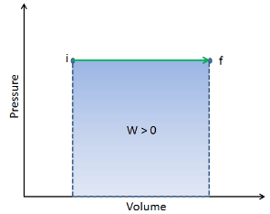
Isobaric Curve – Isobar – pV Diagram. On a p-V diagram, the process occurs along a horizontal line (called an isobar) that has the equation p = constant

Isobaric Process

An isobaric process is a thermodynamic process, in which the pressure of the system remains constant (p = const). The heat transfer into or out of the system does work, but also changes the internal energy of the system.

On a p-V diagram, the process occurs along a horizontal line (called an isobar) that has the equation p = constant.

isobaric process - work - pV diagram
On a p-V diagram, the process occurs along a horizontal line (called an isobar) that has the equation p = constant.
Isobaric process - main characteristics
Isobaric process – main characteristics
Charles's Law is one of the gas laws.
For a fixed mass of gas at constant pressure, the volume is directly proportional to the Kelvin temperature. Source: grc.nasa.gov NASA copyright policy states that “NASA material is not protected by copyright unless noted”.
 
References:
Nuclear and Reactor Physics:
  1. J. R. Lamarsh, Introduction to Nuclear Reactor Theory, 2nd ed., Addison-Wesley, Reading, MA (1983).
  2. J. R. Lamarsh, A. J. Baratta, Introduction to Nuclear Engineering, 3d ed., Prentice-Hall, 2001, ISBN: 0-201-82498-1.
  3. W. M. Stacey, Nuclear Reactor Physics, John Wiley & Sons, 2001, ISBN: 0- 471-39127-1.
  4. Glasstone, Sesonske. Nuclear Reactor Engineering: Reactor Systems Engineering, Springer; 4th edition, 1994, ISBN: 978-0412985317
  5. W.S.C. Williams. Nuclear and Particle Physics. Clarendon Press; 1 edition, 1991, ISBN: 978-0198520467
  6. Kenneth S. Krane. Introductory Nuclear Physics, 3rd Edition, Wiley, 1987, ISBN: 978-0471805533
  7. G.R.Keepin. Physics of Nuclear Kinetics. Addison-Wesley Pub. Co; 1st edition, 1965
  8. Robert Reed Burn, Introduction to Nuclear Reactor Operation, 1988.
  9. U.S. Department of Energy, Nuclear Physics and Reactor Theory. DOE Fundamentals Handbook, Volume 1 and 2. January 1993.

Advanced Reactor Physics:

  1. K. O. Ott, W. A. Bezella, Introductory Nuclear Reactor Statics, American Nuclear Society, Revised edition (1989), 1989, ISBN: 0-894-48033-2.
  2. K. O. Ott, R. J. Neuhold, Introductory Nuclear Reactor Dynamics, American Nuclear Society, 1985, ISBN: 0-894-48029-4.
  3. D. L. Hetrick, Dynamics of Nuclear Reactors, American Nuclear Society, 1993, ISBN: 0-894-48453-2.
  4. E. E. Lewis, W. F. Miller, Computational Methods of Neutron Transport, American Nuclear Society, 1993, ISBN: 0-894-48452-4.

See also:

Thermodynamic Processes

We hope, this article, Isobaric Curve – Isobar – pV Diagram, helps you. If so, give us a like in the sidebar. Main purpose of this website is to help the public to learn some interesting and important information about thermal engineering.
What is Isochoric Process – Isometric Process – Definition

Isochoric Process – Isometric Process. An isochoric process is a thermodynamic process, in which the volume of the closed system remains constant (V = const). Thermal Engineering

Isochoric Process – Isometric Process

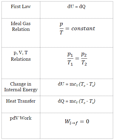
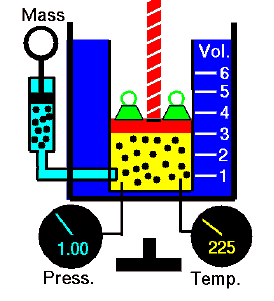
An isochoric process is a thermodynamic process, in which the volume of the closed system remains constant (V = const). It describes the behavior of gas inside the container, that cannot be deformed. Since the volume remains constant, the heat transfer into or out of the system does not the p∆V work, but only changes the internal energy (the temperature) of the system.

For an ideal gas and a polytropic process, the case n ➝ ∞  corresponds to an isochoric (constant-volume) process. In contrast to adiabatic process , in which n =  and a system exchanges no heat with its surroundings (Q = 0; W≠0), in an isochoric process there is a change in the internal energy (due to ∆T≠0) and therefore ΔU ≠ 0 (for ideal gases) and (Q ≠ 0; W=0).

In engineering of internal combustion engines, isochoric processes are very important for their thermodynamic cycles (Otto and Diesel cycle), therefore the study of this process is crucial for automotive engineering.

Isochoric Process and the First Law

The classical form of the first law of thermodynamics is the following equation:

dU = dQ – dW

In this equation dW is equal to dW = pdV and is known as the boundary work. Then:

dU = dQ  – pdV

In isochoric process and the ideal gas, all of heat added to the system will be used to increase the internal energy.

Isochoric process (pdV = 0):

dU = dQ    (for ideal gas)

Isochoric process - main characteristics
Isochoric process – main characteristics
Guy-Lussac's Law
For a fixed mass of gas at constant volume, the pressure is directly proportional to the Kelvin temperature.

Isochoric Process – Ideal Gas Equation

See also: What is an Ideal Gas

isochoric process - pV DiagramLet assume an isochoric heat addition in an ideal gas. In an ideal gas, molecules have no volume and do not interact. According to the ideal gas law, pressure varies linearly with temperature and quantity, and inversely with volume.

pV = nRT

where:

  • p is the absolute pressure of the gas
  • n is the amount of substance
  • T is the absolute temperature
  • V is the volume
  • R  is the ideal, or universal, gas constant, equal to the product of the Boltzmann constant and the Avogadro constant,

In this equation the symbol R is a constant called the universal gas constant that has the same value for all gases—namely, R =  8.31 J/mol K.

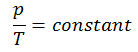
The isochoric process can be expressed with the ideal gas law as:

isochoric process - equation 1

or

isochoric process - equation 2

On a p-V diagram, the process occurs along a horizontal line that has the equation V = constant.

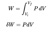
Pressure-volume work by the closed system is defined as:

pV work - isobaric process

Since the process is isochoric, dV = 0, the pressure-volume work is equal to zero. According to the ideal gas model, the internal energy can be calculated by:

∆U = m cv ∆T

where the property cv (J/mol K) is referred to as specific heat (or heat capacity) at a constant volume because under certain special conditions (constant volume) it relates the temperature change of a system to the amount of energy added by heat transfer.

Since there is no work done by or on the system, the first law of thermodynamics dictates ∆U = ∆Q. Therefore:

Q =  m cv ∆T

See also: Specific Heat at Constant Volume and Constant Pressure

See also: Mayer’s formula

Guy-Lussac’s Law

Guy-Lussac’s Law or the Pressure Law, one of the gas laws, states that:

For a fixed mass of gas at constant volume, the pressure is directly proportional to the Kelvin temperature.

That means that, for example, if you double the temperature, you will double the pressure. If you halve the temperature, you will halve the pressure.

You can express this mathematically as:

p = constant . T

Yes, it seems to be identical as isochoric process of ideal gas. These results are fully consistent with ideal gas law, which determinates, that the constant is equal to nR/V. If you rearrange the pV = nRT equation by dividing both sides by V, you will obtain:

p = nR/V  .  T

where nR/V is constant and:

  • p is the absolute pressure of the gas
  • n is the amount of substance
  • T is the absolute temperature
  • V is the volume
  • R  is the ideal, or universal, gas constant, equal to the product of the Boltzmann constant and the Avogadro constant

Example of Isochoric Process – Isochoric Heat Addition

Otto Cycle - PV DiagramLet assume the Otto Cycle, which is the one of most common thermodynamic cycles that can be found in automobile engines. This cycle assumes that the heat addition occurs instantaneously (between 2 → 3) while the piston is at top dead center. This process is considered to be isochoric.

Processes 2 → 3 and 4 → 1 are isochoric processes, in which the heat is transferred into the system between 2 → 3 and out of the system between 4 → 1. During these processes no work is done on the system or extracted from the system. The isochoric process 2 → 3 is intended to represent the ignition of the fuel–air mixture and the subsequent rapid burning.

 
References:
Nuclear and Reactor Physics:
  1. J. R. Lamarsh, Introduction to Nuclear Reactor Theory, 2nd ed., Addison-Wesley, Reading, MA (1983).
  2. J. R. Lamarsh, A. J. Baratta, Introduction to Nuclear Engineering, 3d ed., Prentice-Hall, 2001, ISBN: 0-201-82498-1.
  3. W. M. Stacey, Nuclear Reactor Physics, John Wiley & Sons, 2001, ISBN: 0- 471-39127-1.
  4. Glasstone, Sesonske. Nuclear Reactor Engineering: Reactor Systems Engineering, Springer; 4th edition, 1994, ISBN: 978-0412985317
  5. W.S.C. Williams. Nuclear and Particle Physics. Clarendon Press; 1 edition, 1991, ISBN: 978-0198520467
  6. Kenneth S. Krane. Introductory Nuclear Physics, 3rd Edition, Wiley, 1987, ISBN: 978-0471805533
  7. G.R.Keepin. Physics of Nuclear Kinetics. Addison-Wesley Pub. Co; 1st edition, 1965
  8. Robert Reed Burn, Introduction to Nuclear Reactor Operation, 1988.
  9. U.S. Department of Energy, Nuclear Physics and Reactor Theory. DOE Fundamentals Handbook, Volume 1 and 2. January 1993.

Advanced Reactor Physics:

  1. K. O. Ott, W. A. Bezella, Introductory Nuclear Reactor Statics, American Nuclear Society, Revised edition (1989), 1989, ISBN: 0-894-48033-2.
  2. K. O. Ott, R. J. Neuhold, Introductory Nuclear Reactor Dynamics, American Nuclear Society, 1985, ISBN: 0-894-48029-4.
  3. D. L. Hetrick, Dynamics of Nuclear Reactors, American Nuclear Society, 1993, ISBN: 0-894-48453-2.
  4. E. E. Lewis, W. F. Miller, Computational Methods of Neutron Transport, American Nuclear Society, 1993, ISBN: 0-894-48452-4.

See also:

Thermodynamic Processes

We hope, this article, Isochoric Process – Isometric Process, helps you. If so, give us a like in the sidebar. Main purpose of this website is to help the public to learn some interesting and important information about thermal engineering.

What is Isochoric Process – Ideal Gas Equation – pV Diagram – Definition

For an ideal gas and a polytropic process, the case n ➝ ∞ corresponds to an isochoric (constant-volume) process. On a p-V diagram, the process occurs along a horizontal line that has the equation V = constant. Thermal Engineering

Isochoric Process – Ideal Gas Equation

An isochoric process is a thermodynamic process, in which the volume of the closed system remains constant (V = const). It describes the behavior of gas inside the container, that cannot be deformed. Since the volume remains constant, the heat transfer into or out of the system does not the p∆V work, but only changes the internal energy (the temperature) of the system. For an ideal gas and a polytropic process, the case n ➝ ∞  corresponds to an isochoric (constant-volume) process.

See also: What is an Ideal Gas

isochoric process - pV DiagramLet assume an isochoric heat addition in an ideal gas. In an ideal gas, molecules have no volume and do not interact. According to the ideal gas law, pressure varies linearly with temperature and quantity, and inversely with volume.

pV = nRT

where:

  • p is the absolute pressure of the gas
  • n is the amount of substance
  • T is the absolute temperature
  • V is the volume
  • R  is the ideal, or universal, gas constant, equal to the product of the Boltzmann constant and the Avogadro constant,

In this equation the symbol R is a constant called the universal gas constant that has the same value for all gases—namely, R =  8.31 J/mol K.

The isochoric process can be expressed with the ideal gas law as:

isochoric process - equation 1

or

isochoric process - equation 2

On a p-V diagram, the process occurs along a horizontal line that has the equation V = constant.

Pressure-volume work by the closed system is defined as:

pV work - isobaric process

Since the process is isochoric, dV = 0, the pressure-volume work is equal to zero. According to the ideal gas model, the internal energy can be calculated by:

∆U = m cv ∆T

where the property cv (J/mol K) is referred to as specific heat (or heat capacity) at a constant volume because under certain special conditions (constant volume) it relates the temperature change of a system to the amount of energy added by heat transfer.

Since there is no work done by or on the system, the first law of thermodynamics dictates ∆U = ∆Q. Therefore:

Q =  m cv ∆T

See also: Specific Heat at Constant Volume and Constant Pressure

See also: Mayer’s formula

Isochoric process - main characteristics
Isochoric process – main characteristics
Guy-Lussac's Law
For a fixed mass of gas at constant volume, the pressure is directly proportional to the Kelvin temperature.
 
References:
Nuclear and Reactor Physics:
  1. J. R. Lamarsh, Introduction to Nuclear Reactor Theory, 2nd ed., Addison-Wesley, Reading, MA (1983).
  2. J. R. Lamarsh, A. J. Baratta, Introduction to Nuclear Engineering, 3d ed., Prentice-Hall, 2001, ISBN: 0-201-82498-1.
  3. W. M. Stacey, Nuclear Reactor Physics, John Wiley & Sons, 2001, ISBN: 0- 471-39127-1.
  4. Glasstone, Sesonske. Nuclear Reactor Engineering: Reactor Systems Engineering, Springer; 4th edition, 1994, ISBN: 978-0412985317
  5. W.S.C. Williams. Nuclear and Particle Physics. Clarendon Press; 1 edition, 1991, ISBN: 978-0198520467
  6. Kenneth S. Krane. Introductory Nuclear Physics, 3rd Edition, Wiley, 1987, ISBN: 978-0471805533
  7. G.R.Keepin. Physics of Nuclear Kinetics. Addison-Wesley Pub. Co; 1st edition, 1965
  8. Robert Reed Burn, Introduction to Nuclear Reactor Operation, 1988.
  9. U.S. Department of Energy, Nuclear Physics and Reactor Theory. DOE Fundamentals Handbook, Volume 1 and 2. January 1993.

Advanced Reactor Physics:

  1. K. O. Ott, W. A. Bezella, Introductory Nuclear Reactor Statics, American Nuclear Society, Revised edition (1989), 1989, ISBN: 0-894-48033-2.
  2. K. O. Ott, R. J. Neuhold, Introductory Nuclear Reactor Dynamics, American Nuclear Society, 1985, ISBN: 0-894-48029-4.
  3. D. L. Hetrick, Dynamics of Nuclear Reactors, American Nuclear Society, 1993, ISBN: 0-894-48453-2.
  4. E. E. Lewis, W. F. Miller, Computational Methods of Neutron Transport, American Nuclear Society, 1993, ISBN: 0-894-48452-4.

See also:

Isochoric Process

We hope, this article, Isochoric Process – Ideal Gas Equation – pV Diagram, helps you. If so, give us a like in the sidebar. Main purpose of this website is to help the public to learn some interesting and important information about thermal engineering.