Assume an isothermal expansion of helium (i → f) in a frictionless piston (closed system). The gas expansion is propelled by absorption of heat energy Qadd. Thermal Engineering
Example of Isothermal Process
Isothermal process – pV diagram
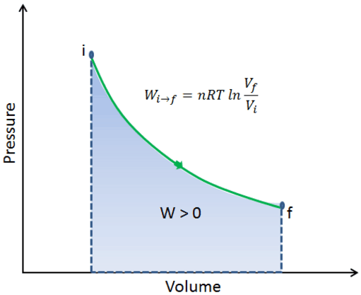
Assume an isothermal expansion of helium (i → f) in a frictionless piston (closed system). The gas expansion is propelled by absorption of heat energy Qadd. The gas expands from initial volume of 0.001 m3 and simultaneously the external load of the piston slowly and continuously decreases from 1 MPa to 0.5 MPa. Since helium behaves almost as an ideal gas, use the ideal gas lawto calculate final volume of the chamber and then calculate the work done by the system, when the temperature of the gas is equal to 400 K.
Solution:
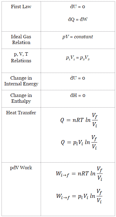
The final volume of the gas, Vf, can be calculated using p, V, T Relation for isothermal process:
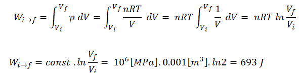
To calculate such processes, we would need to know how pressure varies with volume for the actual process by which the system changes from state i to state f. Since during this process the internal pressure was not constant, the p∆V work done by the piston must be calculated using the following integral:
By convention, a positive value for work indicates that work is done by the system on its surroundings. A negative value indicates that work is done on the system by its surroundings. The pΔV work is equal to the area under the process curve plotted on the pressure-volume diagram.
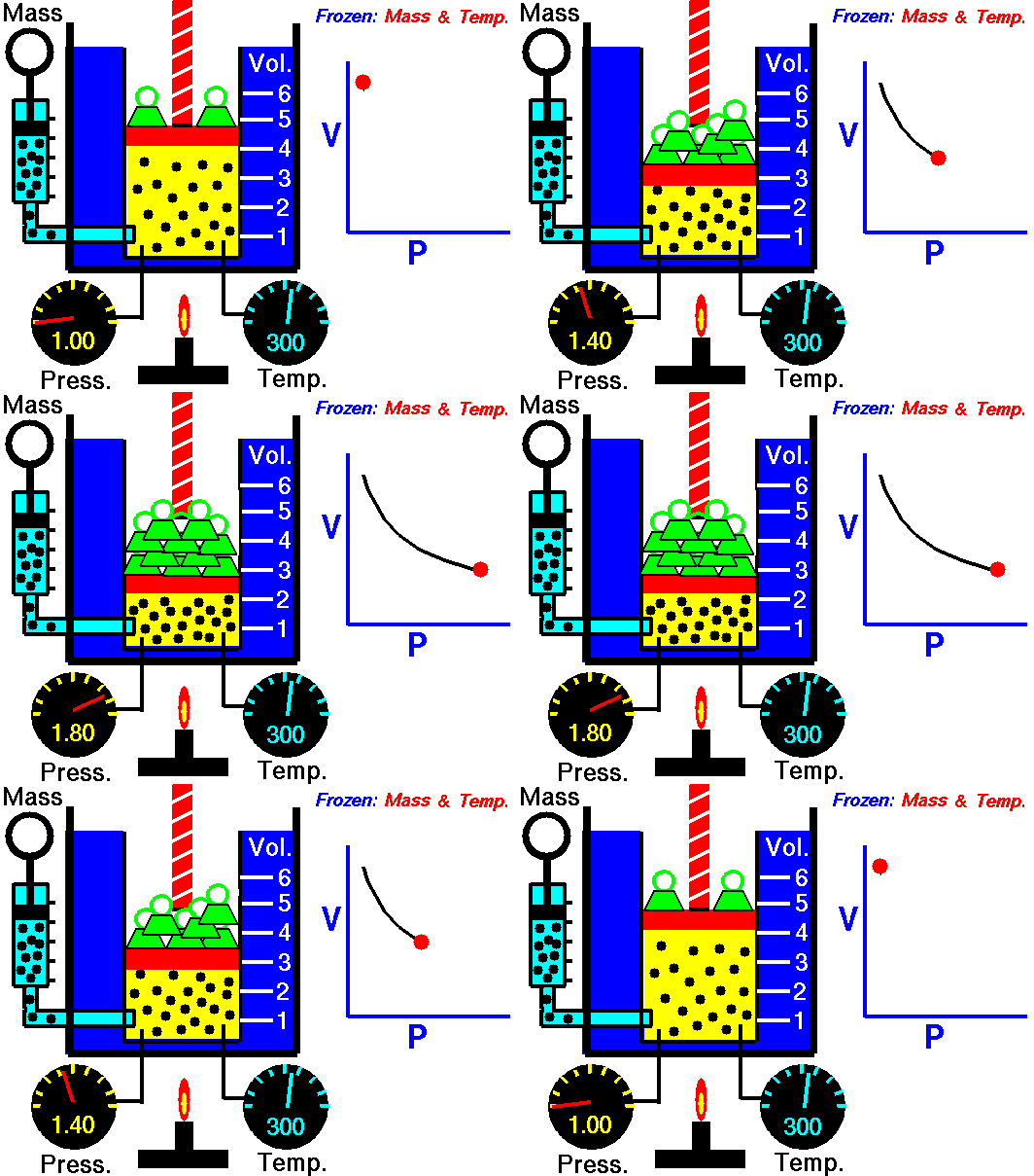
Isothermal process – main characteristicsBoyle-Mariotte Law. For a fixed mass of gas at constant temperature, the volume is inversely proportional to the pressure. Source: grc.nasa.gov NASA copyright policy states that “NASA material is not protected by copyright unless noted”.
References:
Nuclear and Reactor Physics:
J. R. Lamarsh, Introduction to Nuclear Reactor Theory, 2nd ed., Addison-Wesley, Reading, MA (1983).
J. R. Lamarsh, A. J. Baratta, Introduction to Nuclear Engineering, 3d ed., Prentice-Hall, 2001, ISBN: 0-201-82498-1.
W. M. Stacey, Nuclear Reactor Physics, John Wiley & Sons, 2001, ISBN: 0- 471-39127-1.
Robert Reed Burn, Introduction to Nuclear Reactor Operation, 1988.
U.S. Department of Energy, Nuclear Physics and Reactor Theory. DOE Fundamentals Handbook, Volume 1 and 2. January 1993.
Advanced Reactor Physics:
K. O. Ott, W. A. Bezella, Introductory Nuclear Reactor Statics, American Nuclear Society, Revised edition (1989), 1989, ISBN: 0-894-48033-2.
K. O. Ott, R. J. Neuhold, Introductory Nuclear Reactor Dynamics, American Nuclear Society, 1985, ISBN: 0-894-48029-4.
D. L. Hetrick, Dynamics of Nuclear Reactors, American Nuclear Society, 1993, ISBN: 0-894-48453-2.
E. E. Lewis, W. F. Miller, Computational Methods of Neutron Transport, American Nuclear Society, 1993, ISBN: 0-894-48452-4.
See also:
Isothermal Process
We hope, this article, Example of Isothermal Process, helps you. If so, give us a like in the sidebar. Main purpose of this website is to help the public to learn some interesting and important information about thermal engineering.
Carnot Efficiency or Efficiency of Carnot Heat Engine. is an idealized efficiency. It is valid only for reversible processes and depends only on temperature difference between reservoirs. Thermal Engineering
Carnot Efficiency – Efficiency of Carnot Heat Engine
In 1824, a French engineer and physicist, Nicolas Léonard Sadi Carnot advanced the study of the second law by forming a principle (also called Carnot’s rule) that specifies limits on the maximum efficiency any heat engine can obtain. In short, this principle states that the efficiency of a thermodynamic cycle depends solely on the difference between the hot and cold temperature reservoirs.
Carnot’s principle states:
No engine can be more efficient than a reversible engine (a Carnot heat engine) operating between the same high temperature and low temperature reservoirs.
The efficiencies of all reversible engines (Carnot heat engines) operating between the same constant temperature reservoirs are the same, regardless of the working substance employed or the operation details.
Carnot Efficiency
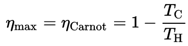
The formula for this maximum efficiency is:
where:
is the efficiency of Carnot cycle, i.e. it is the ratio = W/QH of the work done by the engine to the heat energy entering the system from the hot reservoir.
TC is the absolute temperature (Kelvins) of the cold reservoir,
TH is the absolute temperature (Kelvins) of the hot reservoir.
Example: Carnot efficiency for coal-fired power plant
In a modern coal-fired power plant, the temperature of high pressure steam (Thot) would be about 400°C (673K) and Tcold, the cooling tower water temperature, would be about 20°C (293K). For this type of power plant the maximum (ideal) efficiency will be:
= 1 – Tcold/Thot = 1 – 293/673 = 56%
It must be added, this is an idealized efficiency. The Carnot efficiency is valid for reversible processes. These processes cannot be achieved in real cycles of power plants. The Carnot efficiency dictates that higher efficiencies can be attained by increasing the temperature of the steam. This feature is valid also for real thermodynamic cycles. But this requires an increase in pressures inside boilers or steam generators. However, metallurgical considerations place an upper limits on such pressures. Sub-critical fossil fuel power plants, that are operated under critical pressure (i.e. lower than 22.1 MPa), can achieve 36–40% efficiency. Supercritical designs, that are operated at supercritical pressure (i.e. greater than 22.1 MPa), have efficiencies around 43%. Most efficient and also very complex coal-fired power plants that are operated at “ultra critical” pressures (i.e. around 30 MPa) and use multiple stage reheat reach about 48% efficiency.
As was discussed, an efficiency can range between 0 and 1. Each heat engine is somehow inefficient. This inefficiency can be attributed to three causes.
Irreversibility of Processes. There is an overall theoretical upper limit to the efficiency of conversion of heat to work in any heat engine. This upper limit is called the Carnot efficiency. According to the Carnot principle, no engine can be more efficient than a reversible engine (a Carnot heat engine) operating between the same high temperature and low temperature reservoirs. For example, when the hot reservoir have Thot of 400°C (673K) and Tcold of about 20°C (293K), the maximum (ideal) efficiency will be: = 1 – Tcold/Thot = 1 – 293/673 = 56%. But all real thermodynamic processes are somehow irreversible. They are not done infinitely slowly. Therefore, heat engines must have lower efficiencies than limits on their efficiency due to the inherent irreversibility of the heat engine cycle they use.
Presence of Friction and Heat Losses. In real thermodynamic systems or in real heat engines, a part of the overall cycle inefficiency is due to the losses by the individual components. In real devices (such as turbines, pumps, and compressors) a mechanical friction, heat losses and losses in the combustion process cause further efficiency losses.
Design Inefficiency. Finally, last and also important source of inefficiencies is from the compromises made by engineers when designing a heat engine (e.g. power plant). They must consider cost and other factors in the design and operation of the cycle. As an example consider a design of the condenser in the thermal power plants. Ideally the steam exhausted into the condenser would have no subcooling. But real condensers are designed to subcool the liquid by a few degrees of Celsius in order to avoid the suction cavitation in the condensate pumps. But, this subcooling increases the inefficiency of the cycle, because more energy is needed to reheat the water.
References:
Nuclear and Reactor Physics:
J. R. Lamarsh, Introduction to Nuclear Reactor Theory, 2nd ed., Addison-Wesley, Reading, MA (1983).
J. R. Lamarsh, A. J. Baratta, Introduction to Nuclear Engineering, 3d ed., Prentice-Hall, 2001, ISBN: 0-201-82498-1.
W. M. Stacey, Nuclear Reactor Physics, John Wiley & Sons, 2001, ISBN: 0- 471-39127-1.
Robert Reed Burn, Introduction to Nuclear Reactor Operation, 1988.
U.S. Department of Energy, Nuclear Physics and Reactor Theory. DOE Fundamentals Handbook, Volume 1 and 2. January 1993.
Advanced Reactor Physics:
K. O. Ott, W. A. Bezella, Introductory Nuclear Reactor Statics, American Nuclear Society, Revised edition (1989), 1989, ISBN: 0-894-48033-2.
K. O. Ott, R. J. Neuhold, Introductory Nuclear Reactor Dynamics, American Nuclear Society, 1985, ISBN: 0-894-48029-4.
D. L. Hetrick, Dynamics of Nuclear Reactors, American Nuclear Society, 1993, ISBN: 0-894-48453-2.
E. E. Lewis, W. F. Miller, Computational Methods of Neutron Transport, American Nuclear Society, 1993, ISBN: 0-894-48452-4.
See also:
Second Law
We hope, this article, Carnot Efficiency – Efficiency of Carnot Heat Engine, helps you. If so, give us a like in the sidebar. Main purpose of this website is to help the public to learn some interesting and important information about thermal engineering.
Carnot’s principle or Carnot’s rule specifies limits on the maximum efficiency any heat engine can obtain. No engine can be more efficient than a Carnot heat engine. Thermal Engineering
Carnot’s principle – Carnot’s rule
In 1824, a French engineer and physicist, Nicolas Léonard Sadi Carnot advanced the study of the second law by forming a principle (also called Carnot’s rule) that specifies limits on the maximum efficiency any heat engine can obtain. In short, Carnot’s principle states that the efficiency of a thermodynamic cycle depends solely on the difference between the hot and cold temperature reservoirs.
Carnot’s principle states:
No engine can be more efficient than a reversible engine (a Carnot heat engine) operating between the same high temperature and low temperature reservoirs.
The efficiencies of all reversible engines (Carnot heat engines) operating between the same constant temperature reservoirs are the same, regardless of the working substance employed or the operation details.
Carnot Efficiency
The formula for this maximum efficiency is:
where:
is the efficiency of Carnot cycle, i.e. it is the ratio = W/QH of the work done by the engine to the heat energy entering the system from the hot reservoir.
TC is the absolute temperature (Kelvins) of the cold reservoir,
TH is the absolute temperature (Kelvins) of the hot reservoir.
Example: Carnot efficiency for coal-fired power plant
In a modern coal-fired power plant, the temperature of high pressure steam (Thot) would be about 400°C (673K) and Tcold, the cooling tower water temperature, would be about 20°C (293K). For this type of power plant the maximum (ideal) efficiency will be:
= 1 – Tcold/Thot = 1 – 293/673 = 56%
It must be added, this is an idealized efficiency. The Carnot efficiency is valid for reversible processes. These processes cannot be achieved in real cycles of power plants. The Carnot efficiency dictates that higher efficiencies can be attained by increasing the temperature of the steam. This feature is valid also for real thermodynamic cycles. But this requires an increase in pressures inside boilers or steam generators. However, metallurgical considerations place an upper limits on such pressures. Sub-critical fossil fuel power plants, that are operated under critical pressure (i.e. lower than 22.1 MPa), can achieve 36–40% efficiency. Supercritical designs, that are operated at supercritical pressure (i.e. greater than 22.1 MPa), have efficiencies around 43%. Most efficient and also very complex coal-fired power plants that are operated at “ultra critical” pressures (i.e. around 30 MPa) and use multiple stage reheat reach about 48% efficiency.
Robert Reed Burn, Introduction to Nuclear Reactor Operation, 1988.
U.S. Department of Energy, Nuclear Physics and Reactor Theory. DOE Fundamentals Handbook, Volume 1 and 2. January 1993.
Advanced Reactor Physics:
K. O. Ott, W. A. Bezella, Introductory Nuclear Reactor Statics, American Nuclear Society, Revised edition (1989), 1989, ISBN: 0-894-48033-2.
K. O. Ott, R. J. Neuhold, Introductory Nuclear Reactor Dynamics, American Nuclear Society, 1985, ISBN: 0-894-48029-4.
D. L. Hetrick, Dynamics of Nuclear Reactors, American Nuclear Society, 1993, ISBN: 0-894-48453-2.
E. E. Lewis, W. F. Miller, Computational Methods of Neutron Transport, American Nuclear Society, 1993, ISBN: 0-894-48452-4.
See also:
Second Law
We hope, this article, Carnot’s principle – Carnot’s rule, helps you. If so, give us a like in the sidebar. Main purpose of this website is to help the public to learn some interesting and important information about thermal engineering.
In general, a heat engine is a device that converts chemical energy to heat or thermal energy and then to mechanical energy or to electrical energy. Many heat engines operate in a cyclic manner. Thermal Engineering
Heat Engines
Energy sources have always played a very important role in the development of human society. Energy is generally defined as the potential to do workor produce heat. Sometimes it is like the “currency” for performing work. One of the most wonderful properties of the universe is that energy can be transformed from one type to another and transferred from one object to another.
In general, it is easy to produce thermal energyby doing work, for example by any frictional process. But to get work from thermal energy is more difficult. It is closely associated with the concept of entropy. For example, electricity is particularly useful since it has verylow entropy (is highly ordered) and can be converted into other forms of energy very efficiently.
Sometimes, mechanical energy is directly available, for example wind power and hydro power. But most of our energy comes from the burning of fossil fuels (coal, oil, and gas) and from nuclear reactions. At present, fossil fuel is still the world’s predominant energy source. But the burning of fossil fuels generates only thermal energy, therefore these energy sources are so called “primary energy sources”, that must be converted to secondary energy source, so called energy carriers (electrical energy etc.). To convert thermal energy into another form of energy a heat engine must be used.
In general, a heat engine is a device that converts chemical energy to heat or thermal energy and then to mechanical energy or to electrical energy.
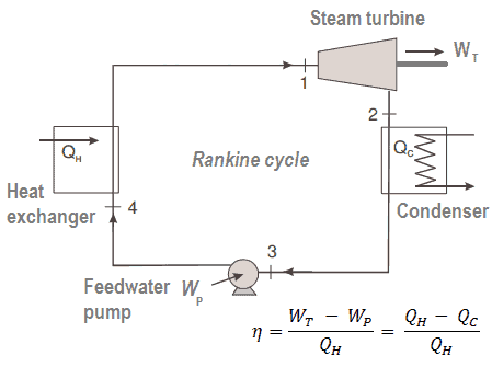
The Rankine cycle closely describes the processes in steam-operated heat engines commonly found in most of thermal power plants.
Many heat engines operate in a cyclic manner, adding energy in the form of heat in one part of the cycle and using that energy to do useful work in another part of the cycle.
For example, as is typical in all conventional thermal power plants the heat is used to generate steam which drives a steam turbine connected to a generator which produces electricity. Steam generators, steam turbines, condensers and feedwater pumps constitute a heat engine, that is subject to the efficiency limitations imposed by the second law of thermodynamics. In modern nuclear power plants the overall thermodynamic efficiency is about one-third (33%), so 3000 MWth of thermal power from the fission reaction is needed to generate 1000 MWe of electrical power.
Heat Engines and the Second Law
The second law of thermodynamics may be expressed in many specific ways. Each statement expresses the same law. Listed below are three that are often encountered.
Before these statements, we have to remind the work of a French engineer and physicist, Nicolas Léonard Sadi Carnot advanced the study of the second law by forming a principle (also called Carnot’s rule) that specifies limits on the maximum efficiency any heat engine can obtain.
Carnot's Principle
In 1824, a French engineer and physicist, Nicolas Léonard Sadi Carnot advanced the study of the second law by forming a principle (also called Carnot’s rule) that specifies limits on the maximum efficiency any heat engine can obtain. In short, this principle states that the efficiency of a thermodynamic cycle depends solely on the difference between the hot and cold temperature reservoirs.
Carnot’s principle states:
No engine can be more efficient than a reversible engine (a Carnot heat engine) operating between the same high temperature and low temperature reservoirs.
The efficiencies of all reversible engines (Carnot heat engines) operating between the same constant temperature reservoirs are the same, regardless of the working substance employed or the operation details.
Carnot Efficiency
The formula for this maximum efficiency is:
where:
is the efficiency of Carnot cycle, i.e. it is the ratio = W/QH of the work done by the engine to the heat energy entering the system from the hot reservoir.
TC is the absolute temperature (Kelvins) of the cold reservoir,
TH is the absolute temperature (Kelvins) of the hot reservoir.
Example: Carnot efficiency for coal-fired power plant
In a modern coal-fired power plant, the temperature of high pressure steam (Thot) would be about 400°C (673K) and Tcold, the cooling tower water temperature, would be about 20°C (293K). For this type of power plant the maximum (ideal) efficiency will be:
= 1 – Tcold/Thot = 1 – 293/673 = 56%
It must be added, this is an idealized efficiency. The Carnot efficiency is valid for reversible processes. These processes cannot be achieved in real cycles of power plants. The Carnot efficiency dictates that higher efficiencies can be attained by increasing the temperature of the steam. This feature is valid also for real thermodynamic cycles. But this requires an increase in pressures inside boilers or steam generators. However, metallurgical considerations place an upper limits on such pressures. Sub-critical fossil fuel power plants, that are operated under critical pressure (i.e. lower than 22.1 MPa), can achieve 36–40% efficiency. Supercritical designs, that are operated at supercritical pressure (i.e. greater than 22.1 MPa), have efficiencies around 43%. Most efficient and also very complex coal-fired power plants that are operated at “ultra critical” pressures (i.e. around 30 MPa) and use multiple stage reheat reach about 48% efficiency.
In general, heat engines are categorized according to a combustion location as:
External combustion engine. For example, steam engines are external combustion engines, where the working fluid is separate from the combustion products.
Internal combustion engine. Typical example of internal combustion engine is an engine used in automobile, in which the high temperature is achieved by burning the gasoline-air mixture in the cylinder itself.
The detailed categorization is based on a working fluid used in thermodynamic cycle:
Gas Cycles. In these cycles the working fluid is always a gas. The Otto cycle and the Diesel cycle (used is automobiles) are also typical examples of gas-only cycles. Modern gas turbine engines and airbreathing jet engines also based on the gas-only cycle, they follow the Brayton cycle.
Liquid Cycles. Liquid-only cycles are rather exotic. In these cycles the working fluid is always a liquid. The Malone liquid engine is an example of liquid-only cycle. The Malone liquid engine was a modification of the Stirling cycle, using water as the working fluid instead of gas
Cycles with Phase Changes. Steam engines are typical examples of external engines with phase change of working fluid.
Example of Heat Engine
The Rankine cycle closely describes the processes in steam-operated heat engines commonly found in most of thermal power plants.
Steam engines and refrigerators are typical examples of external engines with phase change of working fluid. Typical thermodynamic cycle used to analyze this process is called the Rankine cycle, which usually uses water as the working fluid.
The Rankine cycle closely describes the processes in steam-operated heat engines commonly found in most of thermal power plants. The heat sources used in these power plants are usually the combustion of fossil fuels such as coal, natural gas, or also the nuclear fission.
A nuclear power plant (nuclear power station) looks like a standard thermal power station with one exception. The heat source in the nuclear power plant is a nuclear reactor. As is typical in all conventional thermal power stations the heat is used to generate steam which drives a steam turbine connected to a generator which produces electricity.
Rankine Cycle – Thermodynamics as Energy Conversion Science
Typically most of nuclear power plants operates multi-stage condensing steam turbines. In these turbines the high-pressure stage receives steam (this steam is nearly saturated steam – x = 0.995 – point C at the figure; 6 MPa; 275.6°C) from a steam generator and exhaust it to moisture separator-reheater (point D). The steam must be reheated in order to avoid damages that could be caused to blades of steam turbine by low quality steam. The reheater heats the steam (point D) and then the steam is directed to the low-pressure stage of steam turbine, where expands (point E to F). The exhausted steam then condenses in the condenser and it is at a pressure well below atmospheric (absolute pressure of 0.008 MPa), and is in a partially condensed state (point F), typically of a quality near 90%.
In this case, steam generators, steam turbine, condensers and feedwater pumps constitute a heat engine, that is subject to the efficiency limitations imposed by the second law of thermodynamics. In ideal case (no friction, reversible processes, perfect design), this heat engine would have a Carnot efficiency of
= 1 – Tcold/Thot = 1 – 315/549 = 42.6%
where the temperature of the hot reservoir is 275.6°C (548.7K), the temperature of the cold reservoir is 41.5°C (314.7K). But the nuclear power plant is the real heat engine, in which thermodynamic processes are somehow irreversible. They are not done infinitely slowly. In real devices (such as turbines, pumps, and compressors) a mechanical friction and heat losses cause further efficiency losses.
Therefore nuclear power plants usually have efficiency about 33%. In modern nuclear power plants the overall thermodynamic efficiency is about one-third (33%), so 3000 MWth of thermal power from the fission reaction is needed to generate 1000 MWe of electrical power.
According to the Carnot’s principle higher efficiencies can be attained by increasing the temperature of the steam. But this requires an increase in pressures inside boilers or steam generators. However, metallurgical considerations place an upper limits on such pressures. From this point of view, supercritical water reactors are considered a promising advancement for nuclear power plants because of its high thermal efficiency (~45 % vs. ~33 % for current LWRs). SCWRs are operated at supercritical pressure (i.e. greater than 22.1 MPa).
Thermal Efficiency and the Second Law
An ideal heat engine is an imaginary engine in which energy extracted as heat from the high-temperature reservoir is converted completely to work. But according to the Kelvin-Planck statement, such an engine would violate the second law of thermodynamics, because there must be losses in the conversion process. The net heat added to the system must be higher than the net work done by the system.
Kelvin-Planck statement:
“It is impossible to construct a device which operates on a cycle and produces no other effect than the production of work and the transfer of heat from a single body”.
Thermal Efficiency Formula
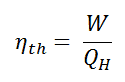
As a result of this statement, we define the thermal efficiency, ηth, of any heat engine as the ratio of the work it does, W, to the heat input at the high temperature, QH.
The thermal efficiency, ηth, represents the fraction of heat, QH, that is converted to work. It is a dimensionless performance measure of a heat engine that uses thermal energy, such as a steam turbine, an internal combustion engine, or a refrigerator. For a refrigeration or heat pumps, thermal efficiency indicates the extent to which the energy added by work is converted to net heat output. Since it is dimensionless number, we must always express W, QH, and QC in the same units.
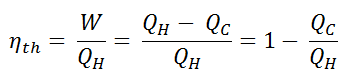
Since energy is conserved according to the first law of thermodynamicsand energy cannot be be converted to work completely, the heat input, QH, must equal the work done, W, plus the heat that must be dissipated as waste heat QC into the environment. Therefore we can rewrite the formula for thermal efficiency as:
To give the efficiency as a percent, we multiply the previous formula by 100. Note that, ηth could be 100% only if the waste heat QC will be zero.
In general, the efficiency of even the best heat engines is quite low. In short, it is very difficult to convert thermal energy to mechanical energy. The thermal efficiencies are usually below 50% and often far below. Be careful when you compare it with efficiencies of wind or hydro power (wind turbines are not heat engines), there is no energy conversion between the thermal and mechanical energy.
Causes of Inefficiency
As was discussed, an efficiency can range between 0 and 1. Each heat engine is somehow inefficient. This inefficiency can be attributed to three causes.
Irreversibility of Processes. There is an overall theoretical upper limit to the efficiency of conversion of heat to work in any heat engine. This upper limit is called the Carnot efficiency. According to the Carnot principle, no engine can be more efficient than a reversible engine (a Carnot heat engine) operating between the same high temperature and low temperature reservoirs. For example, when the hot reservoir have Thot of 400°C (673K) and Tcold of about 20°C (293K), the maximum (ideal) efficiency will be: = 1 – Tcold/Thot = 1 – 293/673 = 56%. But all real thermodynamic processes are somehow irreversible. They are not done infinitely slowly. Therefore, heat engines must have lower efficiencies than limits on their efficiency due to the inherent irreversibility of the heat engine cycle they use.
Presence of Friction and Heat Losses. In real thermodynamic systems or in real heat engines, a part of the overall cycle inefficiency is due to the losses by the individual components. In real devices (such as turbines, pumps, and compressors) a mechanical friction, heat losses and losses in the combustion process cause further efficiency losses.
Design Inefficiency. Finally, last and also important source of inefficiencies is from the compromises made by engineers when designing a heat engine (e.g. power plant). They must consider cost and other factors in the design and operation of the cycle. As an example consider a design of the condenser in the thermal power plants. Ideally the steam exhausted into the condenser would have no subcooling. But real condensers are designed to subcool the liquid by a few degrees of Celsius in order to avoid the suction cavitation in the condensate pumps. But, this subcooling increases the inefficiency of the cycle, because more energy is needed to reheat the water.
Thermal Efficiency of Heat Engines
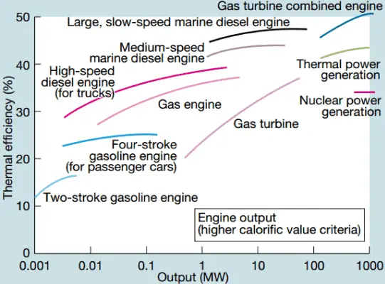
In general, the efficiency of even the best heat engines is quite low. In short, it is very difficult to convert thermal energy to mechanical energy. The thermal efficiencies are usually below 50% and often far below.
Takaishi, Tatsuo; Numata, Akira; Nakano, Ryouji; Sakaguchi, Katsuhiko (March 2008). “Approach to High Efficiency Diesel and Gas Engines” (PDF). Mitsubishi Heavy Industries Technical Review. 45 (1). Retrieved 2011-02-04.
It is easy to produce thermal energy by doing work, for example by any frictional process. But to get work from thermal energy is more difficult. It is closely associated with the concept of entropy, which quantifies the energy of a substance that is no longer available to perform useful work. For example, electricity is particularly useful since it has verylow entropy (is highly ordered) and can be converted into other forms of energy very efficiently. Be careful when you compare it with efficiencies of wind or hydro power (wind turbines are not heat engines), there is no energy conversion between the thermal and mechanical energy.
The thermal efficiency of various heat engines designed or used today has a large range:
For example:
Transportation
In the middle of twentieth century, a typical steam locomotive had a thermal efficiency of about 6%. That means for every 100 MJ of coal burned, 6 MJ of mechanical power were produced.
A typical gasoline automotive engine operates at around 25% to 30% of thermal efficiency. About 70-75% is rejected as waste heat without being converted into useful work, i.e. work delivered to wheels.
A typical diesel automotive engine operates at around 30% to 35%. In general, engines using the Diesel cycle are usually more efficient.
In 2014, new regulations were introduced for Formula 1 cars. These motorsport regulations have pushed teams to develop highly efficient power units. According to Mercedes, their power unit is now achieving more than 45% and close to 50% thermal efficiency, i.e. 45 – 50% of the potential energy in the fuel is delivered to wheels.
The diesel engine has the highest thermal efficiency of any practical combustion engine. Low-speed diesel engines (as used in ships) can have a thermal efficiency that exceeds 50%. The largest diesel engine in the world peaks at 51.7%.
Power Engineering
Ocean thermal energy conversion (OTEC). OTEC is very sophisticated heat engine that uses the temperature difference between cooler deep and warmer surface seawaters to run a low-pressure turbine. Since the temperature difference is low, about 20°C, its thermal efficiency is also very low, about 3%.
In modern nuclear power plants the overall thermal efficiency is about one-third (33%), so 3000 MWth of thermal power from the fission reaction is needed to generate 1000 MWe of electrical power. Higher efficiencies can be attained by increasing the temperature of the steam. But this requires an increase in pressures inside boilers or steam generators. However, metallurgical considerations place an upper limits on such pressures. In comparison to other energy sources the thermal efficiency of 33% is not much. But it must be noted that nuclear power plants are much more complex than fossil fuel power plants and it is much easier to burn fossil fuel ,than to generate energy from nuclear fuel.
Sub-critical fossil fuel power plants, that are operated under critical pressure (i.e. lower than 22.1 MPa), can achieve 36–40% efficiency.
Supercritical fossil fuel power plants, that are operated at supercritical pressure (i.e. greater than 22.1 MPa), have efficiencies around 43%. Most efficient and also very complex coal-fired power plants that are operated at “ultra critical” pressures (i.e. around 30 MPa) and use multiple stage reheat reach about 48% efficiency.
Modern Combined Cycle Gas Turbine (CCGT) plants, in which the thermodynamic cycle of consists of two power plant cycles (e.g. the Brayton cycle and the Rankine cycle), can achieve a thermal efficiency of around 55%, in contrast to a single cycle steam power plant which is limited to efficiencies of around 35-45%.
References:
Nuclear and Reactor Physics:
J. R. Lamarsh, Introduction to Nuclear Reactor Theory, 2nd ed., Addison-Wesley, Reading, MA (1983).
J. R. Lamarsh, A. J. Baratta, Introduction to Nuclear Engineering, 3d ed., Prentice-Hall, 2001, ISBN: 0-201-82498-1.
W. M. Stacey, Nuclear Reactor Physics, John Wiley & Sons, 2001, ISBN: 0- 471-39127-1.
We hope, this article, Heat Engine, helps you. If so, give us a like in the sidebar. Main purpose of this website is to help the public to learn some interesting and important information about thermal engineering.
Thermal efficiency, ηth, of any heat engine is defined as the ratio of the work to heat input. To calculate the thermal efficiency engineers often use enthalpy. Thermal Engineering
Thermal Efficiency
An ideal heat engine is an imaginary engine in which energy extracted as heat from the high-temperature reservoir is converted completely to work. But according to the Kelvin-Planck statement, such an engine would violate the second law of thermodynamics, because there must be losses in the conversion process. The net heat added to the system must be higher than the net work done by the system.
Kelvin-Planck statement:
“It is impossible to construct a device which operates on a cycle and produces no other effect than the production of work and the transfer of heat from a single body”.
Thermal Efficiency Formula
As a result of this statement, we define the thermal efficiency, ηth, of any heat engine as the ratio of the work it does, W, to the heat input at the high temperature, QH.
The thermal efficiency, ηth, represents the fraction of heat, QH, that is converted to work. It is a dimensionless performance measure of a heat engine that uses thermal energy, such as a steam turbine, an internal combustion engine, or a refrigerator. For a refrigeration or heat pumps, thermal efficiency indicates the extent to which the energy added by work is converted to net heat output. Since it is dimensionless number, we must always express W, QH, and QC in the same units.
Since energy is conserved according to the first law of thermodynamicsand energy cannot be be converted to work completely, the heat input, QH, must equal the work done, W, plus the heat that must be dissipated as waste heat QC into the environment. Therefore we can rewrite the formula for thermal efficiency as:
To give the efficiency as a percent, we multiply the previous formula by 100. Note that, ηth could be 100% only if the waste heat QC will be zero.
In general, the efficiency of even the best heat engines is quite low. In short, it is very difficult to convert thermal energy to mechanical energy. The thermal efficiencies are usually below 50% and often far below. Be careful when you compare it with efficiencies of wind or hydro power (wind turbines are not heat engines), there is no energy conversion between the thermal and mechanical energy.
Causes of Inefficiency
As was discussed, an efficiency can range between 0 and 1. Each heat engine is somehow inefficient. This inefficiency can be attributed to three causes.
Irreversibility of Processes. There is an overall theoretical upper limit to the efficiency of conversion of heat to work in any heat engine. This upper limit is called the Carnot efficiency. According to the Carnot principle, no engine can be more efficient than a reversible engine (a Carnot heat engine) operating between the same high temperature and low temperature reservoirs. For example, when the hot reservoir have Thot of 400°C (673K) and Tcold of about 20°C (293K), the maximum (ideal) efficiency will be: = 1 – Tcold/Thot = 1 – 293/673 = 56%. But all real thermodynamic processes are somehow irreversible. They are not done infinitely slowly. Therefore, heat engines must have lower efficiencies than limits on their efficiency due to the inherent irreversibility of the heat engine cycle they use.
Presence of Friction and Heat Losses. In real thermodynamic systems or in real heat engines, a part of the overall cycle inefficiency is due to the losses by the individual components. In real devices (such as turbines, pumps, and compressors) a mechanical friction, heat losses and losses in the combustion process cause further efficiency losses.
Design Inefficiency. Finally, last and also important source of inefficiencies is from the compromises made by engineers when designing a heat engine (e.g. power plant). They must consider cost and other factors in the design and operation of the cycle. As an example consider a design of the condenser in the thermal power plants. Ideally the steam exhausted into the condenser would have no subcooling. But real condensers are designed to subcool the liquid by a few degrees of Celsius in order to avoid the suction cavitation in the condensate pumps. But, this subcooling increases the inefficiency of the cycle, because more energy is needed to reheat the water.
Thermal Efficiency and the Second Law
The second law of thermodynamics may be expressed in many specific ways. Each statement expresses the same law. Listed below are three that are often encountered.
Before these statements, we have to remind the work of a French engineer and physicist, Nicolas Léonard Sadi Carnot advanced the study of the second law by forming a principle (also called Carnot’s rule) that specifies limits on the maximum efficiency any heat engine can obtain.
Carnot's Principle
In 1824, a French engineer and physicist, Nicolas Léonard Sadi Carnot advanced the study of the second law by forming a principle (also called Carnot’s rule) that specifies limits on the maximum efficiency any heat engine can obtain. In short, this principle states that the efficiency of a thermodynamic cycle depends solely on the difference between the hot and cold temperature reservoirs.
Carnot’s principle states:
No engine can be more efficient than a reversible engine (a Carnot heat engine) operating between the same high temperature and low temperature reservoirs.
The efficiencies of all reversible engines (Carnot heat engines) operating between the same constant temperature reservoirs are the same, regardless of the working substance employed or the operation details.
Carnot Efficiency
The formula for this maximum efficiency is:
where:
is the efficiency of Carnot cycle, i.e. it is the ratio = W/QH of the work done by the engine to the heat energy entering the system from the hot reservoir.
TC is the absolute temperature (Kelvins) of the cold reservoir,
TH is the absolute temperature (Kelvins) of the hot reservoir.
Example: Carnot efficiency for coal-fired power plant
In a modern coal-fired power plant, the temperature of high pressure steam (Thot) would be about 400°C (673K) and Tcold, the cooling tower water temperature, would be about 20°C (293K). For this type of power plant the maximum (ideal) efficiency will be:
= 1 – Tcold/Thot = 1 – 293/673 = 56%
It must be added, this is an idealized efficiency. The Carnot efficiency is valid for reversible processes. These processes cannot be achieved in real cycles of power plants. The Carnot efficiency dictates that higher efficiencies can be attained by increasing the temperature of the steam. This feature is valid also for real thermodynamic cycles. But this requires an increase in pressures inside boilers or steam generators. However, metallurgical considerations place an upper limits on such pressures. Sub-critical fossil fuel power plants, that are operated under critical pressure (i.e. lower than 22.1 MPa), can achieve 36–40% efficiency. Supercritical designs, that are operated at supercritical pressure (i.e. greater than 22.1 MPa), have efficiencies around 43%. Most efficient and also very complex coal-fired power plants that are operated at “ultra critical” pressures (i.e. around 30 MPa) and use multiple stage reheat reach about 48% efficiency.
In general, the efficiency of even the best heat engines is quite low. In short, it is very difficult to convert thermal energy to mechanical energy. The thermal efficiencies are usually below 50% and often far below.
Takaishi, Tatsuo; Numata, Akira; Nakano, Ryouji; Sakaguchi, Katsuhiko (March 2008). “Approach to High Efficiency Diesel and Gas Engines” (PDF). Mitsubishi Heavy Industries Technical Review. 45 (1). Retrieved 2011-02-04.
It is easy to produce thermal energy by doing work, for example by any frictional process. But to get work from thermal energy is more difficult. It is closely associated with the concept of entropy, which quantifies the energy of a substance that is no longer available to perform useful work. For example, electricity is particularly useful since it has verylow entropy (is highly ordered) and can be converted into other forms of energy very efficiently. Be careful when you compare it with efficiencies of wind or hydro power (wind turbines are not heat engines), there is no energy conversion between the thermal and mechanical energy.
The thermal efficiency of various heat engines designed or used today has a large range:
For example:
Transportation
In the middle of twentieth century, a typical steam locomotive had a thermal efficiency of about 6%. That means for every 100 MJ of coal burned, 6 MJ of mechanical power were produced.
A typical gasoline automotive engine operates at around 25% to 30% of thermal efficiency. About 70-75% is rejected as waste heat without being converted into useful work, i.e. work delivered to wheels.
A typical diesel automotive engine operates at around 30% to 35%. In general, engines using the Diesel cycle are usually more efficient.
In 2014, new regulations were introduced for Formula 1 cars. These motorsport regulations have pushed teams to develop highly efficient power units. According to Mercedes, their power unit is now achieving more than 45% and close to 50% thermal efficiency, i.e. 45 – 50% of the potential energy in the fuel is delivered to wheels.
The diesel engine has the highest thermal efficiency of any practical combustion engine. Low-speed diesel engines (as used in ships) can have a thermal efficiency that exceeds 50%. The largest diesel engine in the world peaks at 51.7%.
Power Engineering
Ocean thermal energy conversion (OTEC). OTEC is very sophisticated heat engine that uses the temperature difference between cooler deep and warmer surface seawaters to run a low-pressure turbine. Since the temperature difference is low, about 20°C, its thermal efficiency is also very low, about 3%.
In modern nuclear power plants the overall thermal efficiency is about one-third (33%), so 3000 MWth of thermal power from the fission reaction is needed to generate 1000 MWe of electrical power. Higher efficiencies can be attained by increasing the temperature of the steam. But this requires an increase in pressures inside boilers or steam generators. However, metallurgical considerations place an upper limits on such pressures. In comparison to other energy sources the thermal efficiency of 33% is not much. But it must be noted that nuclear power plants are much more complex than fossil fuel power plants and it is much easier to burn fossil fuel ,than to generate energy from nuclear fuel.
Sub-critical fossil fuel power plants, that are operated under critical pressure (i.e. lower than 22.1 MPa), can achieve 36–40% efficiency.
Supercritical fossil fuel power plants, that are operated at supercritical pressure (i.e. greater than 22.1 MPa), have efficiencies around 43%. Most efficient and also very complex coal-fired power plants that are operated at “ultra critical” pressures (i.e. around 30 MPa) and use multiple stage reheat reach about 48% efficiency.
Modern Combined Cycle Gas Turbine (CCGT) plants, in which the thermodynamic cycle of consists of two power plant cycles (e.g. the Brayton cycle and the Rankine cycle), can achieve a thermal efficiency of around 55%, in contrast to a single cycle steam power plant which is limited to efficiencies of around 35-45%.
Thermal Efficiency of Brayton Cycle
Let assume the ideal Brayton cycle that describes the workings of a constant pressureheat engine. Modern gas turbine engines and airbreathing jet engines also follow the Brayton cycle. This cycle consist of four thermodynamic processes:
Ideal Brayton cycle consist of four thermodynamic processes. Two isentropic processes and two isobaric processes.
isentropic compression – ambient air is drawn into the compressor, where it is pressurized (1 → 2). The work required for the compressor is given by WC = H2 – H1.
isobaric heat addition – the compressed air then runs through a combustion chamber, where fuel is burned and air or another medium is heated (2 → 3). It is a constant-pressure process, since the chamber is open to flow in and out. The net heat added is given by Qadd = H3 – H2
isentropic expansion – the heated, pressurized air then expands on turbine, gives up its energy. The work done by turbine is given by WT = H4 – H3
isobaric heat rejection – the residual heat must be rejected in order to close the cycle. The net heat rejected is given by Qre = H4 – H1
As can be seen, we can describe and calculate (e.g. thermodynamic efficiency) such cycles (similarly for Rankine cycle) using enthalpies.
To calculate the thermal efficiency of the Brayton cycle (single compressor and single turbine) engineers use the first law of thermodynamics in terms of enthalpy rather than in terms of internal energy.
In this equation the term Vdp is a flow process work. This work, Vdp, is used for open flow systems like a turbine or a pump in which there is a “dp”, i.e. change in pressure. There are no changes in control volume. As can be seen, this form of the law simplifies the description of energy transfer.
There are expressions in terms of more familiar variables such as temperature and pressure:
dH = CpdT + V(1-αT)dp
Where Cp is the heat capacity at constant pressure and α is the coefficient of (cubic) thermal expansion. For ideal gas αT = 1 and therefore:
dH = CpdT
At constant pressure, the enthalpy change equals the energy transferred from the environment through heating:
Isobaric process (Vdp = 0):
dH = dQ → Q = H2 – H1 → H2 – H1 = Cp (T2 – T1)
At constant entropy, i.e. in isentropic process, the enthalpy change equals the flow process work done on or by the system:
Isentropic process (dQ = 0):
dH = Vdp → W = H2 – H1 → H2 – H1 = Cp (T2 – T1)
Ideal Brayton cycle consist of four thermodynamic processes. Two isentropic processes and two isobaric processes.
The enthalpy can be made into an intensive, or specific, variable by dividing by the mass. Engineers use thespecific enthalpy in thermodynamic analysis more than the enthalpy itself. The thermal efficiency of such simple Brayton cycle, for ideal gas and in terms of specific enthalpies can now be expressed in terms of the temperatures:
Thermal Efficiency of Rankine Cycle
Rankine Cycle – Thermodynamics as Energy Conversion Science
The Rankine cycle closely describes the processes in steam-operated heat engines commonly found in most of thermal power plants. The heat sources used in these power plants are usually the combustion of fossil fuels such as coal, natural gas, or also the nuclear fission.
A nuclear power plant (nuclear power station) looks like a standard thermal power station with one exception. The heat source in the nuclear power plant is a nuclear reactor. As is typical in all conventional thermal power stations the heat is used to generate steam which drives a steam turbine connected to a generator which produces electricity.
Typically most of nuclear power plants operates multi-stage condensing steam turbines. In these turbines the high-pressure stage receives steam (this steam is nearly saturated steam – x = 0.995 – point C at the figure; 6 MPa; 275.6°C) from a steam generator and exhaust it to moisture separator-reheater (point D). The steam must be reheated in order to avoid damages that could be caused to blades of steam turbine by low quality steam. The reheater heats the steam (point D) and then the steam is directed to the low-pressure stage of steam turbine, where expands (point E to F). The exhausted steam then condenses in the condenser and it is at a pressure well below atmospheric (absolute pressure of 0.008 MPa), and is in a partially condensed state (point F), typically of a quality near 90%.
In this case, steam generators, steam turbine, condensers and feedwater pumps constitute a heat engine, that is subject to the efficiency limitations imposed by thesecond law of thermodynamics. In ideal case (no friction, reversible processes, perfect design), this heat engine would have a Carnot efficiency of
= 1 – Tcold/Thot = 1 – 315/549 = 42.6%
where the temperature of the hot reservoir is 275.6°C (548.7K), the temperature of the cold reservoir is 41.5°C (314.7K). But the nuclear power plant is the real heat engine, in which thermodynamic processes are somehow irreversible. They are not done infinitely slowly. In real devices (such as turbines, pumps, and compressors) a mechanical friction and heat losses cause further efficiency losses.
In this equation the term Vdp is a flow process work. This work, Vdp, is used for open flow systems like a turbine or a pump in which there is a “dp”, i.e. change in pressure. There are no changes in control volume. As can be seen, this form of the law simplifies the description of energy transfer. At constant pressure, the enthalpy change equals the energy transferred from the environment through heating:
Isobaric process (Vdp = 0):
dH = dQ → Q = H2 – H1
At constant entropy, i.e. in isentropic process, the enthalpy change equals the flow process work done on or by the system:
Isentropic process (dQ = 0):
dH = Vdp → W = H2 – H1
It is obvious, it will be very useful in analysis of both thermodynamic cycles used in power engineering, i.e. in Brayton cycle and Rankine cycle.
The enthalpy can be made into an intensive, or specific, variable by dividing by the mass. Engineers use thespecific enthalpy in thermodynamic analysis more than the enthalpy itself. It is tabulated in the steam tables along with specific volume and specific internal energy. The thermal efficiency of such simple Rankine cycle and in terms of specific enthalpies would be:
It is very simple equation and for determination of the thermal efficiency you can use data from steam tables.
In modern nuclear power plants the overall thermal efficiency is about one-third (33%), so 3000 MWth of thermal power from the fission reaction is needed to generate 1000 MWe of electrical power. The reason lies in relatively low steam temperature (6 MPa; 275.6°C). Higher efficiencies can be attained by increasing the temperature of the steam. But this requires an increase in pressures inside boilers or steam generators. However, metallurgical considerations place an upper limits on such pressures. In comparison to other energy sources the thermal efficiency of 33% is not much. But it must be noted that nuclear power plants are much more complex than fossil fuel power plants and it is much easier to burn fossil fuel ,than to generate energy from nuclear fuel. Sub-critical fossil fuel power plants, that are operated under critical pressure (i.e. lower than 22.1 MPa), can achieve 36–40% efficiency.
References:
Nuclear and Reactor Physics:
J. R. Lamarsh, Introduction to Nuclear Reactor Theory, 2nd ed., Addison-Wesley, Reading, MA (1983).
J. R. Lamarsh, A. J. Baratta, Introduction to Nuclear Engineering, 3d ed., Prentice-Hall, 2001, ISBN: 0-201-82498-1.
W. M. Stacey, Nuclear Reactor Physics, John Wiley & Sons, 2001, ISBN: 0- 471-39127-1.
We hope, this article, Thermal Efficiency, helps you. If so, give us a like in the sidebar. Main purpose of this website is to help the public to learn some interesting and important information about thermal engineering.
There are several types of heat engines. This article summarizes these types and includes an example of heat engine. Types of Heat Engines – Example of Heat Engine
Types of Heat Engines
In general, heat engines are categorized according to a combustion location as:
External combustion engine. For example, steam engines are external combustion engines, where the working fluid is separate from the combustion products.
Internal combustion engine. Typical example of internal combustion engine is an engine used in automobile, in which the high temperature is achieved by burning the gasoline-air mixture in the cylinder itself.
The detailed categorization is based on a working fluid used in thermodynamic cycle:
Gas Cycles. In these cycles the working fluid is always a gas. The Otto cycle and the Diesel cycle (used is automobiles) are also typical examples of gas-only cycles. Modern gas turbine engines and airbreathing jet engines also based on the gas-only cycle, they follow the Brayton cycle.
Liquid Cycles. Liquid-only cycles are rather exotic. In these cycles the working fluid is always a liquid. The Malone liquid engine is an example of liquid-only cycle. The Malone liquid engine was a modification of the Stirling cycle, using water as the working fluid instead of gas
Cycles with Phase Changes. Steam engines are typical examples of external engines with phase change of working fluid.
Example of Heat Engine
The Rankine cycle closely describes the processes in steam-operated heat engines commonly found in most of thermal power plants.
Steam engines and refrigerators are typical examples of external engines with phase change of working fluid. Typical thermodynamic cycle used to analyze this process is called the Rankine cycle, which usually uses water as the working fluid.
The Rankine cycle closely describes the processes in steam-operated heat engines commonly found in most of thermal power plants. The heat sources used in these power plants are usually the combustion of fossil fuels such as coal, natural gas, or also the nuclear fission.
A nuclear power plant (nuclear power station) looks like a standard thermal power station with one exception. The heat source in the nuclear power plant is a nuclear reactor. As is typical in all conventional thermal power stations the heat is used to generate steam which drives a steam turbine connected to a generator which produces electricity.
Rankine Cycle – Thermodynamics as Energy Conversion Science
Typically most of nuclear power plants operates multi-stage condensing steam turbines. In these turbines the high-pressure stage receives steam (this steam is nearly saturated steam – x = 0.995 – point C at the figure; 6 MPa; 275.6°C) from a steam generator and exhaust it to moisture separator-reheater (point D). The steam must be reheated in order to avoid damages that could be caused to blades of steam turbine by low quality steam. The reheater heats the steam (point D) and then the steam is directed to the low-pressure stage of steam turbine, where expands (point E to F). The exhausted steam then condenses in the condenser and it is at a pressure well below atmospheric (absolute pressure of 0.008 MPa), and is in a partially condensed state (point F), typically of a quality near 90%.
In this case, steam generators, steam turbine, condensers and feedwater pumps constitute a heat engine, that is subject to the efficiency limitations imposed by the second law of thermodynamics. In ideal case (no friction, reversible processes, perfect design), this heat engine would have a Carnot efficiency of
= 1 – Tcold/Thot = 1 – 315/549 = 42.6%
where the temperature of the hot reservoir is 275.6°C (548.7K), the temperature of the cold reservoir is 41.5°C (314.7K). But the nuclear power plant is the real heat engine, in which thermodynamic processes are somehow irreversible. They are not done infinitely slowly. In real devices (such as turbines, pumps, and compressors) a mechanical friction and heat losses cause further efficiency losses.
Therefore nuclear power plants usually have efficiency about 33%. In modern nuclear power plants the overall thermodynamic efficiency is about one-third (33%), so 3000 MWth of thermal power from the fission reaction is needed to generate 1000 MWe of electrical power.
According to the Carnot’s principle higher efficiencies can be attained by increasing the temperature of the steam. But this requires an increase in pressures inside boilers or steam generators. However, metallurgical considerations place an upper limits on such pressures. From this point of view, supercritical water reactors are considered a promising advancement for nuclear power plants because of its high thermal efficiency (~45 % vs. ~33 % for current LWRs). SCWRs are operated at supercritical pressure (i.e. greater than 22.1 MPa).
References:
Nuclear and Reactor Physics:
J. R. Lamarsh, Introduction to Nuclear Reactor Theory, 2nd ed., Addison-Wesley, Reading, MA (1983).
J. R. Lamarsh, A. J. Baratta, Introduction to Nuclear Engineering, 3d ed., Prentice-Hall, 2001, ISBN: 0-201-82498-1.
W. M. Stacey, Nuclear Reactor Physics, John Wiley & Sons, 2001, ISBN: 0- 471-39127-1.
Robert Reed Burn, Introduction to Nuclear Reactor Operation, 1988.
U.S. Department of Energy, Nuclear Physics and Reactor Theory. DOE Fundamentals Handbook, Volume 1 and 2. January 1993.
Advanced Reactor Physics:
K. O. Ott, W. A. Bezella, Introductory Nuclear Reactor Statics, American Nuclear Society, Revised edition (1989), 1989, ISBN: 0-894-48033-2.
K. O. Ott, R. J. Neuhold, Introductory Nuclear Reactor Dynamics, American Nuclear Society, 1985, ISBN: 0-894-48029-4.
D. L. Hetrick, Dynamics of Nuclear Reactors, American Nuclear Society, 1993, ISBN: 0-894-48453-2.
E. E. Lewis, W. F. Miller, Computational Methods of Neutron Transport, American Nuclear Society, 1993, ISBN: 0-894-48452-4.
See also:
Heat Engines
We hope, this article, Type of Heat Engines – Example of Heat Engine, helps you. If so, give us a like in the sidebar. Main purpose of this website is to help the public to learn some interesting and important information about thermal engineering.
Thermal efficiency formula represents the fraction of heat, QH, that is converted to work. Thermal efficiency equation is often expressed in terms of the temperatures or enthalpies. Thermal Engineering
Thermal Efficiency Formula
As a result of this statement, we define the thermal efficiency, ηth, of any heat engine as the ratio of the work it does, W, to the heat input at the high temperature, QH. The thermal efficiency formula is then:
The thermal efficiency, ηth, represents the fraction of heat, QH, that is converted to work. It is a dimensionless performance measure of a heat engine that uses thermal energy, such as a steam turbine, an internal combustion engine, or a refrigerator. For a refrigeration or heat pumps, thermal efficiency indicates the extent to which the energy added by work is converted to net heat output. Since it is dimensionless number, we must always express W, QH, and QC in the same units.
Since energy is conserved according to the first law of thermodynamicsand energy cannot be be converted to work completely, the heat input, QH, must equal the work done, W, plus the heat that must be dissipated as waste heat QC into the environment. Therefore we can rewrite the formula for thermal efficiency as:
To give the efficiency as a percent, we multiply the previous formula by 100. Note that, ηth could be 100% only if the waste heat QC will be zero.
In general, the efficiency of even the best heat engines is quite low. In short, it is very difficult to convert thermal energy to mechanical energy. The thermal efficiencies are usually below 50% and often far below. Be careful when you compare it with efficiencies of wind or hydro power (wind turbines are not heat engines), there is no energy conversion between the thermal and mechanical energy.
Carnot's Efficiency
In 1824, a French engineer and physicist, Nicolas Léonard Sadi Carnot advanced the study of the second law by forming a principle (also called Carnot’s rule) that specifies limits on the maximum efficiency any heat engine can obtain. In short, this principle states that the efficiency of a thermodynamic cycle depends solely on the difference between the hot and cold temperature reservoirs.
Carnot’s principle states:
No engine can be more efficient than a reversible engine (a Carnot heat engine) operating between the same high temperature and low temperature reservoirs.
The efficiencies of all reversible engines (Carnot heat engines) operating between the same constant temperature reservoirs are the same, regardless of the working substance employed or the operation details.
Carnot Efficiency
The formula for this maximum efficiency is:
where:
is the efficiency of Carnot cycle, i.e. it is the ratio = W/QH of the work done by the engine to the heat energy entering the system from the hot reservoir.
TC is the absolute temperature (Kelvins) of the cold reservoir,
TH is the absolute temperature (Kelvins) of the hot reservoir.
Formula for Brayton Cycle
Ideal Brayton cycle consist of four thermodynamic processes. Two isentropic processes and two isobaric processes.
The thermal efficiency of simple Brayton cycle, for ideal gas and in terms of specific enthalpies can be expressed in terms of the temperatures:
Thermal Efficiency of Rankine Cycle
The Rankine cycle closely describes the processes in steam-operated heat engines commonly found in most of thermal power plants.
The thermal efficiency of simple Rankine cycle and in terms of specific enthalpies is:
It is very simple equation and for determination of the thermal efficiency you can use data from steam tables.
References:
Nuclear and Reactor Physics:
J. R. Lamarsh, Introduction to Nuclear Reactor Theory, 2nd ed., Addison-Wesley, Reading, MA (1983).
J. R. Lamarsh, A. J. Baratta, Introduction to Nuclear Engineering, 3d ed., Prentice-Hall, 2001, ISBN: 0-201-82498-1.
W. M. Stacey, Nuclear Reactor Physics, John Wiley & Sons, 2001, ISBN: 0- 471-39127-1.
Robert Reed Burn, Introduction to Nuclear Reactor Operation, 1988.
U.S. Department of Energy, Nuclear Physics and Reactor Theory. DOE Fundamentals Handbook, Volume 1 and 2. January 1993.
Advanced Reactor Physics:
K. O. Ott, W. A. Bezella, Introductory Nuclear Reactor Statics, American Nuclear Society, Revised edition (1989), 1989, ISBN: 0-894-48033-2.
K. O. Ott, R. J. Neuhold, Introductory Nuclear Reactor Dynamics, American Nuclear Society, 1985, ISBN: 0-894-48029-4.
D. L. Hetrick, Dynamics of Nuclear Reactors, American Nuclear Society, 1993, ISBN: 0-894-48453-2.
E. E. Lewis, W. F. Miller, Computational Methods of Neutron Transport, American Nuclear Society, 1993, ISBN: 0-894-48452-4.
See also:
Thermal Efficiency
We hope, this article, Thermal Efficiency Formula, helps you. If so, give us a like in the sidebar. Main purpose of this website is to help the public to learn some interesting and important information about thermal engineering.
Causes of Inefficiency. Each heat engine is somehow inefficient. This inefficiency can be attributed to three causes. Irreversibility of Processes. Presence of Friction. Design Inefficiency. Thermal Engineering
Causes of Inefficiency
As was discussed, an efficiency can range between 0 and 1. Each heat engine is somehow inefficient. This inefficiency can be attributed to three causes.
Irreversibility of Processes. There is an overall theoretical upper limit to the efficiency of conversion of heat to work in any heat engine. This upper limit is called the Carnot efficiency. According to the Carnot principle, no engine can be more efficient than a reversible engine (a Carnot heat engine) operating between the same high temperature and low temperature reservoirs. For example, when the hot reservoir have Thot of 400°C (673K) and Tcold of about 20°C (293K), the maximum (ideal) efficiency will be: = 1 – Tcold/Thot = 1 – 293/673 = 56%. But all real thermodynamic processes are somehow irreversible. They are not done infinitely slowly. Therefore, heat engines must have lower efficiencies than limits on their efficiency due to the inherent irreversibility of the heat engine cycle they use.
Presence of Friction and Heat Losses. In real thermodynamic systems or in real heat engines, a part of the overall cycle inefficiency is due to the losses by the individual components. In real devices (such as turbines, pumps, and compressors) a mechanical friction, heat losses and losses in the combustion process cause further efficiency losses.
Design Inefficiency. Finally, last and also important source of inefficiencies is from the compromises made by engineers when designing a heat engine (e.g. power plant). They must consider cost and other factors in the design and operation of the cycle. As an example consider a design of the condenser in the thermal power plants. Ideally the steam exhausted into the condenser would have no subcooling. But real condensers are designed to subcool the liquid by a few degrees of Celsius in order to avoid the suction cavitation in the condensate pumps. But, this subcooling increases the inefficiency of the cycle, because more energy is needed to reheat the water.
Thermal Efficiency and the Second Law
The second law of thermodynamics may be expressed in many specific ways. Each statement expresses the same law. Listed below are three that are often encountered.
Before these statements, we have to remind the work of a French engineer and physicist, Nicolas Léonard Sadi Carnot advanced the study of the second law by forming a principle (also called Carnot’s rule) that specifies limits on the maximum efficiency any heat engine can obtain.
Carnot's Principle
In 1824, a French engineer and physicist, Nicolas Léonard Sadi Carnot advanced the study of the second law by forming a principle (also called Carnot’s rule) that specifies limits on the maximum efficiency any heat engine can obtain. In short, this principle states that the efficiency of a thermodynamic cycle depends solely on the difference between the hot and cold temperature reservoirs.
Carnot’s principle states:
No engine can be more efficient than a reversible engine (a Carnot heat engine) operating between the same high temperature and low temperature reservoirs.
The efficiencies of all reversible engines (Carnot heat engines) operating between the same constant temperature reservoirs are the same, regardless of the working substance employed or the operation details.
Carnot Efficiency
The formula for this maximum efficiency is:
where:
is the efficiency of Carnot cycle, i.e. it is the ratio = W/QH of the work done by the engine to the heat energy entering the system from the hot reservoir.
TC is the absolute temperature (Kelvins) of the cold reservoir,
TH is the absolute temperature (Kelvins) of the hot reservoir.
Example: Carnot efficiency for coal-fired power plant
In a modern coal-fired power plant, the temperature of high pressure steam (Thot) would be about 400°C (673K) and Tcold, the cooling tower water temperature, would be about 20°C (293K). For this type of power plant the maximum (ideal) efficiency will be:
= 1 – Tcold/Thot = 1 – 293/673 = 56%
It must be added, this is an idealized efficiency. The Carnot efficiency is valid for reversible processes. These processes cannot be achieved in real cycles of power plants. The Carnot efficiency dictates that higher efficiencies can be attained by increasing the temperature of the steam. This feature is valid also for real thermodynamic cycles. But this requires an increase in pressures inside boilers or steam generators. However, metallurgical considerations place an upper limits on such pressures. Sub-critical fossil fuel power plants, that are operated under critical pressure (i.e. lower than 22.1 MPa), can achieve 36–40% efficiency. Supercritical designs, that are operated at supercritical pressure (i.e. greater than 22.1 MPa), have efficiencies around 43%. Most efficient and also very complex coal-fired power plants that are operated at “ultra critical” pressures (i.e. around 30 MPa) and use multiple stage reheat reach about 48% efficiency.
Robert Reed Burn, Introduction to Nuclear Reactor Operation, 1988.
U.S. Department of Energy, Nuclear Physics and Reactor Theory. DOE Fundamentals Handbook, Volume 1 and 2. January 1993.
Advanced Reactor Physics:
K. O. Ott, W. A. Bezella, Introductory Nuclear Reactor Statics, American Nuclear Society, Revised edition (1989), 1989, ISBN: 0-894-48033-2.
K. O. Ott, R. J. Neuhold, Introductory Nuclear Reactor Dynamics, American Nuclear Society, 1985, ISBN: 0-894-48029-4.
D. L. Hetrick, Dynamics of Nuclear Reactors, American Nuclear Society, 1993, ISBN: 0-894-48453-2.
E. E. Lewis, W. F. Miller, Computational Methods of Neutron Transport, American Nuclear Society, 1993, ISBN: 0-894-48452-4.
See also:
Thermal Efficiency
We hope, this article, Cause of Inefficiency – Thermal Efficiency, helps you. If so, give us a like in the sidebar. Main purpose of this website is to help the public to learn some interesting and important information about thermal engineering.
The thermal efficiency of heat engines designed or used today has a large range. Thermal efficiency of typical nuclear power plant is about one-third (33%). Thermal Engineering
Thermal Efficiency of Heat Engines
In general, the efficiency of even the best heat engines is quite low. In short, it is very difficult to convert thermal energy to mechanical energy. The thermal efficiencies are usually below 50% and often far below.
Takaishi, Tatsuo; Numata, Akira; Nakano, Ryouji; Sakaguchi, Katsuhiko (March 2008). “Approach to High Efficiency Diesel and Gas Engines” (PDF). Mitsubishi Heavy Industries Technical Review. 45 (1). Retrieved 2011-02-04.
It is easy to produce thermal energy by doing work, for example by any frictional process. But to get work from thermal energy is more difficult. It is closely associated with the concept of entropy, which quantifies the energy of a substance that is no longer available to perform useful work. For example, electricity is particularly useful since it has verylow entropy (is highly ordered) and can be converted into other forms of energy very efficiently. Be careful when you compare it with efficiencies of wind or hydro power (wind turbines are not heat engines), there is no energy conversion between the thermal and mechanical energy.
The thermal efficiency of various heat engines designed or used today has a large range:
For example:
Transportation
In the middle of twentieth century, a typical steam locomotive had a thermal efficiency of about 6%. That means for every 100 MJ of coal burned, 6 MJ of mechanical power were produced.
A typical gasoline automotive engine operates at around 25% to 30% of thermal efficiency. About 70-75% is rejected as waste heat without being converted into useful work, i.e. work delivered to wheels.
A typical diesel automotive engine operates at around 30% to 35%. In general, engines using the Diesel cycle are usually more efficient.
In 2014, new regulations were introduced for Formula 1 cars. These motorsport regulations have pushed teams to develop highly efficient power units. According to Mercedes, their power unit is now achieving more than 45% and close to 50% thermal efficiency, i.e. 45 – 50% of the potential energy in the fuel is delivered to wheels.
The diesel engine has the highest thermal efficiency of any practical combustion engine. Low-speed diesel engines (as used in ships) can have a thermal efficiency that exceeds 50%. The largest diesel engine in the world peaks at 51.7%.
Power Engineering
Ocean thermal energy conversion (OTEC). OTEC is very sophisticated heat engine that uses the temperature difference between cooler deep and warmer surface seawaters to run a low-pressure turbine. Since the temperature difference is low, about 20°C, its thermal efficiency is also very low, about 3%.
In modern nuclear power plants the overall thermal efficiency is about one-third (33%), so 3000 MWth of thermal power from the fission reaction is needed to generate 1000 MWe of electrical power. Higher efficiencies can be attained by increasing the temperature of the steam. But this requires an increase in pressures inside boilers or steam generators. However, metallurgical considerations place an upper limits on such pressures. In comparison to other energy sources the thermal efficiency of 33% is not much. But it must be noted that nuclear power plants are much more complex than fossil fuel power plants and it is much easier to burn fossil fuel ,than to generate energy from nuclear fuel.
Sub-critical fossil fuel power plants, that are operated under critical pressure (i.e. lower than 22.1 MPa), can achieve 36–40% efficiency.
Supercritical fossil fuel power plants, that are operated at supercritical pressure (i.e. greater than 22.1 MPa), have efficiencies around 43%. Most efficient and also very complex coal-fired power plants that are operated at “ultra critical” pressures (i.e. around 30 MPa) and use multiple stage reheat reach about 48% efficiency.
Modern Combined Cycle Gas Turbine (CCGT) plants, in which the thermodynamic cycle of consists of two power plant cycles (e.g. the Brayton cycle and the Rankine cycle), can achieve a thermal efficiency of around 55%, in contrast to a single cycle steam power plant which is limited to efficiencies of around 35-45%.
Example: Carnot efficiency for coal-fired power plant
In a modern coal-fired power plant, the temperature of high pressure steam (Thot) would be about 400°C (673K) and Tcold, the cooling tower water temperature, would be about 20°C (293K). For this type of power plant the maximum (ideal) efficiency will be:
= 1 – Tcold/Thot = 1 – 293/673 = 56%
It must be added, this is an idealized efficiency. The Carnot efficiency is valid for reversible processes. These processes cannot be achieved in real cycles of power plants. The Carnot efficiency dictates that higher efficiencies can be attained by increasing the temperature of the steam. This feature is valid also for real thermodynamic cycles. But this requires an increase in pressures inside boilers or steam generators. However, metallurgical considerations place an upper limits on such pressures. Sub-critical fossil fuel power plants, that are operated under critical pressure (i.e. lower than 22.1 MPa), can achieve 36–40% efficiency. Supercritical designs, that are operated at supercritical pressure (i.e. greater than 22.1 MPa), have efficiencies around 43%. Most efficient and also very complex coal-fired power plants that are operated at “ultra critical” pressures (i.e. around 30 MPa) and use multiple stage reheat reach about 48% efficiency.
Let assume the ideal Brayton cycle that describes the workings of a constant pressureheat engine. Modern gas turbine engines and airbreathing jet engines also follow the Brayton cycle. This cycle consist of four thermodynamic processes:
Ideal Brayton cycle consist of four thermodynamic processes. Two isentropic processes and two isobaric processes.
isentropic compression – ambient air is drawn into the compressor, where it is pressurized (1 → 2). The work required for the compressor is given by WC = H2 – H1.
isobaric heat addition – the compressed air then runs through a combustion chamber, where fuel is burned and air or another medium is heated (2 → 3). It is a constant-pressure process, since the chamber is open to flow in and out. The net heat added is given by Qadd = H3 – H2
isentropic expansion – the heated, pressurized air then expands on turbine, gives up its energy. The work done by turbine is given by WT = H4 – H3
isobaric heat rejection – the residual heat must be rejected in order to close the cycle. The net heat rejected is given by Qre = H4 – H1
As can be seen, we can describe and calculate (e.g. thermodynamic efficiency) such cycles (similarly for Rankine cycle) using enthalpies.
To calculate the thermal efficiency of the Brayton cycle (single compressor and single turbine) engineers use the first law of thermodynamics in terms of enthalpy rather than in terms of internal energy.
In this equation the term Vdp is a flow process work. This work, Vdp, is used for open flow systems like a turbine or a pump in which there is a “dp”, i.e. change in pressure. There are no changes in control volume. As can be seen, this form of the law simplifies the description of energy transfer.
There are expressions in terms of more familiar variables such as temperature and pressure:
dH = CpdT + V(1-αT)dp
Where Cp is the heat capacity at constant pressure and α is the coefficient of (cubic) thermal expansion. For ideal gas αT = 1 and therefore:
dH = CpdT
At constant pressure, the enthalpy change equals the energy transferred from the environment through heating:
Isobaric process (Vdp = 0):
dH = dQ → Q = H2 – H1 → H2 – H1 = Cp (T2 – T1)
At constant entropy, i.e. in isentropic process, the enthalpy change equals the flow process work done on or by the system:
Isentropic process (dQ = 0):
dH = Vdp → W = H2 – H1 → H2 – H1 = Cp (T2 – T1)
Ideal Brayton cycle consist of four thermodynamic processes. Two isentropic processes and two isobaric processes.
The enthalpy can be made into an intensive, or specific, variable by dividing by the mass. Engineers use thespecific enthalpy in thermodynamic analysis more than the enthalpy itself. The thermal efficiency of such simple Brayton cycle, for ideal gas and in terms of specific enthalpies can now be expressed in terms of the temperatures:
Thermal Efficiency of Rankine Cycle
Rankine Cycle – Thermodynamics as Energy Conversion Science
The Rankine cycle closely describes the processes in steam-operated heat engines commonly found in most of thermal power plants. The heat sources used in these power plants are usually the combustion of fossil fuels such as coal, natural gas, or also the nuclear fission.
A nuclear power plant (nuclear power station) looks like a standard thermal power station with one exception. The heat source in the nuclear power plant is a nuclear reactor. As is typical in all conventional thermal power stations the heat is used to generate steam which drives a steam turbine connected to a generator which produces electricity.
Typically most of nuclear power plants operates multi-stage condensing steam turbines. In these turbines the high-pressure stage receives steam (this steam is nearly saturated steam – x = 0.995 – point C at the figure; 6 MPa; 275.6°C) from a steam generator and exhaust it to moisture separator-reheater (point D). The steam must be reheated in order to avoid damages that could be caused to blades of steam turbine by low quality steam. The reheater heats the steam (point D) and then the steam is directed to the low-pressure stage of steam turbine, where expands (point E to F). The exhausted steam then condenses in the condenser and it is at a pressure well below atmospheric (absolute pressure of 0.008 MPa), and is in a partially condensed state (point F), typically of a quality near 90%.
In this case, steam generators, steam turbine, condensers and feedwater pumps constitute a heat engine, that is subject to the efficiency limitations imposed by thesecond law of thermodynamics. In ideal case (no friction, reversible processes, perfect design), this heat engine would have a Carnot efficiency of
= 1 – Tcold/Thot = 1 – 315/549 = 42.6%
where the temperature of the hot reservoir is 275.6°C (548.7K), the temperature of the cold reservoir is 41.5°C (314.7K). But the nuclear power plant is the real heat engine, in which thermodynamic processes are somehow irreversible. They are not done infinitely slowly. In real devices (such as turbines, pumps, and compressors) a mechanical friction and heat losses cause further efficiency losses.
In this equation the term Vdp is a flow process work. This work, Vdp, is used for open flow systems like a turbine or a pump in which there is a “dp”, i.e. change in pressure. There are no changes in control volume. As can be seen, this form of the law simplifies the description of energy transfer. At constant pressure, the enthalpy change equals the energy transferred from the environment through heating:
Isobaric process (Vdp = 0):
dH = dQ → Q = H2 – H1
At constant entropy, i.e. in isentropic process, the enthalpy change equals the flow process work done on or by the system:
Isentropic process (dQ = 0):
dH = Vdp → W = H2 – H1
It is obvious, it will be very useful in analysis of both thermodynamic cycles used in power engineering, i.e. in Brayton cycle and Rankine cycle.
The enthalpy can be made into an intensive, or specific, variable by dividing by the mass. Engineers use thespecific enthalpy in thermodynamic analysis more than the enthalpy itself. It is tabulated in the steam tables along with specific volume and specific internal energy. The thermal efficiency of such simple Rankine cycle and in terms of specific enthalpies would be:
It is very simple equation and for determination of the thermal efficiency you can use data from steam tables.
In modern nuclear power plants the overall thermal efficiency is about one-third (33%), so 3000 MWth of thermal power from the fission reaction is needed to generate 1000 MWe of electrical power. The reason lies in relatively low steam temperature (6 MPa; 275.6°C). Higher efficiencies can be attained by increasing the temperature of the steam. But this requires an increase in pressures inside boilers or steam generators. However, metallurgical considerations place an upper limits on such pressures. In comparison to other energy sources the thermal efficiency of 33% is not much. But it must be noted that nuclear power plants are much more complex than fossil fuel power plants and it is much easier to burn fossil fuel ,than to generate energy from nuclear fuel. Sub-critical fossil fuel power plants, that are operated under critical pressure (i.e. lower than 22.1 MPa), can achieve 36–40% efficiency.
References:
Nuclear and Reactor Physics:
J. R. Lamarsh, Introduction to Nuclear Reactor Theory, 2nd ed., Addison-Wesley, Reading, MA (1983).
J. R. Lamarsh, A. J. Baratta, Introduction to Nuclear Engineering, 3d ed., Prentice-Hall, 2001, ISBN: 0-201-82498-1.
W. M. Stacey, Nuclear Reactor Physics, John Wiley & Sons, 2001, ISBN: 0- 471-39127-1.
Robert Reed Burn, Introduction to Nuclear Reactor Operation, 1988.
U.S. Department of Energy, Nuclear Physics and Reactor Theory. DOE Fundamentals Handbook, Volume 1 and 2. January 1993.
Advanced Reactor Physics:
K. O. Ott, W. A. Bezella, Introductory Nuclear Reactor Statics, American Nuclear Society, Revised edition (1989), 1989, ISBN: 0-894-48033-2.
K. O. Ott, R. J. Neuhold, Introductory Nuclear Reactor Dynamics, American Nuclear Society, 1985, ISBN: 0-894-48029-4.
D. L. Hetrick, Dynamics of Nuclear Reactors, American Nuclear Society, 1993, ISBN: 0-894-48453-2.
E. E. Lewis, W. F. Miller, Computational Methods of Neutron Transport, American Nuclear Society, 1993, ISBN: 0-894-48452-4.
See also:
Thermal Efficiency
We hope, this article, Thermal Efficiency of Heat Engines – Examples, helps you. If so, give us a like in the sidebar. Main purpose of this website is to help the public to learn some interesting and important information about thermal engineering.
Calculation of Thermal Efficiency. To calculate the thermal efficiency of the thermodynamic cycles engineers use the first law of thermodynamics in terms of enthalpy. Thermal Engineering
Calculation of Thermal Efficiency
As a result of this statement, we define the thermal efficiency, ηth, of any heat engine as the ratio of the work it does, W, to the heat input at the high temperature, QH.
The thermal efficiency, ηth, represents the fraction of heat, QH, that is converted to work. It is a dimensionless performance measure of a heat engine that uses thermal energy, such as a steam turbine, an internal combustion engine, or a refrigerator. For a refrigeration or heat pumps, thermal efficiency indicates the extent to which the energy added by work is converted to net heat output. Since it is dimensionless number, we must always express W, QH, and QC in the same units.
Since energy is conserved according to the first law of thermodynamicsand energy cannot be be converted to work completely, the heat input, QH, must equal the work done, W, plus the heat that must be dissipated as waste heat QC into the environment. Therefore we can rewrite the formula for thermal efficiency as:
To give the efficiency as a percent, we multiply the previous formula by 100. Note that, ηth could be 100% only if the waste heat QC will be zero.
In general, the efficiency of even the best heat engines is quite low. In short, it is very difficult to convert thermal energy to mechanical energy. The thermal efficiencies are usually below 50% and often far below. Be careful when you compare it with efficiencies of wind or hydro power (wind turbines are not heat engines), there is no energy conversion between the thermal and mechanical energy.
Calculation of Brayton Cycle
Let assume the ideal Brayton cycle that describes the workings of a constant pressureheat engine. Modern gas turbine engines and airbreathing jet engines also follow the Brayton cycle. This cycle consist of four thermodynamic processes:
Ideal Brayton cycle consist of four thermodynamic processes. Two isentropic processes and two isobaric processes.
isentropic compression – ambient air is drawn into the compressor, where it is pressurized (1 → 2). The work required for the compressor is given by WC = H2 – H1.
isobaric heat addition – the compressed air then runs through a combustion chamber, where fuel is burned and air or another medium is heated (2 → 3). It is a constant-pressure process, since the chamber is open to flow in and out. The net heat added is given by Qadd = H3 – H2
isentropic expansion – the heated, pressurized air then expands on turbine, gives up its energy. The work done by turbine is given by WT = H4 – H3
isobaric heat rejection – the residual heat must be rejected in order to close the cycle. The net heat rejected is given by Qre = H4 – H1
As can be seen, we can describe and calculate (e.g. thermodynamic efficiency) such cycles (similarly for Rankine cycle) using enthalpies.
To calculate the thermal efficiency of the Brayton cycle (single compressor and single turbine) engineers use the first law of thermodynamics in terms of enthalpy rather than in terms of internal energy.
In this equation the term Vdp is a flow process work. This work, Vdp, is used for open flow systems like a turbine or a pump in which there is a “dp”, i.e. change in pressure. There are no changes in control volume. As can be seen, this form of the law simplifies the description of energy transfer.
There are expressions in terms of more familiar variables such as temperature and pressure:
dH = CpdT + V(1-αT)dp
Where Cp is the heat capacity at constant pressure and α is the coefficient of (cubic) thermal expansion. For ideal gas αT = 1 and therefore:
dH = CpdT
At constant pressure, the enthalpy change equals the energy transferred from the environment through heating:
Isobaric process (Vdp = 0):
dH = dQ → Q = H2 – H1 → H2 – H1 = Cp (T2 – T1)
At constant entropy, i.e. in isentropic process, the enthalpy change equals the flow process work done on or by the system:
Isentropic process (dQ = 0):
dH = Vdp → W = H2 – H1 → H2 – H1 = Cp (T2 – T1)
Ideal Brayton cycle consist of four thermodynamic processes. Two isentropic processes and two isobaric processes.
The enthalpy can be made into an intensive, or specific, variable by dividing by the mass. Engineers use thespecific enthalpy in thermodynamic analysis more than the enthalpy itself. The thermal efficiency of such simple Brayton cycle, for ideal gas and in terms of specific enthalpies can now be expressed in terms of the temperatures:
Calculation of Rankine Cycle
Rankine Cycle – Thermodynamics as Energy Conversion Science
The Rankine cycle closely describes the processes in steam-operated heat engines commonly found in most of thermal power plants. The heat sources used in these power plants are usually the combustion of fossil fuels such as coal, natural gas, or also the nuclear fission.
A nuclear power plant (nuclear power station) looks like a standard thermal power station with one exception. The heat source in the nuclear power plant is a nuclear reactor. As is typical in all conventional thermal power stations the heat is used to generate steam which drives a steam turbine connected to a generator which produces electricity.
Typically most of nuclear power plants operates multi-stage condensing steam turbines. In these turbines the high-pressure stage receives steam (this steam is nearly saturated steam – x = 0.995 – point C at the figure; 6 MPa; 275.6°C) from a steam generator and exhaust it to moisture separator-reheater (point D). The steam must be reheated in order to avoid damages that could be caused to blades of steam turbine by low quality steam. The reheater heats the steam (point D) and then the steam is directed to the low-pressure stage of steam turbine, where expands (point E to F). The exhausted steam then condenses in the condenser and it is at a pressure well below atmospheric (absolute pressure of 0.008 MPa), and is in a partially condensed state (point F), typically of a quality near 90%.
In this case, steam generators, steam turbine, condensers and feedwater pumps constitute a heat engine, that is subject to the efficiency limitations imposed by thesecond law of thermodynamics. In ideal case (no friction, reversible processes, perfect design), this heat engine would have a Carnot efficiency of
= 1 – Tcold/Thot = 1 – 315/549 = 42.6%
where the temperature of the hot reservoir is 275.6°C (548.7K), the temperature of the cold reservoir is 41.5°C (314.7K). But the nuclear power plant is the real heat engine, in which thermodynamic processes are somehow irreversible. They are not done infinitely slowly. In real devices (such as turbines, pumps, and compressors) a mechanical friction and heat losses cause further efficiency losses.
In this equation the term Vdp is a flow process work. This work, Vdp, is used for open flow systems like a turbine or a pump in which there is a “dp”, i.e. change in pressure. There are no changes in control volume. As can be seen, this form of the law simplifies the description of energy transfer. At constant pressure, the enthalpy change equals the energy transferred from the environment through heating:
Isobaric process (Vdp = 0):
dH = dQ → Q = H2 – H1
At constant entropy, i.e. in isentropic process, the enthalpy change equals the flow process work done on or by the system:
Isentropic process (dQ = 0):
dH = Vdp → W = H2 – H1
It is obvious, it will be very useful in analysis of both thermodynamic cycles used in power engineering, i.e. in Brayton cycle and Rankine cycle.
The enthalpy can be made into an intensive, or specific, variable by dividing by the mass. Engineers use thespecific enthalpy in thermodynamic analysis more than the enthalpy itself. It is tabulated in the steam tables along with specific volume and specific internal energy. The thermal efficiency of such simple Rankine cycle and in terms of specific enthalpies would be:
It is very simple equation and for determination of the thermal efficiency you can use data from steam tables.
In modern nuclear power plants the overall thermal efficiency is about one-third (33%), so 3000 MWth of thermal power from the fission reaction is needed to generate 1000 MWe of electrical power. The reason lies in relatively low steam temperature (6 MPa; 275.6°C). Higher efficiencies can be attained by increasing the temperature of the steam. But this requires an increase in pressures inside boilers or steam generators. However, metallurgical considerations place an upper limits on such pressures. In comparison to other energy sources the thermal efficiency of 33% is not much. But it must be noted that nuclear power plants are much more complex than fossil fuel power plants and it is much easier to burn fossil fuel ,than to generate energy from nuclear fuel. Sub-critical fossil fuel power plants, that are operated under critical pressure (i.e. lower than 22.1 MPa), can achieve 36–40% efficiency.
References:
Nuclear and Reactor Physics:
J. R. Lamarsh, Introduction to Nuclear Reactor Theory, 2nd ed., Addison-Wesley, Reading, MA (1983).
J. R. Lamarsh, A. J. Baratta, Introduction to Nuclear Engineering, 3d ed., Prentice-Hall, 2001, ISBN: 0-201-82498-1.
W. M. Stacey, Nuclear Reactor Physics, John Wiley & Sons, 2001, ISBN: 0- 471-39127-1.
Robert Reed Burn, Introduction to Nuclear Reactor Operation, 1988.
U.S. Department of Energy, Nuclear Physics and Reactor Theory. DOE Fundamentals Handbook, Volume 1 and 2. January 1993.
Advanced Reactor Physics:
K. O. Ott, W. A. Bezella, Introductory Nuclear Reactor Statics, American Nuclear Society, Revised edition (1989), 1989, ISBN: 0-894-48033-2.
K. O. Ott, R. J. Neuhold, Introductory Nuclear Reactor Dynamics, American Nuclear Society, 1985, ISBN: 0-894-48029-4.
D. L. Hetrick, Dynamics of Nuclear Reactors, American Nuclear Society, 1993, ISBN: 0-894-48453-2.
E. E. Lewis, W. F. Miller, Computational Methods of Neutron Transport, American Nuclear Society, 1993, ISBN: 0-894-48452-4.
See also:
Thermal Efficiency
We hope, this article, Calculation of Thermal Efficiency, helps you. If so, give us a like in the sidebar. Main purpose of this website is to help the public to learn some interesting and important information about thermal engineering.