Momentum Formula – Momentum Equation
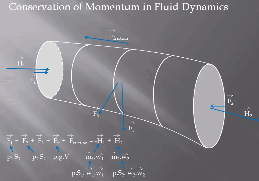 We assume fluid to be both steady and incompressible. To determine the rate of change of momentum for a fluid we will consider a streamtube (control volume) as we did for the Bernoulli equation. In this control volume any change in momentum of the fluid within a control volume is due to the action of external forces on the fluid within the volume.
As can be seen from the picture the control volume method can be used to analyze the law of conservation of momentum in fluid. Control volume is an imaginary surface enclosing a volume of interest. The control volume can be fixed or moving, and it can be rigid or deformable. In order to determine all forces acting on the surfaces of the control volume we have to solve the conservation laws in this control volume.
The first conservation equation we have to consider in the control volume is the continuity equation (the law of conservation of matter). In the simplest form it is represented by following equation:
∑ṁin = ∑ṁout
Sum of mass flow rates entering per unit time = Sum of mass flow rates leaving per unit time
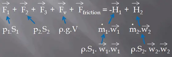
The second conservation equation we have to consider in the control volume is the momentum formula.In the simplest form the momentum formula can be represented by following equation:
–
Choosing a Control Volume
A control volume can be selected as any arbitrary volume through which fluid flows. This volume can be static, moving, and even deforming during flow. In order to solve any problem we have to solve basic conservation laws in this volume. It is very important to know all relative flow velocities to the control surface and therefore it is very important to define exactly the boundaries of the control volume during an analysis.
Example: The force acting on a deflector elbow
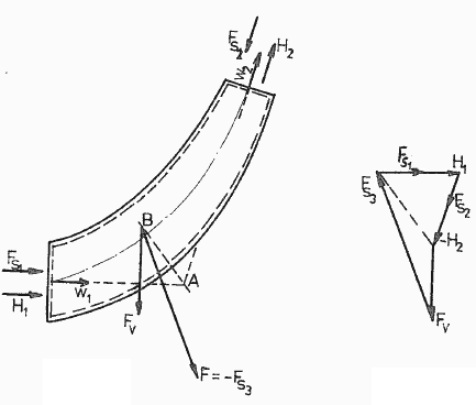 An elbow (let say of primary piping) is used to deflect water flow at a velocity of 17 m/s. The piping diameter is equal to 700 mm. The gauge pressure inside the pipe is about 16 MPa at the temperature of 290°C. Fluid is of constant density ⍴ ~ 720 kg/m3 (at 290°C). The angle of the elbow is 45°.
Calculate the force on the wall of a deflector elbow (i.e. calculate vector F3).
Assumptions:
- The flow is steady.
- The frictional losses are negligible.
- The weight of the elbow is negligible.
- The weight of the water in the elbow is negligible.
We take the elbow as the control volume. The control volume is shown at the picture. The momentum equation is a vector equation so it has three components. We take the x- and z- coordinates as shown and we will solve the problem separately according to these coordinates.
First, let us consider the component in the x-coordinate. The conservation of linear momentum equation becomes:
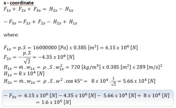
Second, let us consider the component in the y-coordinate. The conservation of linear momentum equation becomes:
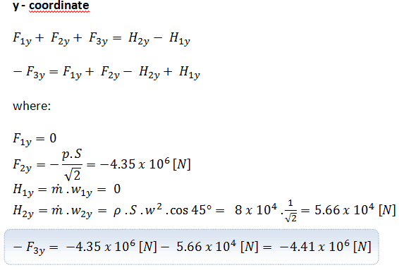
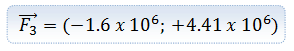
The final force acting on the wall of a deflector elbow will be:
Example: Water Jet Striking a Stationary Plate
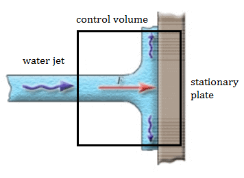 A stationary plate (e.g. blade of a watermill) is used to deflect water flow at a velocity of 1 m/s and at an angle of 90°. It occurs at atmospheric pressure and the mass flow rate is equal to Q =1 m3/s.
- Calculate the pressure force.
- Calculate the body force.
- Calculate the total force.
- Calculate the resultant force.
Solution
- The pressure force is zero as the pressure at both the inlet and the outlets to the control volume are atmospheric.
- As the control volume is small we can ignore the body force due to the weight of gravity.
- Fx = ρ.Q.(w1x – w2x) = 1000 . 1 . (1 – 0) = 1000 N
Fy = 0
F = (1000, 0) - The resultant force on the plane is the same magnitude but in the opposite direction as the total force F (friction and weight are neglected).
The water jet exerts on the plate the force of 1000 N in the x-direction.
We hope, this article, Momentum Formula – Momentum Equation, helps you. If so, give us a like in the sidebar. Main purpose of this website is to help the public to learn some interesting and important information about thermal engineering.