Facebook Instagram Youtube Twitter

What is Regenerative Heat Exchanger – Definition

Regenerative Heat Exchanger. Regenerator is a type of heat exchanger where heat from the hot fluid is intermittently stored in a thermal storage medium before it is transferred to the cold fluid. Thermal Engineering

Regenerative Heat Exchanger

In general, the heat exchangers used in regeneration may be classified as either regenerators or recuperators.

  • Regenerator (Regenerative Heat Exchanger) is a type of heat exchanger where heat from the hot fluid is intermittently stored in a thermal storage medium before it is transferred to the cold fluid. It has a single flow path in which the hot and cold fluids alternately pass through.
  • Recuperator is a type of heat exchanger has separate flow paths for each fluid along their own passages and heat is transferred through the separating walls. Recuperators (e.g. economisers) are often used in power engineering, to increase the overall efficiency of thermodynamic cycles. For example, in a gas turbine engine. The recuperator transfers some of the waste heat in the exhaust to the compressed air, thus preheating it before entering the combustion chamber. Many recuperators are designed as counter-flow heat exchangers.

Heat Regeneration

In steam turbines theory,  significant increases in the thermal efficiency of steam turbine can be achieved through reducing the amount of fuel that must be added in the boiler. This can be done by transferring heat (e.g. partially expanded steam) from certain sections of the steam turbine, which is normally well above the ambient temperature, to the feedwater. This process is known as heat regeneration and a variety of heat regenerators can be used for this purpose. Sometimes engineers use the term economiser that are heat exchangers intended to reduce energy consumption, especially in case of preheating of a fluid.

As can be seen in the article “Steam Generator”, the feedwater (secondary circuit) at the inlet of the steam generator may have about ~230°C (446°F)and then is heated to the boiling point of that fluid (280°C; 536°F; 6,5MPa)and evaporated. But the condensate at the condenser outlet may have about 40°C, so the heat regeneration in typical PWR is significant and very important:

  • Heat regeneration increases the thermal efficiency, since more of the heat flow into the cycle occurs at higher temperature.
  • Heat regeneration causes a decrease in the mass flow rate through low-pressure stage of the steam turbine, thus increases LP Isentropic Turbine Efficiency. Note that at the last stage of expansion the steam has very high specific volume.
  • Heat regeneration causes an increases in working steam quality, since the drains are situated at the periphery of turbine casing, where is higher concentration of water droplets.

Analysis of Heat Exchangers

Heat exchangers are commonly used in industry, and proper design of a heat exchanger depends on many variables. In the analysis of heat exchangers,  it is often convenient to work with an overall heat transfer coefficient, known as a U-factor. The U-factor is defined by an expression analogous to Newton’s law of cooling. Moreover, engineers also use the logarithmic mean temperature difference (LMTD) to determine the temperature driving force for heat transfer in heat exchangers.

Special Reference: John R. Thome, Engineering Data Book III. Wolverine Tube Inc. 2004.


References:
Heat Transfer:
  1. Fundamentals of Heat and Mass Transfer, 7th Edition. Theodore L. Bergman, Adrienne S. Lavine, Frank P. Incropera. John Wiley & Sons, Incorporated, 2011. ISBN: 9781118137253.
  2. Heat and Mass Transfer. Yunus A. Cengel. McGraw-Hill Education, 2011. ISBN: 9780071077866.
  3. U.S. Department of Energy, Thermodynamics, Heat Transfer and Fluid Flow. DOE Fundamentals Handbook, Volume 2 of 3. May 2016.

Nuclear and Reactor Physics:

  1. J. R. Lamarsh, Introduction to Nuclear Reactor Theory, 2nd ed., Addison-Wesley, Reading, MA (1983).
  2. J. R. Lamarsh, A. J. Baratta, Introduction to Nuclear Engineering, 3d ed., Prentice-Hall, 2001, ISBN: 0-201-82498-1.
  3. W. M. Stacey, Nuclear Reactor Physics, John Wiley & Sons, 2001, ISBN: 0- 471-39127-1.
  4. Glasstone, Sesonske. Nuclear Reactor Engineering: Reactor Systems Engineering, Springer; 4th edition, 1994, ISBN: 978-0412985317
  5. W.S.C. Williams. Nuclear and Particle Physics. Clarendon Press; 1 edition, 1991, ISBN: 978-0198520467
  6. G.R.Keepin. Physics of Nuclear Kinetics. Addison-Wesley Pub. Co; 1st edition, 1965
  7. Robert Reed Burn, Introduction to Nuclear Reactor Operation, 1988.
  8. U.S. Department of Energy, Nuclear Physics and Reactor Theory. DOE Fundamentals Handbook, Volume 1 and 2. January 1993.
  9. Paul Reuss, Neutron Physics. EDP Sciences, 2008. ISBN: 978-2759800414.

Advanced Reactor Physics:

  1. K. O. Ott, W. A. Bezella, Introductory Nuclear Reactor Statics, American Nuclear Society, Revised edition (1989), 1989, ISBN: 0-894-48033-2.
  2. K. O. Ott, R. J. Neuhold, Introductory Nuclear Reactor Dynamics, American Nuclear Society, 1985, ISBN: 0-894-48029-4.
  3. D. L. Hetrick, Dynamics of Nuclear Reactors, American Nuclear Society, 1993, ISBN: 0-894-48453-2.
  4. E. E. Lewis, W. F. Miller, Computational Methods of Neutron Transport, American Nuclear Society, 1993, ISBN: 0-894-48452-4.

See also:

Heat Exchangers

We hope, this article, Regenerative Heat Exchanger, helps you. If so, give us a like in the sidebar. Main purpose of this website is to help the public to learn some interesting and important information about thermal engineering.
What is Heat Generation – Definition

It is essential, that the heat generation – heat removal rate balance must be maintained to prevent these temperatures that might result in the failure of fuel or other structural materials. Thermal Engineering

Heat Generation in Nuclear Reactors

As was written, a nuclear power plant (nuclear power station) looks like a standard thermal power station with one exception. The heat source in the nuclear power plant is a nuclear reactor. As is typical in all conventional thermal power stations the heat is used to generate steam which drives a steam turbine connected to a generator which produces electricity. But in nuclear power plants reactors produce enormous amount of heat (energy) in a small volume. The density of the energy generation is very large and this puts demands on its heat transfer system (reactor coolant system).

Power Distribution - Nuclear Reactor
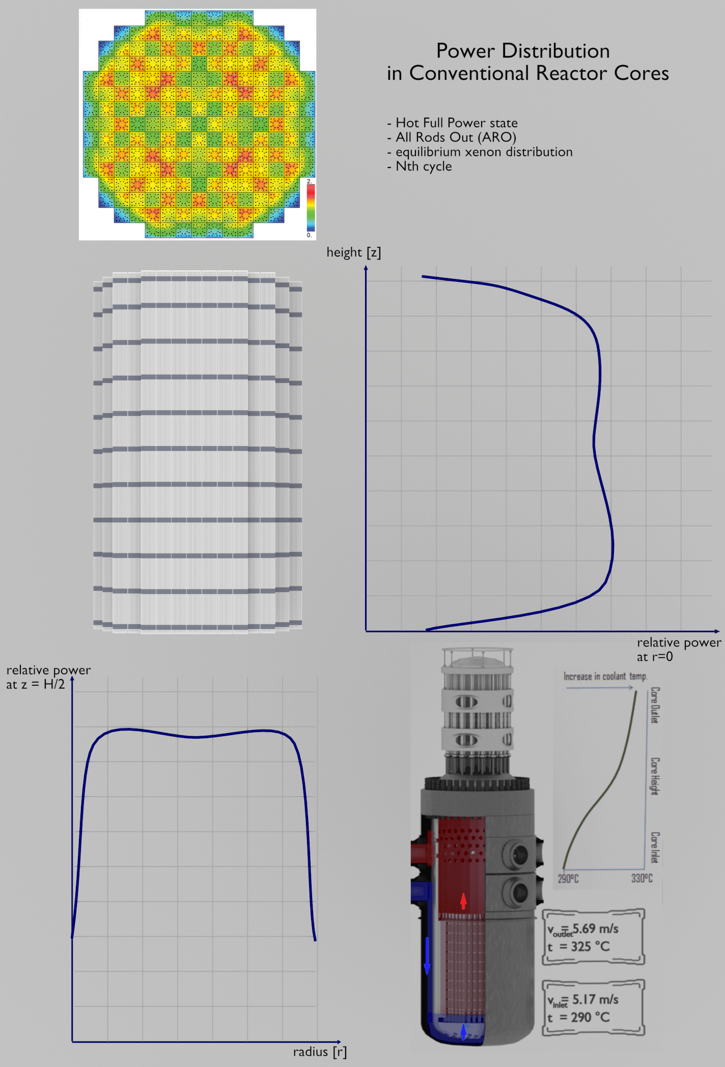
In commercial reactor cores the flux distribution is significantly influenced by many factors. Simply, there is no cosine and J0 in the commercial power reactor at power operation.

For a reactor to operate in a steady state, all of the heat released in the system must be removed as fast as it is produced. This is accomplished by passing a liquid or gaseous coolant through the core and through other regions where heat is generated. The heat transfer must be equal to or greater than the heat generation rate or overheating and possible damage to the fuel may occur. The nature and operation of this coolant system is one of the most important considerations in the design of a nuclear reactor.

It should be noted that from a strictly nuclear standpoint, there is theoretically no upper limit to the reactor thermal power, which can be attained by any critical reactor having sufficient excess of reactivity to overcome its negative temperature feedbacks. In each nuclear reactor, there is a direct proportionality between the neutron flux and the reactor thermal power. The term thermal power is usually used, because it means the rate at which heat is produced in the reactor core as the result of fissions in the fuel. Moreover, for a short period, a critical reactor does not need to have high excess of reactivity as in case of rapid reactivity excursions.

In short, almost any reactor is able to exceed the ability of heat removal of its coolant system. Beyond this point, the fuel would heat up and can reach very high temperatures. This situation must be avoided by reactor operator and by reactor safety systems. It is essential, that the heat generation – heat removal rate balance must be maintained to prevent these temperatures that might result in the failure of fuel or other structural materials. In reactor engineering, the thermal-hydraulics of nuclear reactors describe the effort involving the coupling of heat transfer and fluid dynamics to accomplish the desired heat removal rate from the core under both normal operation and accident conditions.

Heat Production in Fuel Elements

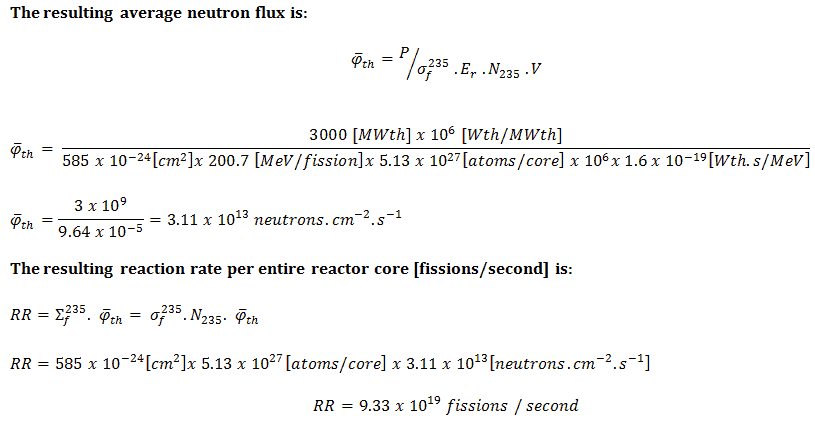
In nuclear reactors, there is a direct proportionality between the neutron flux and the reactor thermal power. This proporcionality is determined by the fission reaction rate per unit volume (RR = Ф . Σ). The fission reaction rate within a nuclear reactor is controlled by several factors. For simplicity let assume that the fissionable material is uniformly distributed in the reactor. In this case, the macroscopic cross-sections are independent of position. Multiplying the fission reaction rate per unit volume (RR = Ф . Σ) by the total volume of the core (V) gives us the total number of reactions occurring in the reactor core per unit time. But we also know the amount of energy released per one fission reaction to be about 200 MeV/fission. Now, it is possible to determine the rate of energy release (power) due to the fission reaction. It is given by following equation:

P = RR . Er . V = Ф . Σf . Er . V = Ф . NU235 . σf235 . Er . V

where:

P – reactor power (MeV.s-1)

Ф – neutron flux (neutrons.cm-2.s-1)

σ – microscopic cross section (cm2)

N – atomic number density (atoms.cm-3)

Er – the average recoverable energy per fission (MeV / fission)

V – total volume of the core (m3)

 
Reaction Rate and Reactor Power
A typical thermal reactor contains about 100 tons of uranium with an average enrichment of 2% (do not confuse it with the enrichment of the fresh fuel). If the reactor power is 3000MWth, determine the reaction rate and the average core thermal flux.

Solution:

The amount of fissile 235U per the volume of the reactor core.

m235 [g/core] = 100 [metric tons] x 0.02 [g of 235U / g of U] . 106 [g/metric ton] = 2 x 10⁶ grams of 235U per the volume of the reactor core

The atomic number density of 235U in the volume of the reactor core:

N235 . V = m235 . NA / M235
= 2 x 10⁶ [g 235 / core] x 6.022 x 10²³ [atoms/mol] / 235 [g/mol] = 5.13 x 1027 atoms / core
The microscopic fission cross-section of 235U (for thermal neutrons):

σf235 = 585 barns

The average recoverable energy per 235U fission:

Er = 200.7 MeV/fission

Neutron Flux - Reaction Rate - Thermal Reactor

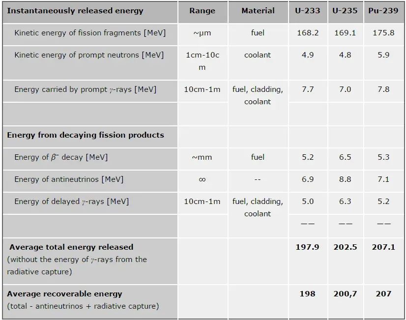
In general, the nuclear fission results in the release of enormous quantities of energy. The amount of energy depends strongly on the nucleus to be fissioned and also depends strongly on the kinetic energy of an incident neutron. In order to calculate the power of a reactor, it is necessary to be able precisely identify the individual components of this energy. At first, it is important to distinguish between the total energy released and the energy that can be recovered in a reactor.

Energy release per fissionThe total energy released in fission can be calculated from binding energies of initial target nucleus to be fissioned and binding energies of fission products. But not all the total energy can be recovered in a reactor. For example, about 10 MeV is released in the form of neutrinos (in fact antineutrinos). Since the neutrinos are weakly interacting (with extremely low cross-section of any interaction), they do not contribute to the energy that can be recovered in a reactor.

As can be seen from the table, the total energy released in a reactor is about 210 MeV per 235U fission, distributed as shown in the table. In a reactor, the average recoverable energy per fission is about 200 MeV, being the total energy minus the energy of the energy of antineutrinos that are radiated away. This means that about 3.1⋅1010 fissions per second are required to produce a power of 1 W. Since 1 gram of any fissile material contains about 2.5 x 10²¹ nuclei, the fissioning of 1 gram of fissile material yields about 1 megawatt-day (MWd) of heat energy.

Nuclear Power - Decay Heat
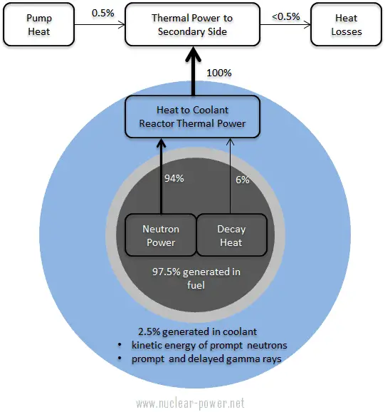
Thermal energy sources in power operation of pressurized water reactor

As can be seen from the description of the individual components of the total energy energy released during the fission reaction, there is significant amount of energy generated outside the nuclear fuel (outside fuel rods). Especially the kinetic energy of prompt neutrons is largely generated in the coolant (moderator). This phenomena needs to be included in the nuclear calculations.

Neutron Reflector
Neutron reflector inside a reactor core of LWR. It is only an illustrative example.

For LWR, it is generally accepted that about 2.5% of total energy is recovered in the moderator. This fraction of energy depends on the materials, their arrangement within the reactor, and thus on the reactor type.

It must be also added, also the other reactor internals must be cooled sufficiently in order to prevent overheating of thir construction materials. One of most exposed components is the neutron reflector, especially the heavy reflector. While acting as a neutron shield, the heavy reflector is heated due to absorption of the gamma radiation. In order to avoid overheating, the heat in the reflector is removed by water flowing through cooling channels drilled through the reflector.

See also: Energy release per fission

See also: Residual Heat

 
Heat Generation - Microscopic View
See also: Interaction of Heavy Charged Particles

Nuclear-Fission-minSince the electromagnetic interaction extends over some distance, it is not necessary for the light or heavy charged particle to make a direct collision with an atom. They can transfer energy simply by passing close by. Heavy charged particles, such as fission fragments or alpha particles interact with matter primarily through coulomb forces between their positive charge and the negative charge of the electrons from atomic orbitals. On the other hand, the internal energy of an atom is quantised, therefore only certain amount of energy can be transferred. In general, charged particles transfer energy mostly by:

  • Excitation. The charged particle can transfer energy to the atom, raising electrons to a higher energy levels.
  • Ionization. Ionization can occur, when the charged particle have enough energy to remove an electron. This results in a creation of ion pairs in surrounding matter.

Creation of pairs requires energy, which is lost from the kinetic energy of the charged particle causing it to decelerate. The positive ions and free electrons created by the passage of the charged particle will then reunite, releasing energy in the form of heat (e.g. vibrational energy or rotational energy of atoms). This is the principle how fission fragments heat up fuel in the reactor core. There are considerable differences in the ways of energy loss and scattering between the passage of light charged particles such as positrons and electrons and heavy charged particles such as fission fragments, alpha particles, muons. Most of these differences are based on the different dynamics of the collision process. In general, when a heavy particle collides with a much lighter particle (electrons in the atomic orbitals), the laws of energy and momentum conservation predict that only a small fraction of the massive particle’s energy can be transferred to the less massive particle. The actual amount of transferred energy depends on how closely the charged particles passes through the atom and it depends also on restrictions from quantisation of energy levels.

The distance required to bring the particle to rest is referred to as its range. The range of fission fragments in solids amounts to only a few microns, and thus most of the energy of fission is converted to heat very close to the point of fission. In case of gases the range increases to a few centimeters in dependence of gas parameters (density, type of gas etc.)  The trajectory of heavy charged particles are not greatly affected, because they interacts with light atomic electrons. Other charged particles, such as the alpha particles behave similarly with one exception – for lighter charged particles the ranges are somewhat longer.

Power Distribution in Conventional Reactor Cores

It should be noted the flux shape derived from the diffusion theory is only a theoretical case in a uniform homogeneous cylindrical reactor at low power levels (at “zero power criticality”). We have implicitly assumed that the core consisting of thousands of fuel and control elements, coolant, and structure can be represented by some effective homogeneous mixture. This is a very strong assumption, because it does not take into account the heterogeneity of a core.

See also: Diffusion Equation – Finite Cylindrical Reactor

In commercial reactor cores the flux distribution is significantly influenced by many factors. One of the most important aspects is the heterogeneity of fuel-moderator assembly. This problem is very complex and is described separately in:

See also: Power Distribution

Thermal Limits

The temperature in an operating reactor varies from point to point within the system. As a consequence, there is always one fuel rod and one local volume, that are hotter than all the rest. In order to limit these hot places the peak power limits must be introduced. The peak power limits are associated with such phenomena as the departure from nucleate boiling and with the conditions which could cause fuel pellet melt.

Therefore power distribution within the core must be properly limited. These limitations are usually divided into two basic categories:

Reactor Coolant delta T – Energy Balance

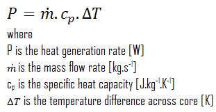
Another very useful relation is that the thermal power produced by a reactor is directly related to the mass flow rate of the reactor coolant and the temperature difference across the core.

energy balance equation - reactor

On a straight thermodynamic basis, this heat generation is also related to the fluid temperature difference across the core and the mass flow rate of the fluid passing through the core. Thus, the size of the reactor core is dependent upon and limited by low much liquid can be passed through the core to remove the generated thermal energy. Note that, in PWRs, the core outlet temperature is limited. In a typical pressurized water reactor, the hot primary coolant (water 330°C; 626°F) is pumped into the steam generator through primary inlet. This requires maintaining of very high pressures to keep the water in the liquid state. In order to prevent boiling of the primary coolant and to provide a subcooling margin (the difference between the pressurizer temperature and the highest temperature in the reactor core), pressures around 16 MPa are typical for PWRs. The reactor pressure vessel is the key component, which limits the thermal efficiency of each nuclear power plant, since the reactor vessel must withstand high pressures. Many other factors affect the amount of heat generated within a reactor core, but its limiting generation rate is based upon how much energy can safely be carried away by the coolant.

Temperature Profile – Nuclear Fuel

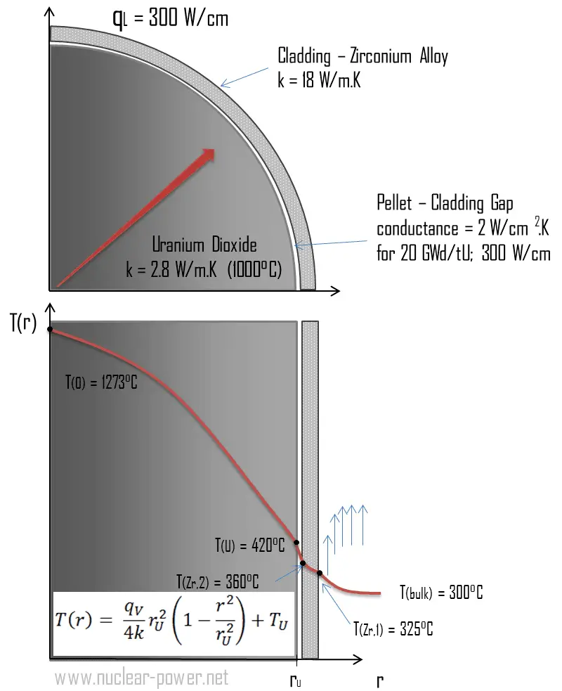
Nuclear Fuel - TemperaturesSee also: Cladding Surface Temperature

Most of PWRs use the uranium fuel, which is in the form of uranium dioxide. Uranium dioxide is a black semiconducting solid with very low thermal conductivity. On the other hand the uranium dioxide has very high melting point and has well known behavior. The UO2 is pressed into cylindrical pellets, these pellets are then sintered into the solid.

These cylindrical pellets are then loaded and encapsulated within a fuel rod (or fuel pin), which is made of zirconium alloys due to its very low absorption cross-section (unlike the stainless steel). The surface of the tube, which covers the pellets, is called fuel cladding.

See also: Thermal Conduction of Uranium Dioxide

Thermal and mechanical behavior of fuel pellets and fuel rods constitute one of three key core design disciplines. Nuclear fuel is operated under very inhospitable conditions (thermal, radiation, mechanical) and must withstand more than normal conditions operation. For example temperatures in the centre of fuel pellets reach more than 1000°C (1832°F) accompanied by fission-gas releases. Therefore detailed knowledge of temperature distribution within a single fuel rod is essential for safe operation of nuclear fuel. In this section we will study heat conduction equation in cylindrical coordinates using Dirichlet boundary condition with given surface temperature (i.e. using Dirichlet boundary condition). Comprehensive analysis of fuel rod temperature profile will be studied in separate section.

Temperature in the centerline of a fuel pellet

Consider the fuel pellet of radius rU = 0.40 cm, in which there is uniform and constant heat generation per unit volume, qV [W/m3]. Instead of volumetric heat rate qV [W/m3], engineers often use the linear heat rate, qL [W/m], which represents the heat rate of one meter of fuel rod. The linear heat rate can be calculated from the volumetric heat rate by:

linear heat rate vs volumetric heat rate

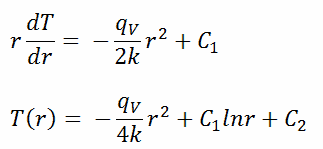
The centreline is taken as the origin for r-coordinate. Due to symmetry in z-direction and in azimuthal direction, we can separate of variables and simplify this problem to one-dimensional problem. Thus, we will solve for the temperature as function of radius, T(r), only. For constant thermal conductivity, k, the appropriate form of the cylindrical heat equation, is:

heat equation - cylindrical - 2

The general solution of this equation is:

heat equation - cylindrical - general solution

where C1 and C2 are the constants of integration.

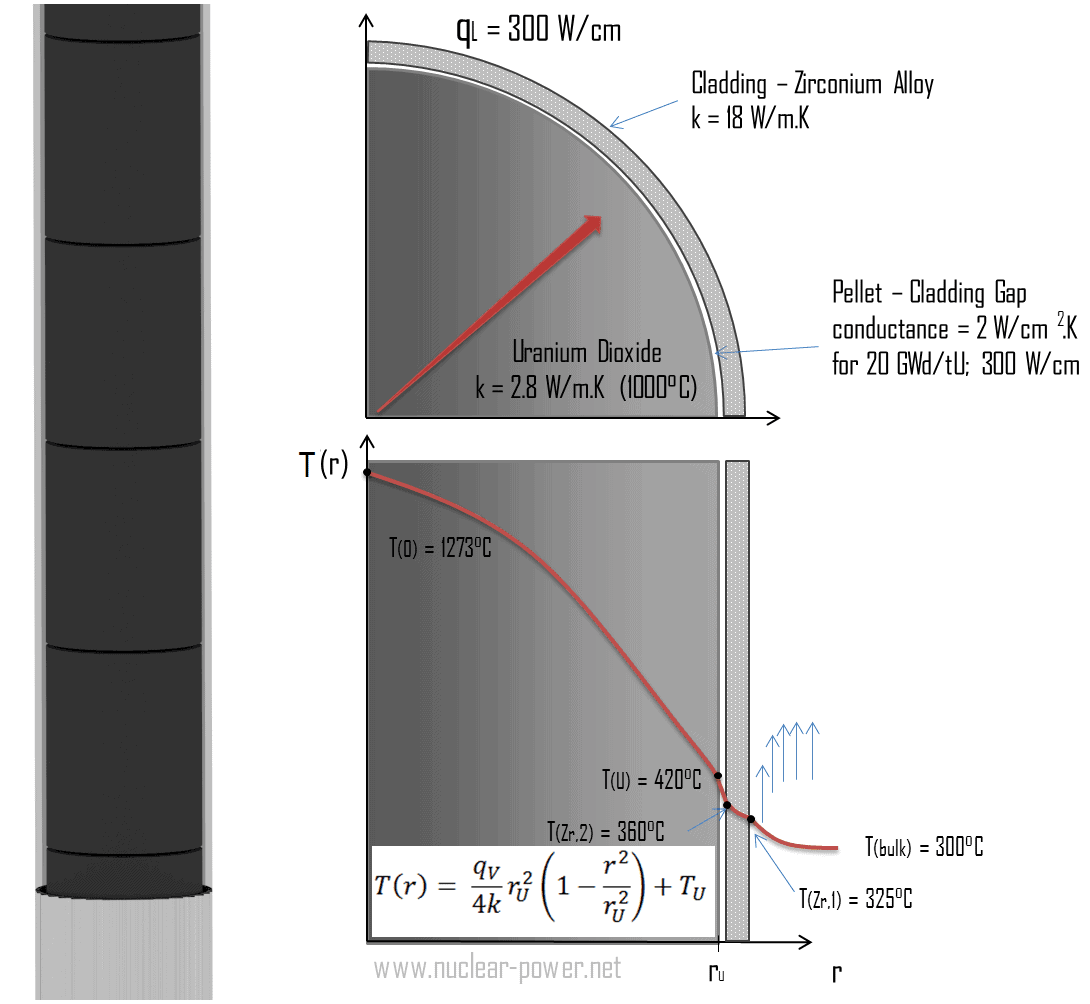
Thermal conduction - fuel pelletCalculate the temperature distribution, T(r), in this fuel pellet, if:

  • the temperatures at the surface of the fuel pellet is TU = 420°C
  • the fuel pellet radius rU = 4 mm.
  • the averaged material’s conductivity is k = 2.8 W/m.K (corresponds to uranium dioxide at 1000°C)
  • the linear heat rate is qL = 300 W/cm and thus the volumetric heat rate is qV = 597 x 106 W/m3

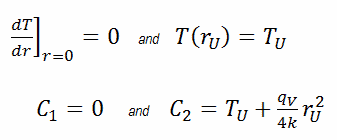
In this case, the surface is maintained at given temperatures TU. This corresponds to the Dirichlet boundary condition. Moreover, this problem is thermally symmetric and therefore we may use also thermal symmetry boundary condition. The constants may be evaluated using substitution into the general solution and are of the form:

heat equation - cylindrical - boundary conditions

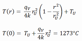
The resulting temperature distribution and the centerline (r = 0) temperature (maximum) in this cylindrical fuel pellet at these specific boundary conditions will be:

heat equation - cylindrical - solution

The radial heat flux at any radius, qr [W.m-1], in the cylinder may, of course, be determined by using the temperature distribution and with the Fourier’s law. Note that, with heat generation the heat flux is no longer independent of r.

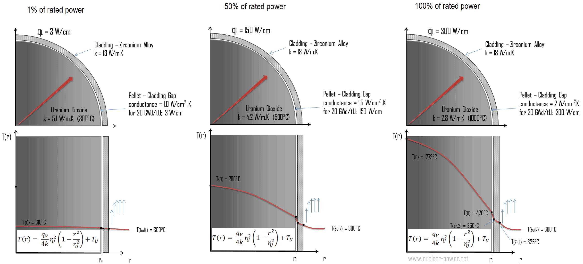
The following figure shows the temperature distribution in the fuel pellet at various power levels.

Temperature distribution - nuclear fuel

______

The temperature in an operating reactor varies from point to point within the system. As a consequence, there is always one fuel rod and one local volume, that are hotter than all the rest. In order to limit these hot places the peak power limits must be introduced. The peak power limits are associated with a boiling crisis and with the conditions which could cause fuel pellet melt. However, metallurgical considerations place an upper limits on the temperature of the fuel cladding and the fuel pellet. Above these temperatures there is a danger that the fuel may be damaged. One of the major objectives in the design of a nuclear reactors is to provide for the removal of the heat produced at the desired power level, while assuring that the maximum fuel temperature and the maximum cladding temperature are always below these predetermined values.

 
References:
Heat Transfer:
  1. Fundamentals of Heat and Mass Transfer, 7th Edition. Theodore L. Bergman, Adrienne S. Lavine, Frank P. Incropera. John Wiley & Sons, Incorporated, 2011. ISBN: 9781118137253.
  2. Heat and Mass Transfer. Yunus A. Cengel. McGraw-Hill Education, 2011. ISBN: 9780071077866.
  3. U.S. Department of Energy, Thermodynamics, Heat Transfer and Fluid Flow. DOE Fundamentals Handbook, Volume 2 of 3. May 2016.

Nuclear and Reactor Physics:

  1. J. R. Lamarsh, Introduction to Nuclear Reactor Theory, 2nd ed., Addison-Wesley, Reading, MA (1983).
  2. J. R. Lamarsh, A. J. Baratta, Introduction to Nuclear Engineering, 3d ed., Prentice-Hall, 2001, ISBN: 0-201-82498-1.
  3. W. M. Stacey, Nuclear Reactor Physics, John Wiley & Sons, 2001, ISBN: 0- 471-39127-1.
  4. Glasstone, Sesonske. Nuclear Reactor Engineering: Reactor Systems Engineering, Springer; 4th edition, 1994, ISBN: 978-0412985317
  5. W.S.C. Williams. Nuclear and Particle Physics. Clarendon Press; 1 edition, 1991, ISBN: 978-0198520467
  6. G.R.Keepin. Physics of Nuclear Kinetics. Addison-Wesley Pub. Co; 1st edition, 1965
  7. Robert Reed Burn, Introduction to Nuclear Reactor Operation, 1988.
  8. U.S. Department of Energy, Nuclear Physics and Reactor Theory. DOE Fundamentals Handbook, Volume 1 and 2. January 1993.
  9. Paul Reuss, Neutron Physics. EDP Sciences, 2008. ISBN: 978-2759800414.

Advanced Reactor Physics:

  1. K. O. Ott, W. A. Bezella, Introductory Nuclear Reactor Statics, American Nuclear Society, Revised edition (1989), 1989, ISBN: 0-894-48033-2.
  2. K. O. Ott, R. J. Neuhold, Introductory Nuclear Reactor Dynamics, American Nuclear Society, 1985, ISBN: 0-894-48029-4.
  3. D. L. Hetrick, Dynamics of Nuclear Reactors, American Nuclear Society, 1993, ISBN: 0-894-48453-2.
  4. E. E. Lewis, W. F. Miller, Computational Methods of Neutron Transport, American Nuclear Society, 1993, ISBN: 0-894-48452-4.

See also:

Heat Transfer

We hope, this article, Heat Generation, helps you. If so, give us a like in the sidebar. Main purpose of this website is to help the public to learn some interesting and important information about thermal engineering.
What is Heat Production in Fuel Elements – Definition

Heat Production in Fuel Elements. In fuel elements, heat is produced by various mechanisms. This article describes heat production in typical fuel elements. Thermal Engineering

Heat Production in Fuel Elements

In nuclear reactors, there is a direct proportionality between the neutron flux and the reactor thermal power. This proporcionality is determined by the fission reaction rate per unit volume (RR = Ф . Σ). The fission reaction rate within a nuclear reactor is controlled by several factors. For simplicity let assume that the fissionable material is uniformly distributed in the reactor. In this case, the macroscopic cross-sections are independent of position. Multiplying the fission reaction rate per unit volume (RR = Ф . Σ) by the total volume of the core (V) gives us the total number of reactions occurring in the reactor core per unit time. But we also know the amount of energy released per one fission reaction to be about 200 MeV/fission. Now, it is possible to determine the rate of energy release (power) due to the fission reaction. It is given by following equation:

P = RR . Er . V = Ф . Σf . Er . V = Ф . NU235 . σf235 . Er . V

where:

P – reactor power (MeV.s-1)

Ф – neutron flux (neutrons.cm-2.s-1)

σ – microscopic cross section (cm2)

N – atomic number density (atoms.cm-3)

Er – the average recoverable energy per fission (MeV / fission)

V – total volume of the core (m3)

 
Reaction Rate and Reactor Power
A typical thermal reactor contains about 100 tons of uranium with an average enrichment of 2% (do not confuse it with the enrichment of the fresh fuel). If the reactor power is 3000MWth, determine the reaction rate and the average core thermal flux.

Solution:

The amount of fissile 235U per the volume of the reactor core.

m235 [g/core] = 100 [metric tons] x 0.02 [g of 235U / g of U] . 106 [g/metric ton] = 2 x 10⁶ grams of 235U per the volume of the reactor core

The atomic number density of 235U in the volume of the reactor core:

N235 . V = m235 . NA / M235
= 2 x 10⁶ [g 235 / core] x 6.022 x 10²³ [atoms/mol] / 235 [g/mol] = 5.13 x 1027 atoms / core
The microscopic fission cross-section of 235U (for thermal neutrons):

σf235 = 585 barns

The average recoverable energy per 235U fission:

Er = 200.7 MeV/fission

Neutron Flux - Reaction Rate - Thermal Reactor

In general, the nuclear fission results in the release of enormous quantities of energy. The amount of energy depends strongly on the nucleus to be fissioned and also depends strongly on the kinetic energy of an incident neutron. In order to calculate the power of a reactor, it is necessary to be able precisely identify the individual components of this energy. At first, it is important to distinguish between the total energy released and the energy that can be recovered in a reactor.

Energy release per fissionThe total energy released in fission can be calculated from binding energies of initial target nucleus to be fissioned and binding energies of fission products. But not all the total energy can be recovered in a reactor. For example, about 10 MeV is released in the form of neutrinos (in fact antineutrinos). Since the neutrinos are weakly interacting (with extremely low cross-section of any interaction), they do not contribute to the energy that can be recovered in a reactor.

As can be seen from the table, the total energy released in a reactor is about 210 MeV per 235U fission, distributed as shown in the table. In a reactor, the average recoverable energy per fission is about 200 MeV, being the total energy minus the energy of the energy of antineutrinos that are radiated away. This means that about 3.1⋅1010 fissions per second are required to produce a power of 1 W. Since 1 gram of any fissile material contains about 2.5 x 10²¹ nuclei, the fissioning of 1 gram of fissile material yields about 1 megawatt-day (MWd) of heat energy.

Nuclear Power - Decay Heat
Thermal energy sources in power operation of pressurized water reactor

As can be seen from the description of the individual components of the total energy energy released during the fission reaction, there is significant amount of energy generated outside the nuclear fuel (outside fuel rods). Especially the kinetic energy of prompt neutrons is largely generated in the coolant (moderator). This phenomena needs to be included in the nuclear calculations.

Neutron Reflector
Neutron reflector inside a reactor core of LWR. It is only an illustrative example.

For LWR, it is generally accepted that about 2.5% of total energy is recovered in the moderator. This fraction of energy depends on the materials, their arrangement within the reactor, and thus on the reactor type.

It must be also added, also the other reactor internals must be cooled sufficiently in order to prevent overheating of thir construction materials. One of most exposed components is the neutron reflector, especially the heavy reflector. While acting as a neutron shield, the heavy reflector is heated due to absorption of the gamma radiation. In order to avoid overheating, the heat in the reflector is removed by water flowing through cooling channels drilled through the reflector.

See also: Energy release per fission

See also: Residual Heat

 
Heat Generation - Microscopic View
See also: Interaction of Heavy Charged Particles

Nuclear-Fission-minSince the electromagnetic interaction extends over some distance, it is not necessary for the light or heavy charged particle to make a direct collision with an atom. They can transfer energy simply by passing close by. Heavy charged particles, such as fission fragments or alpha particles interact with matter primarily through coulomb forces between their positive charge and the negative charge of the electrons from atomic orbitals. On the other hand, the internal energy of an atom is quantised, therefore only certain amount of energy can be transferred. In general, charged particles transfer energy mostly by:

  • Excitation. The charged particle can transfer energy to the atom, raising electrons to a higher energy levels.
  • Ionization. Ionization can occur, when the charged particle have enough energy to remove an electron. This results in a creation of ion pairs in surrounding matter.

Creation of pairs requires energy, which is lost from the kinetic energy of the charged particle causing it to decelerate. The positive ions and free electrons created by the passage of the charged particle will then reunite, releasing energy in the form of heat (e.g. vibrational energy or rotational energy of atoms). This is the principle how fission fragments heat up fuel in the reactor core. There are considerable differences in the ways of energy loss and scattering between the passage of light charged particles such as positrons and electrons and heavy charged particles such as fission fragments, alpha particles, muons. Most of these differences are based on the different dynamics of the collision process. In general, when a heavy particle collides with a much lighter particle (electrons in the atomic orbitals), the laws of energy and momentum conservation predict that only a small fraction of the massive particle’s energy can be transferred to the less massive particle. The actual amount of transferred energy depends on how closely the charged particles passes through the atom and it depends also on restrictions from quantisation of energy levels.

The distance required to bring the particle to rest is referred to as its range. The range of fission fragments in solids amounts to only a few microns, and thus most of the energy of fission is converted to heat very close to the point of fission. In case of gases the range increases to a few centimeters in dependence of gas parameters (density, type of gas etc.)  The trajectory of heavy charged particles are not greatly affected, because they interacts with light atomic electrons. Other charged particles, such as the alpha particles behave similarly with one exception – for lighter charged particles the ranges are somewhat longer.

Temperature Profile – Nuclear Fuel

Nuclear Fuel - TemperaturesMost of PWRs use the uranium fuel, which is in the form of uranium dioxide. Uranium dioxide is a black semiconducting solid with very low thermal conductivity. On the other hand the uranium dioxide has very high melting point and has well known behavior. The UO2 is pressed into cylindrical pellets, these pellets are then sintered into the solid.

These cylindrical pellets are then loaded and encapsulated within a fuel rod (or fuel pin), which is made of zirconium alloys due to its very low absorption cross-section (unlike the stainless steel). The surface of the tube, which covers the pellets, is called fuel cladding.

See also: Thermal Conduction of Uranium Dioxide

Thermal and mechanical behavior of fuel pellets and fuel rods constitute one of three key core design disciplines. Nuclear fuel is operated under very inhospitable conditions (thermal, radiation, mechanical) and must withstand more than normal conditions operation. For example temperatures in the centre of fuel pellets reach more than 1000°C (1832°F) accompanied by fission-gas releases. Therefore detailed knowledge of temperature distribution within a single fuel rod is essential for safe operation of nuclear fuel. In this section we will study heat conduction equation in cylindrical coordinates using Dirichlet boundary condition with given surface temperature (i.e. using Dirichlet boundary condition). Comprehensive analysis of fuel rod temperature profile will be studied in separate section.

Temperature in the centerline of a fuel pellet

Consider the fuel pellet of radius rU = 0.40 cm, in which there is uniform and constant heat generation per unit volume, qV [W/m3]. Instead of volumetric heat rate qV [W/m3], engineers often use the linear heat rate, qL [W/m], which represents the heat rate of one meter of fuel rod. The linear heat rate can be calculated from the volumetric heat rate by:

linear heat rate vs volumetric heat rate

The centreline is taken as the origin for r-coordinate. Due to symmetry in z-direction and in azimuthal direction, we can separate of variables and simplify this problem to one-dimensional problem. Thus, we will solve for the temperature as function of radius, T(r), only. For constant thermal conductivity, k, the appropriate form of the cylindrical heat equation, is:

heat equation - cylindrical - 2

The general solution of this equation is:

heat equation - cylindrical - general solution

where C1 and C2 are the constants of integration.

Thermal conduction - fuel pelletCalculate the temperature distribution, T(r), in this fuel pellet, if:

  • the temperatures at the surface of the fuel pellet is TU = 420°C
  • the fuel pellet radius rU = 4 mm.
  • the averaged material’s conductivity is k = 2.8 W/m.K (corresponds to uranium dioxide at 1000°C)
  • the linear heat rate is qL = 300 W/cm and thus the volumetric heat rate is qV = 597 x 106 W/m3

In this case, the surface is maintained at given temperatures TU. This corresponds to the Dirichlet boundary condition. Moreover, this problem is thermally symmetric and therefore we may use also thermal symmetry boundary condition. The constants may be evaluated using substitution into the general solution and are of the form:

heat equation - cylindrical - boundary conditions

The resulting temperature distribution and the centerline (r = 0) temperature (maximum) in this cylindrical fuel pellet at these specific boundary conditions will be:

heat equation - cylindrical - solution

The radial heat flux at any radius, qr [W.m-1], in the cylinder may, of course, be determined by using the temperature distribution and with the Fourier’s law. Note that, with heat generation the heat flux is no longer independent of r.

The following figure shows the temperature distribution in the fuel pellet at various power levels.

Temperature distribution - nuclear fuel

______

The temperature in an operating reactor varies from point to point within the system. As a consequence, there is always one fuel rod and one local volume, that are hotter than all the rest. In order to limit these hot places the peak power limits must be introduced. The peak power limits are associated with a boiling crisis and with the conditions which could cause fuel pellet melt. However, metallurgical considerations place an upper limits on the temperature of the fuel cladding and the fuel pellet. Above these temperatures there is a danger that the fuel may be damaged. One of the major objectives in the design of a nuclear reactors is to provide for the removal of the heat produced at the desired power level, while assuring that the maximum fuel temperature and the maximum cladding temperature are always below these predetermined values.

 
References:
Heat Transfer:
  1. Fundamentals of Heat and Mass Transfer, 7th Edition. Theodore L. Bergman, Adrienne S. Lavine, Frank P. Incropera. John Wiley & Sons, Incorporated, 2011. ISBN: 9781118137253.
  2. Heat and Mass Transfer. Yunus A. Cengel. McGraw-Hill Education, 2011. ISBN: 9780071077866.
  3. U.S. Department of Energy, Thermodynamics, Heat Transfer and Fluid Flow. DOE Fundamentals Handbook, Volume 2 of 3. May 2016.

Nuclear and Reactor Physics:

  1. J. R. Lamarsh, Introduction to Nuclear Reactor Theory, 2nd ed., Addison-Wesley, Reading, MA (1983).
  2. J. R. Lamarsh, A. J. Baratta, Introduction to Nuclear Engineering, 3d ed., Prentice-Hall, 2001, ISBN: 0-201-82498-1.
  3. W. M. Stacey, Nuclear Reactor Physics, John Wiley & Sons, 2001, ISBN: 0- 471-39127-1.
  4. Glasstone, Sesonske. Nuclear Reactor Engineering: Reactor Systems Engineering, Springer; 4th edition, 1994, ISBN: 978-0412985317
  5. W.S.C. Williams. Nuclear and Particle Physics. Clarendon Press; 1 edition, 1991, ISBN: 978-0198520467
  6. G.R.Keepin. Physics of Nuclear Kinetics. Addison-Wesley Pub. Co; 1st edition, 1965
  7. Robert Reed Burn, Introduction to Nuclear Reactor Operation, 1988.
  8. U.S. Department of Energy, Nuclear Physics and Reactor Theory. DOE Fundamentals Handbook, Volume 1 and 2. January 1993.
  9. Paul Reuss, Neutron Physics. EDP Sciences, 2008. ISBN: 978-2759800414.

Advanced Reactor Physics:

  1. K. O. Ott, W. A. Bezella, Introductory Nuclear Reactor Statics, American Nuclear Society, Revised edition (1989), 1989, ISBN: 0-894-48033-2.
  2. K. O. Ott, R. J. Neuhold, Introductory Nuclear Reactor Dynamics, American Nuclear Society, 1985, ISBN: 0-894-48029-4.
  3. D. L. Hetrick, Dynamics of Nuclear Reactors, American Nuclear Society, 1993, ISBN: 0-894-48453-2.
  4. E. E. Lewis, W. F. Miller, Computational Methods of Neutron Transport, American Nuclear Society, 1993, ISBN: 0-894-48452-4.

See also:

Heat Generation

We hope, this article, Heat Production in Fuel Elements, helps you. If so, give us a like in the sidebar. Main purpose of this website is to help the public to learn some interesting and important information about thermal engineering.
What is Reactor Coolant delta T – Energy Balance – Definition

Reactor Coolant delta T – Energy Balance. The thermal power produced by a reactor is directly related to the mass flow rate of the reactor coolant and the temperature difference across the core. Thermal Engineering

Reactor Coolant delta T – Energy Balance

Another very useful relation is that the thermal power produced by a reactor is directly related to the mass flow rate of the reactor coolant and the temperature difference across the core.

energy balance equation - reactor

On a straight thermodynamic basis, this heat generation is also related to the fluid temperature difference across the core and the mass flow rate of the fluid passing through the core. Thus, the size of the reactor core is dependent upon and limited by low much liquid can be passed through the core to remove the generated thermal energy. Note that, in PWRs, the core outlet temperature is limited. In a typical pressurized water reactor, the hot primary coolant (water 330°C; 626°F) is pumped into the steam generator through primary inlet. This requires maintaining of very high pressures to keep the water in the liquid state. In order to prevent boiling of the primary coolant and to provide a subcooling margin (the difference between the pressurizer temperature and the highest temperature in the reactor core), pressures around 16 MPa are typical for PWRs. The reactor pressure vessel is the key component, which limits the thermal efficiency of each nuclear power plant, since the reactor vessel must withstand high pressures. Many other factors affect the amount of heat generated within a reactor core, but its limiting generation rate is based upon how much energy can safely be carried away by the coolant.

 
References:
Heat Transfer:
  1. Fundamentals of Heat and Mass Transfer, 7th Edition. Theodore L. Bergman, Adrienne S. Lavine, Frank P. Incropera. John Wiley & Sons, Incorporated, 2011. ISBN: 9781118137253.
  2. Heat and Mass Transfer. Yunus A. Cengel. McGraw-Hill Education, 2011. ISBN: 9780071077866.
  3. U.S. Department of Energy, Thermodynamics, Heat Transfer and Fluid Flow. DOE Fundamentals Handbook, Volume 2 of 3. May 2016.

Nuclear and Reactor Physics:

  1. J. R. Lamarsh, Introduction to Nuclear Reactor Theory, 2nd ed., Addison-Wesley, Reading, MA (1983).
  2. J. R. Lamarsh, A. J. Baratta, Introduction to Nuclear Engineering, 3d ed., Prentice-Hall, 2001, ISBN: 0-201-82498-1.
  3. W. M. Stacey, Nuclear Reactor Physics, John Wiley & Sons, 2001, ISBN: 0- 471-39127-1.
  4. Glasstone, Sesonske. Nuclear Reactor Engineering: Reactor Systems Engineering, Springer; 4th edition, 1994, ISBN: 978-0412985317
  5. W.S.C. Williams. Nuclear and Particle Physics. Clarendon Press; 1 edition, 1991, ISBN: 978-0198520467
  6. G.R.Keepin. Physics of Nuclear Kinetics. Addison-Wesley Pub. Co; 1st edition, 1965
  7. Robert Reed Burn, Introduction to Nuclear Reactor Operation, 1988.
  8. U.S. Department of Energy, Nuclear Physics and Reactor Theory. DOE Fundamentals Handbook, Volume 1 and 2. January 1993.
  9. Paul Reuss, Neutron Physics. EDP Sciences, 2008. ISBN: 978-2759800414.

Advanced Reactor Physics:

  1. K. O. Ott, W. A. Bezella, Introductory Nuclear Reactor Statics, American Nuclear Society, Revised edition (1989), 1989, ISBN: 0-894-48033-2.
  2. K. O. Ott, R. J. Neuhold, Introductory Nuclear Reactor Dynamics, American Nuclear Society, 1985, ISBN: 0-894-48029-4.
  3. D. L. Hetrick, Dynamics of Nuclear Reactors, American Nuclear Society, 1993, ISBN: 0-894-48453-2.
  4. E. E. Lewis, W. F. Miller, Computational Methods of Neutron Transport, American Nuclear Society, 1993, ISBN: 0-894-48452-4.

See also:

Heat Generation

We hope, this article, Reactor Coolant delta T – Energy Balance, helps you. If so, give us a like in the sidebar. Main purpose of this website is to help the public to learn some interesting and important information about thermal engineering.
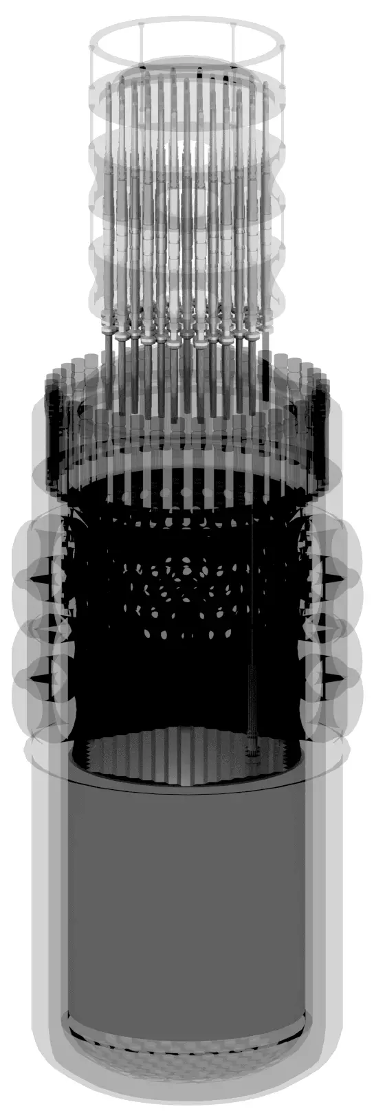
What is Temperature Profile – Nuclear Fuel – Definition

Temperature Profile – Nuclear Fuel. This example shows how to calculate the temperature distribution and temperature profile, T(r), in the fuel pellet. Thermal Engineering

Temperature Profile – Nuclear Fuel

Nuclear Fuel - Temperatures

See also: Heat Generation in Nuclear Reactors

See also: Cladding Surface Temperature

Most of PWRs use the uranium fuel, which is in the form of uranium dioxide. Uranium dioxide is a black semiconducting solid with very low thermal conductivity. On the other hand the uranium dioxide has very high melting point and has well known behavior. The UO2 is pressed into cylindrical pellets, these pellets are then sintered into the solid.

These cylindrical pellets are then loaded and encapsulated within a fuel rod (or fuel pin), which is made of zirconium alloys due to its very low absorption cross-section (unlike the stainless steel). The surface of the tube, which covers the pellets, is called fuel cladding.

See also: Thermal Conduction of Uranium Dioxide

Thermal and mechanical behavior of fuel pellets and fuel rods constitute one of three key core design disciplines. Nuclear fuel is operated under very inhospitable conditions (thermal, radiation, mechanical) and must withstand more than normal conditions operation. For example temperatures in the centre of fuel pellets reach more than 1000°C (1832°F) accompanied by fission-gas releases. Therefore detailed knowledge of temperature distribution within a single fuel rod is essential for safe operation of nuclear fuel. In this section we will study heat conduction equation in cylindrical coordinates using Dirichlet boundary condition with given surface temperature (i.e. using Dirichlet boundary condition). Comprehensive analysis of fuel rod temperature profile will be studied in separate section.

Temperature in the centerline of a fuel pellet

Consider the fuel pellet of radius rU = 0.40 cm, in which there is uniform and constant heat generation per unit volume, qV [W/m3]. Instead of volumetric heat rate qV [W/m3], engineers often use the linear heat rate, qL [W/m], which represents the heat rate of one meter of fuel rod. The linear heat rate can be calculated from the volumetric heat rate by:

linear heat rate vs volumetric heat rate

The centreline is taken as the origin for r-coordinate. Due to symmetry in z-direction and in azimuthal direction, we can separate of variables and simplify this problem to one-dimensional problem. Thus, we will solve for the temperature as function of radius, T(r), only. For constant thermal conductivity, k, the appropriate form of the cylindrical heat equation, is:

heat equation - cylindrical - 2

The general solution of this equation is:

heat equation - cylindrical - general solution

where C1 and C2 are the constants of integration.

Thermal conduction - fuel pelletCalculate the temperature distribution, T(r), in this fuel pellet, if:

  • the temperatures at the surface of the fuel pellet is TU = 420°C
  • the fuel pellet radius rU = 4 mm.
  • the averaged material’s conductivity is k = 2.8 W/m.K (corresponds to uranium dioxide at 1000°C)
  • the linear heat rate is qL = 300 W/cm and thus the volumetric heat rate is qV = 597 x 106 W/m3

In this case, the surface is maintained at given temperatures TU. This corresponds to the Dirichlet boundary condition. Moreover, this problem is thermally symmetric and therefore we may use also thermal symmetry boundary condition. The constants may be evaluated using substitution into the general solution and are of the form:

heat equation - cylindrical - boundary conditions

The resulting temperature distribution and the centerline (r = 0) temperature (maximum) in this cylindrical fuel pellet at these specific boundary conditions will be:

heat equation - cylindrical - solution

The radial heat flux at any radius, qr [W.m-1], in the cylinder may, of course, be determined by using the temperature distribution and with the Fourier’s law. Note that, with heat generation the heat flux is no longer independent of r.

The following figure shows the temperature distribution in the fuel pellet at various power levels.

Temperature distribution - nuclear fuel

______

The temperature in an operating reactor varies from point to point within the system. As a consequence, there is always one fuel rod and one local volume, that are hotter than all the rest. In order to limit these hot places the peak power limits must be introduced. The peak power limits are associated with a boiling crisis and with the conditions which could cause fuel pellet melt. However, metallurgical considerations place an upper limits on the temperature of the fuel cladding and the fuel pellet. Above these temperatures there is a danger that the fuel may be damaged. One of the major objectives in the design of a nuclear reactors is to provide for the removal of the heat produced at the desired power level, while assuring that the maximum fuel temperature and the maximum cladding temperature are always below these predetermined values.

See also: Cladding Surface Temperature

 
References:
Heat Transfer:
  1. Fundamentals of Heat and Mass Transfer, 7th Edition. Theodore L. Bergman, Adrienne S. Lavine, Frank P. Incropera. John Wiley & Sons, Incorporated, 2011. ISBN: 9781118137253.
  2. Heat and Mass Transfer. Yunus A. Cengel. McGraw-Hill Education, 2011. ISBN: 9780071077866.
  3. U.S. Department of Energy, Thermodynamics, Heat Transfer and Fluid Flow. DOE Fundamentals Handbook, Volume 2 of 3. May 2016.

Nuclear and Reactor Physics:

  1. J. R. Lamarsh, Introduction to Nuclear Reactor Theory, 2nd ed., Addison-Wesley, Reading, MA (1983).
  2. J. R. Lamarsh, A. J. Baratta, Introduction to Nuclear Engineering, 3d ed., Prentice-Hall, 2001, ISBN: 0-201-82498-1.
  3. W. M. Stacey, Nuclear Reactor Physics, John Wiley & Sons, 2001, ISBN: 0- 471-39127-1.
  4. Glasstone, Sesonske. Nuclear Reactor Engineering: Reactor Systems Engineering, Springer; 4th edition, 1994, ISBN: 978-0412985317
  5. W.S.C. Williams. Nuclear and Particle Physics. Clarendon Press; 1 edition, 1991, ISBN: 978-0198520467
  6. G.R.Keepin. Physics of Nuclear Kinetics. Addison-Wesley Pub. Co; 1st edition, 1965
  7. Robert Reed Burn, Introduction to Nuclear Reactor Operation, 1988.
  8. U.S. Department of Energy, Nuclear Physics and Reactor Theory. DOE Fundamentals Handbook, Volume 1 and 2. January 1993.
  9. Paul Reuss, Neutron Physics. EDP Sciences, 2008. ISBN: 978-2759800414.

Advanced Reactor Physics:

  1. K. O. Ott, W. A. Bezella, Introductory Nuclear Reactor Statics, American Nuclear Society, Revised edition (1989), 1989, ISBN: 0-894-48033-2.
  2. K. O. Ott, R. J. Neuhold, Introductory Nuclear Reactor Dynamics, American Nuclear Society, 1985, ISBN: 0-894-48029-4.
  3. D. L. Hetrick, Dynamics of Nuclear Reactors, American Nuclear Society, 1993, ISBN: 0-894-48453-2.
  4. E. E. Lewis, W. F. Miller, Computational Methods of Neutron Transport, American Nuclear Society, 1993, ISBN: 0-894-48452-4.

See also:

Heat Generation

We hope, this article, Temperature Profile – Nuclear Fuel, helps you. If so, give us a like in the sidebar. Main purpose of this website is to help the public to learn some interesting and important information about thermal engineering.

What is Thermal Energy Storage – Definition

Thermal energy storage forms a key component of a power plant for improvement of its dispatchability. Thermal energy storage (TES) is achieved with widely differing technologies. Thermal Engineering

Thermal Energy Storage

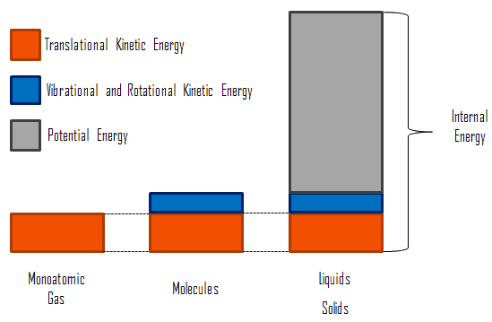
Microscopic Energy - Internal EnergyIn thermodynamics, internal energy (also called the thermal energy) is defined as the energy associated with microscopic forms of energy. It is an extensive quantity, it depends on the size of the system, or on the amount of substance it contains. The SI unit of internal energy is the joule (J). It is the energy contained within the system, excluding the kinetic energy of motion of the system as a whole and the potential energy of the system. Microscopic forms of energy include those due to the rotation, vibration, translation, and interactions among the molecules of a substance. None of these forms of energy can be measured or evaluated directly, but techniques have been developed to evaluate the change in the total sum of all these microscopic forms of energy.

In addition, energy is can be stored in the chemical bonds between the atoms that make up the molecules. This energy storage on the atomic level includes energy associated with electron orbital states, nuclear spin, and binding forces in the nucleus.

PS10 Solar Power Plant in Spain. Source: wikipedia.org License: CC BY 2.0

Thermal energy can be also very effectively stored. Nowadays, situation on energy markets is different. The increasing on the prices of the conventional energy sources and the environmental awareness have leaded to increase the use of renewable energies and the energy efficiency. Thermal energy storage forms a key component of a power plant for improvement of its dispatchability, especially for concentrating solar power plants (CSP). Thermal energy storage (TES) is achieved with widely differing technologies. There are three methods used and still being investigated in order to store thermal energy.

Sensible Heat Storage (SHS)

The most direct way is the storage of sensible heat. Sensible heat storage is based on raising the temperature of a liquid or solid to store heat and releasing it with the decrease of temperature when it is required. The volumes needed to store energy in the scale that world needs are extremely large. Materials used in sensible heat storage must have high heat capacity and also high boiling or melting point. Although this method of heat storage is currently less efficient for heat storage, it is least complicated compared with latent or chemical heat and it is inexpensive.

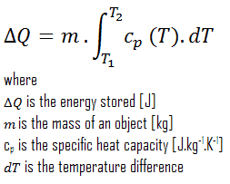
From thermodynamics point of view, the storage of sensible heat is based on the increase of enthalpy of the material in the store, either a liquid or a solid in most cases. The sensible effect is a change in temperature. Heat stored can be obtained by the equation:

sensible heat storage - equation

Heat Capacity

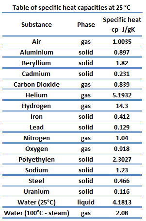
Table of specific heat capacitiesDifferent substances are affected to different magnitudes by the addition of heat. When a given amount of heat is added to different substances, their temperatures increase by different amounts. This proportionality constant between the heat Q that the object absorbs or loses and the resulting temperature change T of the object is known as the heat capacity C of an object.

C = Q / ΔT

Heat capacity is an extensive property of matter, meaning it is proportional to the size of the system. Heat capacity C has the unit of energy per degree or energy per kelvin. When expressing the same phenomenon as an intensive property, the heat capacity is divided by the amount of substance, mass, or volume, thus the quantity is independent of the size or extent of the sample.

Latent Heat Storage (LHS)

A common approach to thermal energy storage is to use materials known as phase change materials (PCMs).  These materials store heat when they undergo a phase change, for example, from solid to liquid, from liquid to gas or from solid to solid (change of one crystalline form into another without a physical phase change).

The phase change “solid-to-liquid” is the most used, but also solid-to-solid change is of interest. These materials can be used as an effective way of storing thermal energy (solar energy, off-peak electricity, industrial waste heat).  In comparison to sensible heat storage systems, the latent heat storage  has the advantages of high storage density (due to high latent heat of fusion) and the isothermal nature of the storage process. The heat of fusion or the heat of evaporation is much greater than the specific heat capacity. The comparison between latent heat storage and sensible heat storage shows that in latent heat storage storage densities are typically 5 to 10 times higher.

In general, latent heat effects associated with the phase change are significant. Latent heat, known also as the enthalpy of vaporization (liquid-to-vapor phase change) or enthalpy of fusion (solid-to-liquid phase change), is the amount of heat added to or removed from a substance to produce a change in phase. This energy breaks down the intermolecular attractive forces, and also must provide the energy necessary to expand the substance (the pΔV work). When latent heat is added, no temperature change occurs.

Phase Change Material

Phase Change Materials (PCM) are latent heat storage materials. It is possible to find materials with a latent heat of fusion and melting temperature inside the desired range. The PCM to be used in the design of thermal storage systems should accomplish desirable thermophysical, kinetics and chemical properties.

Thermo-physical Properties

  • Suitable phase-transition temperature for the specific application.
  • High latent heat of phase transition in order to occupy the minimum possible volume. .
  • Melting temperature in the desired operating temperature range.
  • High specific heat to provide for additional significant sensible heat storage.
  • High thermal conductivity in order to minimize temperature gradient and to assist the charging and discharging of energy of the storage systems.
  • Small volume changes on phase transformation and small vapor pressure at operating temperatures to reduce the containment problem.

Kinetic Properties

  • High nucleation rate to avoid supercooling of the liquid phase.
  • High rate of crystal growth, so that the system can meet demands of heat recovery from the storage system.

Chemical Properties

  • Non-toxic, non-flammable, and non-explosive materials for safety reasons.
  • Long-term chemical stability and complete reversible melt/freeze cycle.
  • No degradation after a large number of freeze / melt cycles.
  • Low corrosivity

Finally, the material must be abundant, available and cheap to help into the feasibility of the use of the storage system.

There are a large number of PCMs, they can be divided into three groups:

  • Organic PCMs
  • Inorganic PCMs
  • Eutectic PCMs

As an example, thermal energy storage can be used in concentrating solar power stations (CSP), in which the principal advantage is the ability to efficiently store energy, allowing the dispatching of electricity over up to a 24-hour period. In a CSP plant that includes storage, the solar energy is first used to heat the molten salt or synthetic oil to store thermal energy at high temperature in insulated tanks. Later hot molten salt is used for steam production to generate electricity by steam turbo generator as per requirement. The use of both latent heat and sensible heat in concentrating solar power stations are possible with high temperature solar thermal input. Various eutectic mixtures of metals, such as Aluminium and Silicon (AlSi12) offer a high melting point (577°C) suited to efficient steam generation, while high alumina cement-based materials offer good thermal storage capabilities.

Thermo-chemical Storage

One of three possible approaches to thermal energy storage is to use reversible thermo-chemical reactions. The most important advantage of the thermo-chemical storage method is that the enthalpy of reaction is considerably larger than the specific heat or the heat of fusion. Therefore the storage density is much better. In chemical reactions, energy is stored in the chemical bonds between the atoms that make up the molecules. Energy storage on the atomic level includes energy associated with electron orbital states. Whether a chemical reaction absorbs or releases energy, there is no overall change in the amount of energy during the reaction. That’s because of the law of conservation of energy, which states that:

Energy cannot be created or destroyed. Energy may change form during a chemical reaction.

One example of an experimental storage system based on chemical reaction energy is the salt hydrate technology. The system is especially advantageous for seasonal thermal energy storage. The system uses the reaction energy created when salts are hydrated or dehydrated. It works by storing heat in a container containing 50% sodium hydroxide (NaOH) solution. Heat (e.g. from using a solar collector) is stored by evaporating the water in an endothermic reaction. When water is added again, heat is released in an exothermic reaction at 50 °C. Current systems operate at 60% efficiency.

 
References:
Heat Transfer:
  1. Fundamentals of Heat and Mass Transfer, 7th Edition. Theodore L. Bergman, Adrienne S. Lavine, Frank P. Incropera. John Wiley & Sons, Incorporated, 2011. ISBN: 9781118137253.
  2. Heat and Mass Transfer. Yunus A. Cengel. McGraw-Hill Education, 2011. ISBN: 9780071077866.
  3. U.S. Department of Energy, Thermodynamics, Heat Transfer and Fluid Flow. DOE Fundamentals Handbook, Volume 2 of 3. May 2016.

Nuclear and Reactor Physics:

  1. J. R. Lamarsh, Introduction to Nuclear Reactor Theory, 2nd ed., Addison-Wesley, Reading, MA (1983).
  2. J. R. Lamarsh, A. J. Baratta, Introduction to Nuclear Engineering, 3d ed., Prentice-Hall, 2001, ISBN: 0-201-82498-1.
  3. W. M. Stacey, Nuclear Reactor Physics, John Wiley & Sons, 2001, ISBN: 0- 471-39127-1.
  4. Glasstone, Sesonske. Nuclear Reactor Engineering: Reactor Systems Engineering, Springer; 4th edition, 1994, ISBN: 978-0412985317
  5. W.S.C. Williams. Nuclear and Particle Physics. Clarendon Press; 1 edition, 1991, ISBN: 978-0198520467
  6. G.R.Keepin. Physics of Nuclear Kinetics. Addison-Wesley Pub. Co; 1st edition, 1965
  7. Robert Reed Burn, Introduction to Nuclear Reactor Operation, 1988.
  8. U.S. Department of Energy, Nuclear Physics and Reactor Theory. DOE Fundamentals Handbook, Volume 1 and 2. January 1993.
  9. Paul Reuss, Neutron Physics. EDP Sciences, 2008. ISBN: 978-2759800414.

Advanced Reactor Physics:

  1. K. O. Ott, W. A. Bezella, Introductory Nuclear Reactor Statics, American Nuclear Society, Revised edition (1989), 1989, ISBN: 0-894-48033-2.
  2. K. O. Ott, R. J. Neuhold, Introductory Nuclear Reactor Dynamics, American Nuclear Society, 1985, ISBN: 0-894-48029-4.
  3. D. L. Hetrick, Dynamics of Nuclear Reactors, American Nuclear Society, 1993, ISBN: 0-894-48453-2.
  4. E. E. Lewis, W. F. Miller, Computational Methods of Neutron Transport, American Nuclear Society, 1993, ISBN: 0-894-48452-4.

See also:

Heat Generation

We hope, this article, Thermal Energy Storage, helps you. If so, give us a like in the sidebar. Main purpose of this website is to help the public to learn some interesting and important information about thermal engineering.
What is Heat Absorption – Definition

Heat Absorption. Thermal energy can be also very effectively absorbed and stored. There are three methods used and still being investigated in order to store thermal energy. Thermal Engineering

Heat Absorption

Microscopic Energy - Internal EnergyIn thermodynamics, internal energy (also called the thermal energy) is defined as the energy associated with microscopic forms of energy. It is an extensive quantity, it depends on the size of the system, or on the amount of substance it contains. The SI unit of internal energy is the joule (J). It is the energy contained within the system, excluding the kinetic energy of motion of the system as a whole and the potential energy of the system. Microscopic forms of energy include those due to the rotation, vibration, translation, and interactions among the molecules of a substance. None of these forms of energy can be measured or evaluated directly, but techniques have been developed to evaluate the change in the total sum of all these microscopic forms of energy.

Heat Absorption

In addition, energy is can be stored in the chemical bonds between the atoms that make up the molecules. This energy storage on the atomic level includes energy associated with electron orbital states, nuclear spin, and binding forces in the nucleus.

PS10 Solar Power Plant in Spain. Source: wikipedia.org License: CC BY 2.0

Thermal energy can be also very effectively absorbed and stored. Nowadays, situation on energy markets is different. The increasing on the prices of the conventional energy sources and the environmental awareness have leaded to increase the use of renewable energies and the energy efficiency. Thermal energy storage forms a key component of a power plant for improvement of its dispatchability, especially for concentrating solar power plants (CSP). Thermal energy storage (TES) is achieved with widely differing technologies. There are three methods used and still being investigated in order to store thermal energy.

  • Sensible Heat Storage (SHS)
  • Latent Heat Storage (LHS)
  • Thermo-chemical Storage

Absorption in Sensible Heat

The most direct way is the storage of sensible heat. Sensible heat storage is based on raising the temperature of a liquid or solid to store heat and releasing it with the decrease of temperature when it is required. The volumes needed to store energy in the scale that world needs are extremely large. Materials used in sensible heat storage must have high heat capacity and also high boiling or melting point. Although this method of heat storage is currently less efficient for heat storage, it is least complicated compared with latent or chemical heat and it is inexpensive.

From thermodynamics point of view, the storage of sensible heat is based on the increase of enthalpy of the material in the store, either a liquid or a solid in most cases. The sensible effect is a change in temperature. Heat stored can be obtained by the equation:

sensible heat storage - equation

Absorption in Latent Heat

A common approach to thermal energy storage is to use materials known as phase change materials (PCMs).  These materials store heat when they undergo a phase change, for example, from solid to liquid, from liquid to gas or from solid to solid (change of one crystalline form into another without a physical phase change).

The phase change “solid-to-liquid” is the most used, but also solid-to-solid change is of interest. These materials can be used as an effective way of storing thermal energy (solar energy, off-peak electricity, industrial waste heat).  In comparison to sensible heat storage systems, the latent heat storage  has the advantages of high storage density (due to high latent heat of fusion) and the isothermal nature of the storage process. The heat of fusion or the heat of evaporation is much greater than the specific heat capacity. The comparison between latent heat storage and sensible heat storage shows that in latent heat storage storage densities are typically 5 to 10 times higher.

In general, latent heat effects associated with the phase change are significant. Latent heat, known also as the enthalpy of vaporization (liquid-to-vapor phase change) or enthalpy of fusion (solid-to-liquid phase change), is the amount of heat added to or removed from a substance to produce a change in phase. This energy breaks down the intermolecular attractive forces, and also must provide the energy necessary to expand the substance (the pΔV work). When latent heat is added, no temperature change occurs.

Absorption in Chemical Energy

One of three possible approaches to thermal energy storage is to use reversible thermo-chemical reactions. The most important advantage of the thermo-chemical storage method is that the enthalpy of reaction is considerably larger than the specific heat or the heat of fusion. Therefore the storage density is much better. In chemical reactions, energy is stored in the chemical bonds between the atoms that make up the molecules. Energy storage on the atomic level includes energy associated with electron orbital states. Whether a chemical reaction absorbs or releases energy, there is no overall change in the amount of energy during the reaction. That’s because of the law of conservation of energy, which states that:

Energy cannot be created or destroyed. Energy may change form during a chemical reaction.

One example of an experimental storage system based on chemical reaction energy is the salt hydrate technology. The system is especially advantageous for seasonal thermal energy storage. The system uses the reaction energy created when salts are hydrated or dehydrated. It works by storing heat in a container containing 50% sodium hydroxide (NaOH) solution. Heat (e.g. from using a solar collector) is stored by evaporating the water in an endothermic reaction. When water is added again, heat is released in an exothermic reaction at 50 °C. Current systems operate at 60% efficiency.

Radiant Heat Absorption

emissivity of various materialIn preceding chapters, we have discussed convection and conduction, which require the presence of matter as a medium to carry the heat from the hotter to the colder region. But a third type of heat transfer, radiation heat transfer, occurs without any medium at all. In general, the radiation heat transferfrom one surface to another is the radiation leaving the first surface for the other minus that arriving from the second surface. Radiation heat transfer is mediated by electromagnetic radiation, known as thermal radiation, that arises due to the temperature of a body.
Another important radiation property of a surface is its absorptivity, α, which is the fraction of the radiation energy incident on a surface that is absorbed by the surface. Like emissivity, value of absorptivity is in the range 0 < α < 1.

From its definition, a blackbody, which is an idealized physical body, absorbs all incident electromagnetic radiation, regardless of frequency or angle of incidence. That is, a blackbody is a perfect absorber. Since for real objects the absorptivity is less than unity, a real object can not absorb all incident light. The incomplete absorption can be due to some of the incident light being transmitted through the body or to some of it being reflected at the surface of the body.

In general, the absorptivity and the emissivity are interconnected by the Kirchhoff’s Law of thermal radiation, which states:

For an arbitrary body emitting and absorbing thermal radiation in thermodynamic equilibrium, the emissivity is equal to the absorptivity.

emissivity ε = absorptivity α

Note that visible radiation occupies a very narrow band of the spectrum from 400 to 760 nm, we cannot make any judgments about the blackness of a surface on the basis of visual observations. For example, consider white paper that reflects visible light and thus appear white. On the other hand it is essentially black for infrared radiation (absorptivity α = 0.94) since they strongly absorb long-wavelength radiation.

 
References:
Heat Transfer:
  1. Fundamentals of Heat and Mass Transfer, 7th Edition. Theodore L. Bergman, Adrienne S. Lavine, Frank P. Incropera. John Wiley & Sons, Incorporated, 2011. ISBN: 9781118137253.
  2. Heat and Mass Transfer. Yunus A. Cengel. McGraw-Hill Education, 2011. ISBN: 9780071077866.
  3. U.S. Department of Energy, Thermodynamics, Heat Transfer and Fluid Flow. DOE Fundamentals Handbook, Volume 2 of 3. May 2016.

Nuclear and Reactor Physics:

  1. J. R. Lamarsh, Introduction to Nuclear Reactor Theory, 2nd ed., Addison-Wesley, Reading, MA (1983).
  2. J. R. Lamarsh, A. J. Baratta, Introduction to Nuclear Engineering, 3d ed., Prentice-Hall, 2001, ISBN: 0-201-82498-1.
  3. W. M. Stacey, Nuclear Reactor Physics, John Wiley & Sons, 2001, ISBN: 0- 471-39127-1.
  4. Glasstone, Sesonske. Nuclear Reactor Engineering: Reactor Systems Engineering, Springer; 4th edition, 1994, ISBN: 978-0412985317
  5. W.S.C. Williams. Nuclear and Particle Physics. Clarendon Press; 1 edition, 1991, ISBN: 978-0198520467
  6. G.R.Keepin. Physics of Nuclear Kinetics. Addison-Wesley Pub. Co; 1st edition, 1965
  7. Robert Reed Burn, Introduction to Nuclear Reactor Operation, 1988.
  8. U.S. Department of Energy, Nuclear Physics and Reactor Theory. DOE Fundamentals Handbook, Volume 1 and 2. January 1993.
  9. Paul Reuss, Neutron Physics. EDP Sciences, 2008. ISBN: 978-2759800414.

Advanced Reactor Physics:

  1. K. O. Ott, W. A. Bezella, Introductory Nuclear Reactor Statics, American Nuclear Society, Revised edition (1989), 1989, ISBN: 0-894-48033-2.
  2. K. O. Ott, R. J. Neuhold, Introductory Nuclear Reactor Dynamics, American Nuclear Society, 1985, ISBN: 0-894-48029-4.
  3. D. L. Hetrick, Dynamics of Nuclear Reactors, American Nuclear Society, 1993, ISBN: 0-894-48453-2.
  4. E. E. Lewis, W. F. Miller, Computational Methods of Neutron Transport, American Nuclear Society, 1993, ISBN: 0-894-48452-4.

See also:

Heat Generation

We hope, this article, Heat Absorption, helps you. If so, give us a like in the sidebar. Main purpose of this website is to help the public to learn some interesting and important information about thermal engineering.
What is Sensible Heat Storage – SHS – Definition

The most direct way is the storage of sensible heat. Sensible heat storage is based on raising the temperature of a liquid or solid to store heat. Thermal Engineering

Sensible Heat Storage (SHS)

The most direct way is the storage of sensible heat. Sensible heat storage is based on raising the temperature of a liquid or solid to store heat and releasing it with the decrease of temperature when it is required. The volumes needed to store energy in the scale that world needs are extremely large. Materials used in sensible heat storage must have high heat capacity and also high boiling or melting point. Although this method of heat storage is currently less efficient for heat storage, it is least complicated compared with latent or chemical heat and it is inexpensive.

From thermodynamics point of view, the storage of sensible heat is based on the increase of enthalpy of the material in the store, either a liquid or a solid in most cases. The sensible effect is a change in temperature. Heat stored can be obtained by the equation:

sensible heat storage - equation

Heat Capacity

Table of specific heat capacitiesDifferent substances are affected to different magnitudes by the addition of heat. When a given amount of heat is added to different substances, their temperatures increase by different amounts. This proportionality constant between the heat Q that the object absorbs or loses and the resulting temperature change T of the object is known as the heat capacity C of an object.

C = Q / ΔT

Heat capacity is an extensive property of matter, meaning it is proportional to the size of the system. Heat capacity C has the unit of energy per degree or energy per kelvin. When expressing the same phenomenon as an intensive property, the heat capacity is divided by the amount of substance, mass, or volume, thus the quantity is independent of the size or extent of the sample.

Thermal Energy Storage

Microscopic Energy - Internal EnergyIn thermodynamics, internal energy (also called the thermal energy) is defined as the energy associated with microscopic forms of energy. It is an extensive quantity, it depends on the size of the system, or on the amount of substance it contains. The SI unit of internal energy is the joule (J). It is the energy contained within the system, excluding the kinetic energy of motion of the system as a whole and the potential energy of the system. Microscopic forms of energy include those due to the rotation, vibration, translation, and interactions among the molecules of a substance. None of these forms of energy can be measured or evaluated directly, but techniques have been developed to evaluate the change in the total sum of all these microscopic forms of energy.

In addition, energy is can be stored in the chemical bonds between the atoms that make up the molecules. This energy storage on the atomic level includes energy associated with electron orbital states, nuclear spin, and binding forces in the nucleus.

PS10 Solar Power Plant in Spain. Source: wikipedia.org License: CC BY 2.0

Thermal energy can be also very effectively stored. Nowadays, situation on energy markets is different. The increasing on the prices of the conventional energy sources and the environmental awareness have leaded to increase the use of renewable energies and the energy efficiency. Thermal energy storage forms a key component of a power plant for improvement of its dispatchability, especially for concentrating solar power plants (CSP). Thermal energy storage (TES) is achieved with widely differing technologies. There are three methods used and still being investigated in order to store thermal energy.

  • Sensible Heat Storage (SHS)
  • Latent Heat Storage (LHS)
  • Thermo-chemical Storage
 
References:
Heat Transfer:
  1. Fundamentals of Heat and Mass Transfer, 7th Edition. Theodore L. Bergman, Adrienne S. Lavine, Frank P. Incropera. John Wiley & Sons, Incorporated, 2011. ISBN: 9781118137253.
  2. Heat and Mass Transfer. Yunus A. Cengel. McGraw-Hill Education, 2011. ISBN: 9780071077866.
  3. U.S. Department of Energy, Thermodynamics, Heat Transfer and Fluid Flow. DOE Fundamentals Handbook, Volume 2 of 3. May 2016.

Nuclear and Reactor Physics:

  1. J. R. Lamarsh, Introduction to Nuclear Reactor Theory, 2nd ed., Addison-Wesley, Reading, MA (1983).
  2. J. R. Lamarsh, A. J. Baratta, Introduction to Nuclear Engineering, 3d ed., Prentice-Hall, 2001, ISBN: 0-201-82498-1.
  3. W. M. Stacey, Nuclear Reactor Physics, John Wiley & Sons, 2001, ISBN: 0- 471-39127-1.
  4. Glasstone, Sesonske. Nuclear Reactor Engineering: Reactor Systems Engineering, Springer; 4th edition, 1994, ISBN: 978-0412985317
  5. W.S.C. Williams. Nuclear and Particle Physics. Clarendon Press; 1 edition, 1991, ISBN: 978-0198520467
  6. G.R.Keepin. Physics of Nuclear Kinetics. Addison-Wesley Pub. Co; 1st edition, 1965
  7. Robert Reed Burn, Introduction to Nuclear Reactor Operation, 1988.
  8. U.S. Department of Energy, Nuclear Physics and Reactor Theory. DOE Fundamentals Handbook, Volume 1 and 2. January 1993.
  9. Paul Reuss, Neutron Physics. EDP Sciences, 2008. ISBN: 978-2759800414.

Advanced Reactor Physics:

  1. K. O. Ott, W. A. Bezella, Introductory Nuclear Reactor Statics, American Nuclear Society, Revised edition (1989), 1989, ISBN: 0-894-48033-2.
  2. K. O. Ott, R. J. Neuhold, Introductory Nuclear Reactor Dynamics, American Nuclear Society, 1985, ISBN: 0-894-48029-4.
  3. D. L. Hetrick, Dynamics of Nuclear Reactors, American Nuclear Society, 1993, ISBN: 0-894-48453-2.
  4. E. E. Lewis, W. F. Miller, Computational Methods of Neutron Transport, American Nuclear Society, 1993, ISBN: 0-894-48452-4.

See also:

Energy Storage

We hope, this article, Sensible Heat Storage – SHS, helps you. If so, give us a like in the sidebar. Main purpose of this website is to help the public to learn some interesting and important information about thermal engineering.
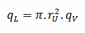
What is Latent Heat Storage – LHS – Definition

The latent heat storage has the advantages of high storage density (due to high latent heat of fusion) and the isothermal nature of the storage process. Thermal Engineering

Latent Heat Storage (LHS)

A common approach to thermal energy storage is to use materials known as phase change materials (PCMs).  These materials store heat when they undergo a phase change, for example, from solid to liquid, from liquid to gas or from solid to solid (change of one crystalline form into another without a physical phase change).

The phase change “solid-to-liquid” is the most used, but also solid-to-solid change is of interest. These materials can be used as an effective way of storing thermal energy (solar energy, off-peak electricity, industrial waste heat).  In comparison to sensible heat storage systems, the latent heat storage  has the advantages of high storage density (due to high latent heat of fusion) and the isothermal nature of the storage process. The heat of fusion or the heat of evaporation is much greater than the specific heat capacity. The comparison between latent heat storage and sensible heat storage shows that in latent heat storage storage densities are typically 5 to 10 times higher.

In general, latent heat effects associated with the phase change are significant. Latent heat, known also as the enthalpy of vaporization (liquid-to-vapor phase change) or enthalpy of fusion (solid-to-liquid phase change), is the amount of heat added to or removed from a substance to produce a change in phase. This energy breaks down the intermolecular attractive forces, and also must provide the energy necessary to expand the substance (the pΔV work). When latent heat is added, no temperature change occurs.

Phase Change Material

Phase Change Materials (PCM) are latent heat storage materials. It is possible to find materials with a latent heat of fusion and melting temperature inside the desired range. The PCM to be used in the design of thermal storage systems should accomplish desirable thermophysical, kinetics and chemical properties.

Thermo-physical Properties

  • Suitable phase-transition temperature for the specific application.
  • High latent heat of phase transition in order to occupy the minimum possible volume. .
  • Melting temperature in the desired operating temperature range.
  • High specific heat to provide for additional significant sensible heat storage.
  • High thermal conductivity in order to minimize temperature gradient and to assist the charging and discharging of energy of the storage systems.
  • Small volume changes on phase transformation and small vapor pressure at operating temperatures to reduce the containment problem.

Kinetic Properties

  • High nucleation rate to avoid supercooling of the liquid phase.
  • High rate of crystal growth, so that the system can meet demands of heat recovery from the storage system.

Chemical Properties

  • Non-toxic, non-flammable, and non-explosive materials for safety reasons.
  • Long-term chemical stability and complete reversible melt/freeze cycle.
  • No degradation after a large number of freeze / melt cycles.
  • Low corrosivity

Finally, the material must be abundant, available and cheap to help into the feasibility of the use of the storage system.

There are a large number of PCMs, they can be divided into three groups:

  • Organic PCMs
  • Inorganic PCMs
  • Eutectic PCMs

As an example, thermal energy storage can be used in concentrating solar power stations (CSP), in which the principal advantage is the ability to efficiently store energy, allowing the dispatching of electricity over up to a 24-hour period. In a CSP plant that includes storage, the solar energy is first used to heat the molten salt or synthetic oil to store thermal energy at high temperature in insulated tanks. Later hot molten salt is used for steam production to generate electricity by steam turbo generator as per requirement. The use of both latent heat and sensible heat in concentrating solar power stations are possible with high temperature solar thermal input. Various eutectic mixtures of metals, such as Aluminium and Silicon (AlSi12) offer a high melting point (577°C) suited to efficient steam generation, while high alumina cement-based materials offer good thermal storage capabilities.

Thermal Energy Storage

Microscopic Energy - Internal EnergyIn thermodynamics, internal energy (also called the thermal energy) is defined as the energy associated with microscopic forms of energy. It is an extensive quantity, it depends on the size of the system, or on the amount of substance it contains. The SI unit of internal energy is the joule (J). It is the energy contained within the system, excluding the kinetic energy of motion of the system as a whole and the potential energy of the system. Microscopic forms of energy include those due to the rotation, vibration, translation, and interactions among the molecules of a substance. None of these forms of energy can be measured or evaluated directly, but techniques have been developed to evaluate the change in the total sum of all these microscopic forms of energy.

In addition, energy is can be stored in the chemical bonds between the atoms that make up the molecules. This energy storage on the atomic level includes energy associated with electron orbital states, nuclear spin, and binding forces in the nucleus.

PS10 Solar Power Plant in Spain. Source: wikipedia.org License: CC BY 2.0

Thermal energy can be also very effectively stored. Nowadays, situation on energy markets is different. The increasing on the prices of the conventional energy sources and the environmental awareness have leaded to increase the use of renewable energies and the energy efficiency. Thermal energy storage forms a key component of a power plant for improvement of its dispatchability, especially for concentrating solar power plants (CSP). Thermal energy storage (TES) is achieved with widely differing technologies. There are three methods used and still being investigated in order to store thermal energy.

  • Sensible Heat Storage (SHS)
  • Latent Heat Storage (LHS)
  • Thermo-chemical Storage
 
References:
Heat Transfer:
  1. Fundamentals of Heat and Mass Transfer, 7th Edition. Theodore L. Bergman, Adrienne S. Lavine, Frank P. Incropera. John Wiley & Sons, Incorporated, 2011. ISBN: 9781118137253.
  2. Heat and Mass Transfer. Yunus A. Cengel. McGraw-Hill Education, 2011. ISBN: 9780071077866.
  3. U.S. Department of Energy, Thermodynamics, Heat Transfer and Fluid Flow. DOE Fundamentals Handbook, Volume 2 of 3. May 2016.

Nuclear and Reactor Physics:

  1. J. R. Lamarsh, Introduction to Nuclear Reactor Theory, 2nd ed., Addison-Wesley, Reading, MA (1983).
  2. J. R. Lamarsh, A. J. Baratta, Introduction to Nuclear Engineering, 3d ed., Prentice-Hall, 2001, ISBN: 0-201-82498-1.
  3. W. M. Stacey, Nuclear Reactor Physics, John Wiley & Sons, 2001, ISBN: 0- 471-39127-1.
  4. Glasstone, Sesonske. Nuclear Reactor Engineering: Reactor Systems Engineering, Springer; 4th edition, 1994, ISBN: 978-0412985317
  5. W.S.C. Williams. Nuclear and Particle Physics. Clarendon Press; 1 edition, 1991, ISBN: 978-0198520467
  6. G.R.Keepin. Physics of Nuclear Kinetics. Addison-Wesley Pub. Co; 1st edition, 1965
  7. Robert Reed Burn, Introduction to Nuclear Reactor Operation, 1988.
  8. U.S. Department of Energy, Nuclear Physics and Reactor Theory. DOE Fundamentals Handbook, Volume 1 and 2. January 1993.
  9. Paul Reuss, Neutron Physics. EDP Sciences, 2008. ISBN: 978-2759800414.

Advanced Reactor Physics:

  1. K. O. Ott, W. A. Bezella, Introductory Nuclear Reactor Statics, American Nuclear Society, Revised edition (1989), 1989, ISBN: 0-894-48033-2.
  2. K. O. Ott, R. J. Neuhold, Introductory Nuclear Reactor Dynamics, American Nuclear Society, 1985, ISBN: 0-894-48029-4.
  3. D. L. Hetrick, Dynamics of Nuclear Reactors, American Nuclear Society, 1993, ISBN: 0-894-48453-2.
  4. E. E. Lewis, W. F. Miller, Computational Methods of Neutron Transport, American Nuclear Society, 1993, ISBN: 0-894-48452-4.

See also:

Energy Storage

We hope, this article, Latent Heat Storage – LHS, helps you. If so, give us a like in the sidebar. Main purpose of this website is to help the public to learn some interesting and important information about thermal engineering.
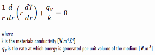
What is Phase Change Material – PCM – Definition

The Phase Change Materials, PCMs, to be used in the design of thermal storage systems should accomplish desirable thermophysical, kinetics and chemical properties. Thermal Engineering

Phase Change Material

Phase Change Materials (PCM) are latent heat storage materials. It is possible to find materials with a latent heat of fusion and melting temperature inside the desired range. The PCM to be used in the design of thermal storage systems should accomplish desirable thermophysical, kinetics and chemical properties.

Thermo-physical Properties

  • Suitable phase-transition temperature for the specific application.
  • High latent heat of phase transition in order to occupy the minimum possible volume. .
  • Melting temperature in the desired operating temperature range.
  • High specific heat to provide for additional significant sensible heat storage.
  • High thermal conductivity in order to minimize temperature gradient and to assist the charging and discharging of energy of the storage systems.
  • Small volume changes on phase transformation and small vapor pressure at operating temperatures to reduce the containment problem.

Kinetic Properties

  • High nucleation rate to avoid supercooling of the liquid phase.
  • High rate of crystal growth, so that the system can meet demands of heat recovery from the storage system.

Chemical Properties

  • Non-toxic, non-flammable, and non-explosive materials for safety reasons.
  • Long-term chemical stability and complete reversible melt/freeze cycle.
  • No degradation after a large number of freeze / melt cycles.
  • Low corrosivity

Finally, the material must be abundant, available and cheap to help into the feasibility of the use of the storage system.

There are a large number of PCMs, they can be divided into three groups:

  • Organic PCMs
  • Inorganic PCMs
  • Eutectic PCMs

As an example, thermal energy storage can be used in concentrating solar power stations (CSP), in which the principal advantage is the ability to efficiently store energy, allowing the dispatching of electricity over up to a 24-hour period. In a CSP plant that includes storage, the solar energy is first used to heat the molten salt or synthetic oil to store thermal energy at high temperature in insulated tanks. Later hot molten salt is used for steam production to generate electricity by steam turbo generator as per requirement. The use of both latent heat and sensible heat in concentrating solar power stations are possible with high temperature solar thermal input. Various eutectic mixtures of metals, such as Aluminium and Silicon (AlSi12) offer a high melting point (577°C) suited to efficient steam generation, while high alumina cement-based materials offer good thermal storage capabilities.

 
References:
Heat Transfer:
  1. Fundamentals of Heat and Mass Transfer, 7th Edition. Theodore L. Bergman, Adrienne S. Lavine, Frank P. Incropera. John Wiley & Sons, Incorporated, 2011. ISBN: 9781118137253.
  2. Heat and Mass Transfer. Yunus A. Cengel. McGraw-Hill Education, 2011. ISBN: 9780071077866.
  3. U.S. Department of Energy, Thermodynamics, Heat Transfer and Fluid Flow. DOE Fundamentals Handbook, Volume 2 of 3. May 2016.

Nuclear and Reactor Physics:

  1. J. R. Lamarsh, Introduction to Nuclear Reactor Theory, 2nd ed., Addison-Wesley, Reading, MA (1983).
  2. J. R. Lamarsh, A. J. Baratta, Introduction to Nuclear Engineering, 3d ed., Prentice-Hall, 2001, ISBN: 0-201-82498-1.
  3. W. M. Stacey, Nuclear Reactor Physics, John Wiley & Sons, 2001, ISBN: 0- 471-39127-1.
  4. Glasstone, Sesonske. Nuclear Reactor Engineering: Reactor Systems Engineering, Springer; 4th edition, 1994, ISBN: 978-0412985317
  5. W.S.C. Williams. Nuclear and Particle Physics. Clarendon Press; 1 edition, 1991, ISBN: 978-0198520467
  6. G.R.Keepin. Physics of Nuclear Kinetics. Addison-Wesley Pub. Co; 1st edition, 1965
  7. Robert Reed Burn, Introduction to Nuclear Reactor Operation, 1988.
  8. U.S. Department of Energy, Nuclear Physics and Reactor Theory. DOE Fundamentals Handbook, Volume 1 and 2. January 1993.
  9. Paul Reuss, Neutron Physics. EDP Sciences, 2008. ISBN: 978-2759800414.

Advanced Reactor Physics:

  1. K. O. Ott, W. A. Bezella, Introductory Nuclear Reactor Statics, American Nuclear Society, Revised edition (1989), 1989, ISBN: 0-894-48033-2.
  2. K. O. Ott, R. J. Neuhold, Introductory Nuclear Reactor Dynamics, American Nuclear Society, 1985, ISBN: 0-894-48029-4.
  3. D. L. Hetrick, Dynamics of Nuclear Reactors, American Nuclear Society, 1993, ISBN: 0-894-48453-2.
  4. E. E. Lewis, W. F. Miller, Computational Methods of Neutron Transport, American Nuclear Society, 1993, ISBN: 0-894-48452-4.

See also:

Energy Storage

We hope, this article, Phase Change Material – PCM, helps you. If so, give us a like in the sidebar. Main purpose of this website is to help the public to learn some interesting and important information about thermal engineering.