Facebook Instagram Youtube Twitter

What is Thermo-chemical Storage – Definition

The most important advantage of the thermo-chemical storage method is that the enthalpy of reaction is considerably larger than the specific heat or the heat of fusion. Thermal Engineering

Thermo-chemical Storage

One of three possible approaches to thermal energy storage is to use reversible thermo-chemical reactions. The most important advantage of the thermo-chemical storage method is that the enthalpy of reaction is considerably larger than the specific heat or the heat of fusion. Therefore the storage density is much better. In chemical reactions, energy is stored in the chemical bonds between the atoms that make up the molecules. Energy storage on the atomic level includes energy associated with electron orbital states. Whether a chemical reaction absorbs or releases energy, there is no overall change in the amount of energy during the reaction. That’s because of the law of conservation of energy, which states that:

Energy cannot be created or destroyed. Energy may change form during a chemical reaction.

One example of an experimental storage system based on chemical reaction energy is the salt hydrate technology. The system is especially advantageous for seasonal thermal energy storage. The system uses the reaction energy created when salts are hydrated or dehydrated. It works by storing heat in a container containing 50% sodium hydroxide (NaOH) solution. Heat (e.g. from using a solar collector) is stored by evaporating the water in an endothermic reaction. When water is added again, heat is released in an exothermic reaction at 50 °C. Current systems operate at 60% efficiency.

Thermal Energy Storage
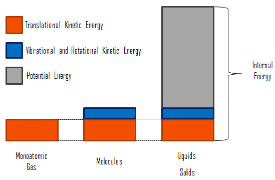
Microscopic Energy - Internal EnergyIn thermodynamics, internal energy (also called the thermal energy) is defined as the energy associated with microscopic forms of energy. It is an extensive quantity, it depends on the size of the system, or on the amount of substance it contains. The SI unit of internal energy is the joule (J). It is the energy contained within the system, excluding the kinetic energy of motion of the system as a whole and the potential energy of the system. Microscopic forms of energy include those due to the rotation, vibration, translation, and interactions among the molecules of a substance. None of these forms of energy can be measured or evaluated directly, but techniques have been developed to evaluate the change in the total sum of all these microscopic forms of energy.

In addition, energy is can be stored in the chemical bonds between the atoms that make up the molecules. This energy storage on the atomic level includes energy associated with electron orbital states, nuclear spin, and binding forces in the nucleus.

PS10 Solar Power Plant in Spain. Source: wikipedia.org License: CC BY 2.0

Thermal energy can be also very effectively stored. Nowadays, situation on energy markets is different. The increasing on the prices of the conventional energy sources and the environmental awareness have leaded to increase the use of renewable energies and the energy efficiency. Thermal energy storage forms a key component of a power plant for improvement of its dispatchability, especially for concentrating solar power plants (CSP). Thermal energy storage (TES) is achieved with widely differing technologies. There are three methods used and still being investigated in order to store thermal energy.

  • Sensible Heat Storage (SHS)
  • Latent Heat Storage (LHS)
  • Thermo-chemical Storage
 
References:
Heat Transfer:
  1. Fundamentals of Heat and Mass Transfer, 7th Edition. Theodore L. Bergman, Adrienne S. Lavine, Frank P. Incropera. John Wiley & Sons, Incorporated, 2011. ISBN: 9781118137253.
  2. Heat and Mass Transfer. Yunus A. Cengel. McGraw-Hill Education, 2011. ISBN: 9780071077866.
  3. U.S. Department of Energy, Thermodynamics, Heat Transfer and Fluid Flow. DOE Fundamentals Handbook, Volume 2 of 3. May 2016.

Nuclear and Reactor Physics:

  1. J. R. Lamarsh, Introduction to Nuclear Reactor Theory, 2nd ed., Addison-Wesley, Reading, MA (1983).
  2. J. R. Lamarsh, A. J. Baratta, Introduction to Nuclear Engineering, 3d ed., Prentice-Hall, 2001, ISBN: 0-201-82498-1.
  3. W. M. Stacey, Nuclear Reactor Physics, John Wiley & Sons, 2001, ISBN: 0- 471-39127-1.
  4. Glasstone, Sesonske. Nuclear Reactor Engineering: Reactor Systems Engineering, Springer; 4th edition, 1994, ISBN: 978-0412985317
  5. W.S.C. Williams. Nuclear and Particle Physics. Clarendon Press; 1 edition, 1991, ISBN: 978-0198520467
  6. G.R.Keepin. Physics of Nuclear Kinetics. Addison-Wesley Pub. Co; 1st edition, 1965
  7. Robert Reed Burn, Introduction to Nuclear Reactor Operation, 1988.
  8. U.S. Department of Energy, Nuclear Physics and Reactor Theory. DOE Fundamentals Handbook, Volume 1 and 2. January 1993.
  9. Paul Reuss, Neutron Physics. EDP Sciences, 2008. ISBN: 978-2759800414.

Advanced Reactor Physics:

  1. K. O. Ott, W. A. Bezella, Introductory Nuclear Reactor Statics, American Nuclear Society, Revised edition (1989), 1989, ISBN: 0-894-48033-2.
  2. K. O. Ott, R. J. Neuhold, Introductory Nuclear Reactor Dynamics, American Nuclear Society, 1985, ISBN: 0-894-48029-4.
  3. D. L. Hetrick, Dynamics of Nuclear Reactors, American Nuclear Society, 1993, ISBN: 0-894-48453-2.
  4. E. E. Lewis, W. F. Miller, Computational Methods of Neutron Transport, American Nuclear Society, 1993, ISBN: 0-894-48452-4.

See also:

Energy Storage

We hope, this article, Thermo-chemical Storage, helps you. If so, give us a like in the sidebar. Main purpose of this website is to help the public to learn some interesting and important information about thermal engineering.
What is Heat Loss – Definition

Heat losses from hotter objects occur by three mechanisms. There is no material which can completely prevent heat losses, heat losses can be only minimized. Thermal Engineering

Heat Losses

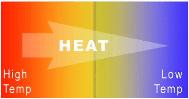
zeroth-law-of-thermodynamics-heatWhile thermal energy refers to the total energy of all the molecules within the object, heat is the amount of energy flowing from one body to another spontaneously due to their temperature difference. Heat is a form of energy, but it is energy in transit. Heat is not a property of a system. However, the transfer of energy as heat occurs at the molecular level as a result of a temperature difference. When a temperature difference does exist heat flows spontaneously from the warmer system to the colder system, never the reverse. This direction of thermodynamic processes is given by the second law of thermodynamics.

As a result, any object hotter than the surroundings must continuously lose a part of its thermal energy. This is a natural behaviour of all objects. When the flow of heat stops, they are said to be at the same temperature. They are then said to be in thermal equilibrium. Heat losses from hotter objects occur by three mechanisms (either individually or in combination):

  • Heat Conduction. Heat conduction, also called diffusion, occurs within a body or between two bodies in contact. It is the direct microscopic exchange of kinetic energy of particles through the boundary between two systems. When an object is at a different temperature from another body or its surroundings
  • Heat Convection. Heat convection depends on motion of mass from one region of space to another. Heat convection occurs when bulk flow of a fluid (gas or liquid) carries heat along with the flow of matter in the fluid.
  • Thermal Radiation. Radiation is heat transfer by electromagnetic radiation, such as sunshine, with no need for matter to be present in the space between bodies.

Heat Losses – Clothing

The purpose of clothing is similar. The insulating properties of clothing come from the insulating properties of air. Gases possess poor thermal conduction properties compared to liquids and solids, and thus makes a good insulation material if they can be trapped (e.g. in a foam-like structure). Air and other gases are generally good insulators. But the main benefit is in the absence of convection. Without clothes, our bodies in still air would heat the air in direct contact with the skin and would soon become reasonably comfortable because air is a very good insulator. It must be added, also in this case air will be flowing due to natural convection. In natural convection, air surrounding a body receives heat and by thermal expansion becomes less dense and rises. Thermal expansion of air plays a crucial role. In other words, heavier (more dense) components will fall, while lighter (less dense) components rise, leading to bulk air movement.

In the wind, the warm air surrounding our body would be replaced by cold air, thus increasing the temperature difference and the heat loss from the body. Clothes constitute a barrier to this moving air. The main benefit is in the absence of large-scale convection. Moreover, clothes are made from materials, which are generally good insulators. Many insulating materials (e.g. wool) function simply by having a large number of gas-filled pockets which significantly decrease material’s thermal conductivity. Alternation of gas pocket and solid material causes that the heat must be transferred through many interfaces causing rapid decrease in heat transfer coefficient.

Heat Losses – Thermal Insulation

expanded polystyrene - thermal insulation
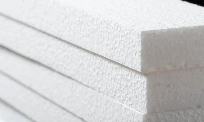
Expanded polystyrene insulation

In order to minimize heat losses in industry and also in construction of buildings, thermal insulation is widely used. The purpose of thermal insulation of is to reduce the overall heat transfer coefficient by adding of material with low thermal conductivity.  Thermal insulation in buildings is an important factor to achieving thermal comfort for its occupants. Thermal insulation reduces unwanted heat loss and also reduce unwanted heat gain. Therefore thermal insulation can decrease the energy demands of heating and cooling systems. It must be added, there is no material which can completely prevent heat losses, heat losses can be only minimized.

Similarly as for clothing, thermal insulation is based on low thermal conductivity materials and on its geometry (e.g. double-pane windows). The insulating properties of these materials come from the insulating properties of air. Many insulating materials (e.g. glass wool) function simply by having a large number of gas-filled pockets which prevent large-scale convection. Geometry of these materials plays also crucial role. For example,  increasing the width of the air layer, such as using two panes of glass separated by an air gap, will reduce the heat loss more than simply increasing the glass thickness, since the thermal conductivity of air is much less than that for glass.

Example – Heat Loss through a Wall

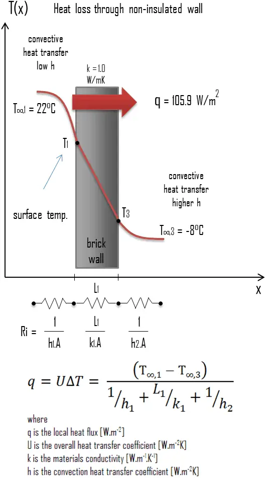
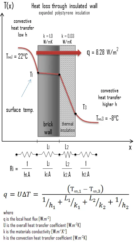
heat loss through wall - example - calculationA major source of heat loss from a house is through walls. Calculate the rate of heat flux through a wall 3 m x 10 m in area (A = 30 m2). The wall is 15 cm thick (L1) and it is made of bricks with the thermal conductivity of k1 = 1.0 W/m.K (poor thermal insulator). Assume that, the indoor and the outdoor temperatures are 22°C and -8°C, and the convection heat transfer coefficients on the inner and the outer sides are h1 = 10 W/m2K and h2 = 30 W/m2K, respectively. Note that, these convection coefficients strongly depend especially on ambient and interior conditions (wind, humidity, etc.).

  1. Calculate the heat flux (heat loss) through this non-insulated wall.
  2. Now assume thermal insulation on the outer side of this wall. Use expanded polystyrene insulation 10 cm thick (L2) with the thermal conductivity of k2 = 0.03 W/m.K and calculate the heat flux (heat loss) through this composite wall.

Solution:

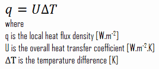
As was written, many of the heat transfer processes involve composite systems and even involve a combination of both conduction and convection. With these composite systems, it is often convenient to work with an overall heat transfer coefficient, known as a U-factor. The U-factor is defined by an expression analogous to Newton’s law of cooling:

u-factor - overall heat transfer coefficient

The overall heat transfer coefficient is related to the total thermal resistance and depends on the geometry of the problem.

  1. bare wall

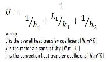
Assuming one-dimensional heat transfer through the plane wall and disregarding radiation, the overall heat transfer coefficient can be calculated as:

overall heat transfer coefficient - heat loss calculation

The overall heat transfer coefficient is then:

U = 1 / (1/10 + 0.15/1 + 1/30) = 3.53 W/m2K

The heat flux can be then calculated simply as:

q = 3.53 [W/m2K] x 30 [K] = 105.9 W/m2

The total heat loss through this wall will be:

qloss = q . A = 105.9 [W/m2] x 30 [m2] = 3177W

  1. composite wall with thermal insulation

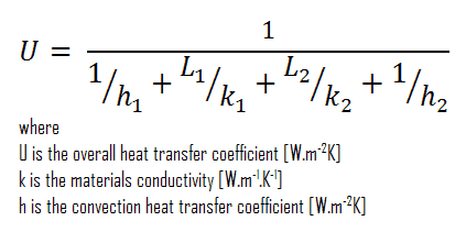
Assuming one-dimensional heat transfer through the plane composite wall, no thermal contact resistance and disregarding radiation, the overall heat transfer coefficient can be calculated as:

overall heat transfer coefficient - thermal insulation calculation

thermal insulation - expanded polystyreneThe overall heat transfer coefficient is then:

U = 1 / (1/10 + 0.15/1 + 0.1/0.03 + 1/30) = 0.276 W/m2K

The heat flux can be then calculated simply as:

q = 0.276 [W/m2K] x 30 [K] = 8.28 W/m2

The total heat loss through this wall will be:

qloss = q . A = 8.28 [W/m2] x 30 [m2] = 248 W

As can be seen, an addition of thermal insulator causes significant decrease in heat losses. It must be added, an addition of next layer of thermal insulator does not cause such high savings. This can be better seen from the thermal resistance method, which can be used to calculate the heat transfer through composite walls. The rate of steady heat transfer between two surfaces is equal to the temperature difference divided by the total thermal resistance between those two surfaces.

thermal resistance - equation

Example – Heat Loss through a Window

Example - Heat Flux - Thermal ConductionHeat loss through windows

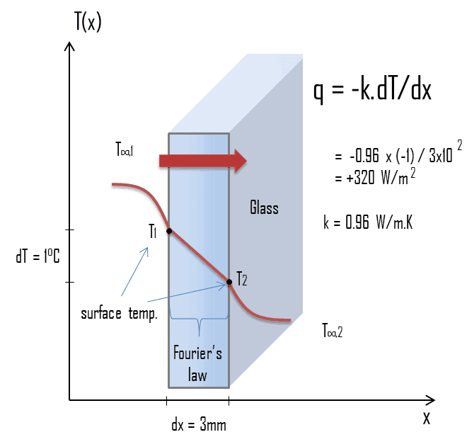
A major source of heat loss from a house is through the windows. Calculate the rate of heat flux through a glass window 1.5 m x 1.0 m in area and 3.0 mm thick, if the temperatures at the inner and outer surfaces are 14.0°C and 13.0°C, respectively. Calculate the heat flux through this window.

Solution:

At this point, we know the temperatures at the surfaces of material. These temperatures are given also by conditions inside the house and outside the house. In this case, heat flows by conduction through the glass from the higher inside temperature to the lower outside temperature. We use the heat conduction equation:

Heat loss through window - equation

We assume that the thermal conductivity of a common glass is k = 0.96 W/m.K.

The heat flux will then be:

q = 0.96 [W/m.K] x 1 [K] / 3.0 x 10-3 [m] = 320 W/m2

The total heat loss through this window will be:

qloss = q . A = 320 x 1.5 x 1.0 = 480W

It must be added, 15°C is not very warm for the living room of a house. But this temperature does not correspond to the interior temperature, but correspond to the surface temperature. Due to the finite convective heat transfer coefficient, there is always a considerable temperature drop between the interior temperature and the window surface temperature. Note that, both convection coefficients strongly depend especially on ambient and interior conditions (wind, humidity, etc.).

See also: Convective Heat Transfer Coefficient

Similarly as for clothing, thermal insulation is based on low thermal conductivity materials and on its geometry (e.g. double-pane windows). The insulating properties of these materials come from the insulating properties of air. Many insulating materials (e.g. wool) function simply by having a large number of gas-filled pockets which prevent large-scale convection. Geometry of these materials plays also crucial role. For example, increasing the width of the air layer, such as using two panes of glass separated by an air gap, will reduce the heat loss more than simply increasing the glass thickness, since the thermal conductivity of air is much less than that for glass.

 
References:
Heat Transfer:
  1. Fundamentals of Heat and Mass Transfer, 7th Edition. Theodore L. Bergman, Adrienne S. Lavine, Frank P. Incropera. John Wiley & Sons, Incorporated, 2011. ISBN: 9781118137253.
  2. Heat and Mass Transfer. Yunus A. Cengel. McGraw-Hill Education, 2011. ISBN: 9780071077866.
  3. U.S. Department of Energy, Thermodynamics, Heat Transfer and Fluid Flow. DOE Fundamentals Handbook, Volume 2 of 3. May 2016.

Nuclear and Reactor Physics:

  1. J. R. Lamarsh, Introduction to Nuclear Reactor Theory, 2nd ed., Addison-Wesley, Reading, MA (1983).
  2. J. R. Lamarsh, A. J. Baratta, Introduction to Nuclear Engineering, 3d ed., Prentice-Hall, 2001, ISBN: 0-201-82498-1.
  3. W. M. Stacey, Nuclear Reactor Physics, John Wiley & Sons, 2001, ISBN: 0- 471-39127-1.
  4. Glasstone, Sesonske. Nuclear Reactor Engineering: Reactor Systems Engineering, Springer; 4th edition, 1994, ISBN: 978-0412985317
  5. W.S.C. Williams. Nuclear and Particle Physics. Clarendon Press; 1 edition, 1991, ISBN: 978-0198520467
  6. G.R.Keepin. Physics of Nuclear Kinetics. Addison-Wesley Pub. Co; 1st edition, 1965
  7. Robert Reed Burn, Introduction to Nuclear Reactor Operation, 1988.
  8. U.S. Department of Energy, Nuclear Physics and Reactor Theory. DOE Fundamentals Handbook, Volume 1 and 2. January 1993.
  9. Paul Reuss, Neutron Physics. EDP Sciences, 2008. ISBN: 978-2759800414.

Advanced Reactor Physics:

  1. K. O. Ott, W. A. Bezella, Introductory Nuclear Reactor Statics, American Nuclear Society, Revised edition (1989), 1989, ISBN: 0-894-48033-2.
  2. K. O. Ott, R. J. Neuhold, Introductory Nuclear Reactor Dynamics, American Nuclear Society, 1985, ISBN: 0-894-48029-4.
  3. D. L. Hetrick, Dynamics of Nuclear Reactors, American Nuclear Society, 1993, ISBN: 0-894-48453-2.
  4. E. E. Lewis, W. F. Miller, Computational Methods of Neutron Transport, American Nuclear Society, 1993, ISBN: 0-894-48452-4.

See also:

Heat Transfer

We hope, this article, Heat Loss, helps you. If so, give us a like in the sidebar. Main purpose of this website is to help the public to learn some interesting and important information about thermal engineering.
What is Heat Loss through Clothing – Definition

Heat Losses through Clothing. The purpose of clothing is similar.. The insulating properties of clothing come from the insulating properties of air. Thermal Engineering

Heat Losses – Clothing

The purpose of clothing is similar. The insulating properties of clothing come from the insulating properties of air. Gases possess poor thermal conduction properties compared to liquids and solids, and thus makes a good insulation material if they can be trapped (e.g. in a foam-like structure). Air and other gases are generally good insulators. But the main benefit is in the absence of convection. Without clothes, our bodies in still air would heat the air in direct contact with the skin and would soon become reasonably comfortable because air is a very good insulator. It must be added, also in this case air will be flowing due to natural convection. In natural convection, air surrounding a body receives heat and by thermal expansion becomes less dense and rises. Thermal expansion of air plays a crucial role. In other words, heavier (more dense) components will fall, while lighter (less dense) components rise, leading to bulk air movement.

In the wind, the warm air surrounding our body would be replaced by cold air, thus increasing the temperature difference and the heat loss from the body. Clothes constitute a barrier to this moving air. The main benefit is in the absence of large-scale convection. Moreover, clothes are made from materials, which are generally good insulators. Many insulating materials (e.g. wool) function simply by having a large number of gas-filled pockets which significantly decrease material’s thermal conductivity. Alternation of gas pocket and solid material causes that the heat must be transferred through many interfaces causing rapid decrease in heat transfer coefficient.

Heat Losses

zeroth-law-of-thermodynamics-heatWhile thermal energy refers to the total energy of all the molecules within the object, heat is the amount of energy flowing from one body to another spontaneously due to their temperature difference. Heat is a form of energy, but it is energy in transit. Heat is not a property of a system. However, the transfer of energy as heat occurs at the molecular level as a result of a temperature difference. When a temperature difference does exist heat flows spontaneously from the warmer system to the colder system, never the reverse. This direction of thermodynamic processes is given by the second law of thermodynamics.

As a result, any object hotter than the surroundings must continuously lose a part of its thermal energy. This is a natural behaviour of all objects. When the flow of heat stops, they are said to be at the same temperature. They are then said to be in thermal equilibrium. Heat losses from hotter objects occur by three mechanisms (either individually or in combination):

  • Heat Conduction. Heat conduction, also called diffusion, occurs within a body or between two bodies in contact. It is the direct microscopic exchange of kinetic energy of particles through the boundary between two systems. When an object is at a different temperature from another body or its surroundings
  • Heat Convection. Heat convection depends on motion of mass from one region of space to another. Heat convection occurs when bulk flow of a fluid (gas or liquid) carries heat along with the flow of matter in the fluid.
  • Thermal Radiation. Radiation is heat transfer by electromagnetic radiation, such as sunshine, with no need for matter to be present in the space between bodies.
 
References:
Heat Transfer:
  1. Fundamentals of Heat and Mass Transfer, 7th Edition. Theodore L. Bergman, Adrienne S. Lavine, Frank P. Incropera. John Wiley & Sons, Incorporated, 2011. ISBN: 9781118137253.
  2. Heat and Mass Transfer. Yunus A. Cengel. McGraw-Hill Education, 2011. ISBN: 9780071077866.
  3. U.S. Department of Energy, Thermodynamics, Heat Transfer and Fluid Flow. DOE Fundamentals Handbook, Volume 2 of 3. May 2016.

Nuclear and Reactor Physics:

  1. J. R. Lamarsh, Introduction to Nuclear Reactor Theory, 2nd ed., Addison-Wesley, Reading, MA (1983).
  2. J. R. Lamarsh, A. J. Baratta, Introduction to Nuclear Engineering, 3d ed., Prentice-Hall, 2001, ISBN: 0-201-82498-1.
  3. W. M. Stacey, Nuclear Reactor Physics, John Wiley & Sons, 2001, ISBN: 0- 471-39127-1.
  4. Glasstone, Sesonske. Nuclear Reactor Engineering: Reactor Systems Engineering, Springer; 4th edition, 1994, ISBN: 978-0412985317
  5. W.S.C. Williams. Nuclear and Particle Physics. Clarendon Press; 1 edition, 1991, ISBN: 978-0198520467
  6. G.R.Keepin. Physics of Nuclear Kinetics. Addison-Wesley Pub. Co; 1st edition, 1965
  7. Robert Reed Burn, Introduction to Nuclear Reactor Operation, 1988.
  8. U.S. Department of Energy, Nuclear Physics and Reactor Theory. DOE Fundamentals Handbook, Volume 1 and 2. January 1993.
  9. Paul Reuss, Neutron Physics. EDP Sciences, 2008. ISBN: 978-2759800414.

Advanced Reactor Physics:

  1. K. O. Ott, W. A. Bezella, Introductory Nuclear Reactor Statics, American Nuclear Society, Revised edition (1989), 1989, ISBN: 0-894-48033-2.
  2. K. O. Ott, R. J. Neuhold, Introductory Nuclear Reactor Dynamics, American Nuclear Society, 1985, ISBN: 0-894-48029-4.
  3. D. L. Hetrick, Dynamics of Nuclear Reactors, American Nuclear Society, 1993, ISBN: 0-894-48453-2.
  4. E. E. Lewis, W. F. Miller, Computational Methods of Neutron Transport, American Nuclear Society, 1993, ISBN: 0-894-48452-4.

See also:

Heat Losses

We hope, this article, Heat Loss through Clothing, helps you. If so, give us a like in the sidebar. Main purpose of this website is to help the public to learn some interesting and important information about thermal engineering.
What is Heat Loss through a Wall – Definition

Heat Loss through a Wall. Calculate the rate of heat flux through a wall 3 m x 10 m in area (A = 30 m2). The wall is 15 cm thick (L1) and it is made of bricks with the thermal conductivity of k1 = 1.0 W/m.K

Example – Heat Loss through a Wall

heat loss through wall - example - calculationA major source of heat loss from a house is through walls. Calculate the rate of heat flux through a wall 3 m x 10 m in area (A = 30 m2). The wall is 15 cm thick (L1) and it is made of bricks with the thermal conductivity of k1 = 1.0 W/m.K (poor thermal insulator). Assume that, the indoor and the outdoor temperatures are 22°C and -8°C, and the convection heat transfer coefficients on the inner and the outer sides are h1 = 10 W/m2K and h2 = 30 W/m2K, respectively. Note that, these convection coefficients strongly depend especially on ambient and interior conditions (wind, humidity, etc.).

  1. Calculate the heat flux (heat loss) through this non-insulated wall.
  2. Now assume thermal insulation on the outer side of this wall. Use expanded polystyrene insulation 10 cm thick (L2) with the thermal conductivity of k2 = 0.03 W/m.K and calculate the heat flux (heat loss) through this composite wall.

Solution:

As was written, many of the heat transfer processes involve composite systems and even involve a combination of both conduction and convection. With these composite systems, it is often convenient to work with an overall heat transfer coefficient, known as a U-factor. The U-factor is defined by an expression analogous to Newton’s law of cooling:

u-factor - overall heat transfer coefficient

The overall heat transfer coefficient is related to the total thermal resistance and depends on the geometry of the problem.

  1. bare wall

Assuming one-dimensional heat transfer through the plane wall and disregarding radiation, the overall heat transfer coefficient can be calculated as:

overall heat transfer coefficient - heat loss calculation

The overall heat transfer coefficient is then:

U = 1 / (1/10 + 0.15/1 + 1/30) = 3.53 W/m2K

The heat flux can be then calculated simply as:

q = 3.53 [W/m2K] x 30 [K] = 105.9 W/m2

The total heat loss through this wall will be:

qloss = q . A = 105.9 [W/m2] x 30 [m2] = 3177W

  1. composite wall with thermal insulation

Assuming one-dimensional heat transfer through the plane composite wall, no thermal contact resistance and disregarding radiation, the overall heat transfer coefficient can be calculated as:

overall heat transfer coefficient - thermal insulation calculation

thermal insulation - expanded polystyreneThe overall heat transfer coefficient is then:

U = 1 / (1/10 + 0.15/1 + 0.1/0.03 + 1/30) = 0.276 W/m2K

The heat flux can be then calculated simply as:

q = 0.276 [W/m2K] x 30 [K] = 8.28 W/m2

The total heat loss through this wall will be:

qloss = q . A = 8.28 [W/m2] x 30 [m2] = 248 W

As can be seen, an addition of thermal insulator causes significant decrease in heat losses. It must be added, an addition of next layer of thermal insulator does not cause such high savings. This can be better seen from the thermal resistance method, which can be used to calculate the heat transfer through composite walls. The rate of steady heat transfer between two surfaces is equal to the temperature difference divided by the total thermal resistance between those two surfaces.

thermal resistance - equation

Heat Losses – Thermal Insulation

expanded polystyrene - thermal insulation
Expanded polystyrene insulation

In order to minimize heat losses in industry and also in construction of buildings, thermal insulation is widely used. The purpose of thermal insulation of is to reduce the overall heat transfer coefficient by adding of material with low thermal conductivity.  Thermal insulation in buildings is an important factor to achieving thermal comfort for its occupants. Thermal insulation reduces unwanted heat loss and also reduce unwanted heat gain. Therefore thermal insulation can decrease the energy demands of heating and cooling systems. It must be added, there is no material which can completely prevent heat losses, heat losses can be only minimized.

Similarly as for clothing, thermal insulation is based on low thermal conductivity materials and on its geometry (e.g. double-pane windows). The insulating properties of these materials come from the insulating properties of air. Many insulating materials (e.g. glass wool) function simply by having a large number of gas-filled pockets which prevent large-scale convection. Geometry of these materials plays also crucial role. For example,  increasing the width of the air layer, such as using two panes of glass separated by an air gap, will reduce the heat loss more than simply increasing the glass thickness, since the thermal conductivity of air is much less than that for glass.

 
References:
Heat Transfer:
  1. Fundamentals of Heat and Mass Transfer, 7th Edition. Theodore L. Bergman, Adrienne S. Lavine, Frank P. Incropera. John Wiley & Sons, Incorporated, 2011. ISBN: 9781118137253.
  2. Heat and Mass Transfer. Yunus A. Cengel. McGraw-Hill Education, 2011. ISBN: 9780071077866.
  3. U.S. Department of Energy, Thermodynamics, Heat Transfer and Fluid Flow. DOE Fundamentals Handbook, Volume 2 of 3. May 2016.

Nuclear and Reactor Physics:

  1. J. R. Lamarsh, Introduction to Nuclear Reactor Theory, 2nd ed., Addison-Wesley, Reading, MA (1983).
  2. J. R. Lamarsh, A. J. Baratta, Introduction to Nuclear Engineering, 3d ed., Prentice-Hall, 2001, ISBN: 0-201-82498-1.
  3. W. M. Stacey, Nuclear Reactor Physics, John Wiley & Sons, 2001, ISBN: 0- 471-39127-1.
  4. Glasstone, Sesonske. Nuclear Reactor Engineering: Reactor Systems Engineering, Springer; 4th edition, 1994, ISBN: 978-0412985317
  5. W.S.C. Williams. Nuclear and Particle Physics. Clarendon Press; 1 edition, 1991, ISBN: 978-0198520467
  6. G.R.Keepin. Physics of Nuclear Kinetics. Addison-Wesley Pub. Co; 1st edition, 1965
  7. Robert Reed Burn, Introduction to Nuclear Reactor Operation, 1988.
  8. U.S. Department of Energy, Nuclear Physics and Reactor Theory. DOE Fundamentals Handbook, Volume 1 and 2. January 1993.
  9. Paul Reuss, Neutron Physics. EDP Sciences, 2008. ISBN: 978-2759800414.

Advanced Reactor Physics:

  1. K. O. Ott, W. A. Bezella, Introductory Nuclear Reactor Statics, American Nuclear Society, Revised edition (1989), 1989, ISBN: 0-894-48033-2.
  2. K. O. Ott, R. J. Neuhold, Introductory Nuclear Reactor Dynamics, American Nuclear Society, 1985, ISBN: 0-894-48029-4.
  3. D. L. Hetrick, Dynamics of Nuclear Reactors, American Nuclear Society, 1993, ISBN: 0-894-48453-2.
  4. E. E. Lewis, W. F. Miller, Computational Methods of Neutron Transport, American Nuclear Society, 1993, ISBN: 0-894-48452-4.

See also:

Heat Losses

We hope, this article, Heat Loss through a Wall, helps you. If so, give us a like in the sidebar. Main purpose of this website is to help the public to learn some interesting and important information about thermal engineering.
What is Thermal Insulation – Thermal Insulator – Definition

Thermal insulation is the process of reduction of heat transfer between objects in thermal contact or in range of radiative influence. Thermal Insulation

Thermal Insulation

thermal insulation - expanded polystyreneThermal insulation is the process of reduction of heat transfer between objects in thermal contact or in range of radiative influence. Thermal insulations consist of low thermal conductivity materials combined to achieve an even lower system thermal conductivity. Thermal insulation can be achieved with specially engineered methods or processes, as well as with suitable object shapes and materials.

See also: Thermal conductivity

From microscopic point of view, transport of thermal energy in solids may be generally due to two effects:

  • the migration of free electrons
  • lattice vibrational waves (phonons)

When electrons and phonons carry thermal energy leading to conduction heat transfer in a solid, the thermal conductivity may be expressed as:

k = ke + kph

Metals in general have high electrical conductivity and high thermal conductivity.  These properties originate especially from the fact that their outer electrons (free electrons) are delocalized. Their contribution to the thermal conductivity is very high and is referred to as the electronic thermal conductivity, ke. As a result, metals are very good thermal conductors instead of thermal insulators.

For nonmetallic solids, k is determined primarily by kph, which increases as the frequency of interactions between the atoms and the lattice decreases. In fact, lattice thermal conduction is the dominant thermal conduction mechanism in nonmetals, if not the only one. In solids, atoms vibrate about their equilibrium positions (crystal lattice). The vibrations of atoms are not independent of each other, but are rather strongly coupled with neighboring atoms. The regularity of the lattice arrangement has an important effect on kph, with crystalline (well-ordered) materials like quartz having a higher thermal conductivity than amorphous materials like glass.

It must be added, thermal insulation is primarily based on the very low thermal conductivity of gases. Gases possess poor thermal conduction properties compared to liquids and solids, and thus makes a good insulation material if they can be trapped (e.g. in a foam-like structure). Air and other gases are generally good insulators. But the main benefit is in the absence of convection. Therefore, many insulating materials (e.g.polystyrene) function simply by having a large number of gas-filled pockets which prevent large-scale convection. Alternation of gas pocket and solid material causes that the heat must be transferred through many interfaces causing rapid decrease in heat transfer coefficient.

It must be noted, heat losses from hotter objects occurs by three mechanisms (either individually or in combination):

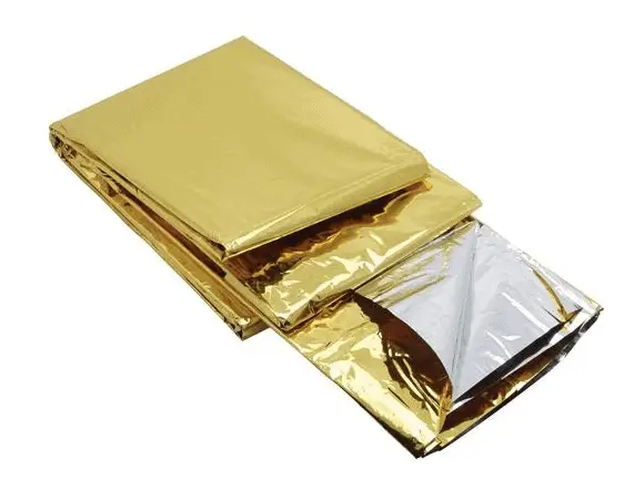
So far we have not discussed thermal radiation as a mode of heat losses. Radiation heat transfer is mediated by electromagnetic radiation and therefore it does not require any medium for heat transfer. In fact, energy transfer by radiation is fastest (at the speed of light) and it suffers no attenuation in a vacuum. Any material that has a temperature above absolute zero gives off some radiant energy. Most energy of this type is in the infra-red region of the electromagnetic spectrum although some of it is in the visible region. In order to decrease this type of heat transfer, materials with low emissivity should be used. The emissivity, ε, of the surface of a material is its effectiveness in emitting energy as thermal radiation and varies between 0.0 and 1.0. In general, polished metals have very low emissivity and therefore are widely used to reflect radiant energy back to its source as in case of first aid blankets.

Thermal Insulator

Thermal Insulators - ParametersAs was written, thermal insulation is based on the use of substances with very low thermal conductivity. These materials are known as thermal insulators. Common thermal insulators are wool, fiberglass, rock wool, polystyrene, polyurethane, and goose feather etc. These materials are very poor conductors of heat and are therefore good thermal insulators.

It must be added, thermal insulation is primarily based on the very low thermal conductivity of gases. Gases possess poor thermal conduction properties compared to liquids and solids, and thus makes a good insulation material if they can be trapped (e.g. in a foam-like structure). Air and other gases are generally good insulators. But the main benefit is in the absence of convection. Therefore, many insulating materials (e.g.polystyrene) function simply by having a large number of gas-filled pockets which prevent large-scale convection. In all types of thermal insulation, evacuation of the air in the void space will further reduce the overall thermal conductivity of the insulator.

Alternation of gas pocket and solid material causes that the heat must be transferred through many interfaces causing rapid decrease in heat transfer coefficient.

In case of thermal radiation insulation, reflective insulations can be used. Reflective insulations are usually composed of multilayered, parallel foils of high reflectivity, which are spaced to reflect thermal radiation back to its source.

Example – Heat Loss through a Wall

heat loss through wall - example - calculationA major source of heat loss from a house is through walls. Calculate the rate of heat flux through a wall 3 m x 10 m in area (A = 30 m2). The wall is 15 cm thick (L1) and it is made of bricks with the thermal conductivity of k1 = 1.0 W/m.K (poor thermal insulator). Assume that, the indoor and the outdoor temperatures are 22°C and -8°C, and the convection heat transfer coefficients on the inner and the outer sides are h1 = 10 W/m2K and h2 = 30 W/m2K, respectively. Note that, these convection coefficients strongly depend especially on ambient and interior conditions (wind, humidity, etc.).

  1. Calculate the heat flux (heat loss) through this non-insulated wall.
  2. Now assume thermal insulation on the outer side of this wall. Use expanded polystyrene insulation 10 cm thick (L2) with the thermal conductivity of k2 = 0.03 W/m.K and calculate the heat flux (heat loss) through this composite wall.

Solution:

As was written, many of the heat transfer processes involve composite systems and even involve a combination of both conduction and convection. With these composite systems, it is often convenient to work with an overall heat transfer coefficient, known as a U-factor. The U-factor is defined by an expression analogous to Newton’s law of cooling:

u-factor - overall heat transfer coefficient

The overall heat transfer coefficient is related to the total thermal resistance and depends on the geometry of the problem.

  1. bare wall

Assuming one-dimensional heat transfer through the plane wall and disregarding radiation, the overall heat transfer coefficient can be calculated as:

overall heat transfer coefficient - heat loss calculation

The overall heat transfer coefficient is then:

U = 1 / (1/10 + 0.15/1 + 1/30) = 3.53 W/m2K

The heat flux can be then calculated simply as:

q = 3.53 [W/m2K] x 30 [K] = 105.9 W/m2

The total heat loss through this wall will be:

qloss = q . A = 105.9 [W/m2] x 30 [m2] = 3177W

  1. composite wall with thermal insulation

Assuming one-dimensional heat transfer through the plane composite wall, no thermal contact resistance and disregarding radiation, the overall heat transfer coefficient can be calculated as:

overall heat transfer coefficient - thermal insulation calculation

thermal insulation - expanded polystyreneThe overall heat transfer coefficient is then:

U = 1 / (1/10 + 0.15/1 + 0.1/0.03 + 1/30) = 0.276 W/m2K

The heat flux can be then calculated simply as:

q = 0.276 [W/m2K] x 30 [K] = 8.28 W/m2

The total heat loss through this wall will be:

qloss = q . A = 8.28 [W/m2] x 30 [m2] = 248 W

As can be seen, an addition of thermal insulator causes significant decrease in heat losses. It must be added, an addition of next layer of thermal insulator does not cause such high savings. This can be better seen from the thermal resistance method, which can be used to calculate the heat transfer through composite walls. The rate of steady heat transfer between two surfaces is equal to the temperature difference divided by the total thermal resistance between those two surfaces.

thermal resistance - equation

 
References:
Heat Transfer:
  1. Fundamentals of Heat and Mass Transfer, 7th Edition. Theodore L. Bergman, Adrienne S. Lavine, Frank P. Incropera. John Wiley & Sons, Incorporated, 2011. ISBN: 9781118137253.
  2. Heat and Mass Transfer. Yunus A. Cengel. McGraw-Hill Education, 2011. ISBN: 9780071077866.
  3. U.S. Department of Energy, Thermodynamics, Heat Transfer and Fluid Flow. DOE Fundamentals Handbook, Volume 2 of 3. May 2016.

Nuclear and Reactor Physics:

  1. J. R. Lamarsh, Introduction to Nuclear Reactor Theory, 2nd ed., Addison-Wesley, Reading, MA (1983).
  2. J. R. Lamarsh, A. J. Baratta, Introduction to Nuclear Engineering, 3d ed., Prentice-Hall, 2001, ISBN: 0-201-82498-1.
  3. W. M. Stacey, Nuclear Reactor Physics, John Wiley & Sons, 2001, ISBN: 0- 471-39127-1.
  4. Glasstone, Sesonske. Nuclear Reactor Engineering: Reactor Systems Engineering, Springer; 4th edition, 1994, ISBN: 978-0412985317
  5. W.S.C. Williams. Nuclear and Particle Physics. Clarendon Press; 1 edition, 1991, ISBN: 978-0198520467
  6. G.R.Keepin. Physics of Nuclear Kinetics. Addison-Wesley Pub. Co; 1st edition, 1965
  7. Robert Reed Burn, Introduction to Nuclear Reactor Operation, 1988.
  8. U.S. Department of Energy, Nuclear Physics and Reactor Theory. DOE Fundamentals Handbook, Volume 1 and 2. January 1993.
  9. Paul Reuss, Neutron Physics. EDP Sciences, 2008. ISBN: 978-2759800414.

Advanced Reactor Physics:

  1. K. O. Ott, W. A. Bezella, Introductory Nuclear Reactor Statics, American Nuclear Society, Revised edition (1989), 1989, ISBN: 0-894-48033-2.
  2. K. O. Ott, R. J. Neuhold, Introductory Nuclear Reactor Dynamics, American Nuclear Society, 1985, ISBN: 0-894-48029-4.
  3. D. L. Hetrick, Dynamics of Nuclear Reactors, American Nuclear Society, 1993, ISBN: 0-894-48453-2.
  4. E. E. Lewis, W. F. Miller, Computational Methods of Neutron Transport, American Nuclear Society, 1993, ISBN: 0-894-48452-4.

See also:

Heat Losses

We hope, this article, Thermal Insulation – Thermal Insulator, helps you. If so, give us a like in the sidebar. Main purpose of this website is to help the public to learn some interesting and important information about thermal engineering.
What is Insulation Material – Types of Insulation – Definition

Common insulation materials are wool, fiberglass, rock wool, polystyrene, polyurethane, and goose feather etc. Insulation materials are very poor heat conductors. Thermal Engineering

Insulation Materials

Thermal Insulators - ParametersAs was written, thermal insulation is based on the use of substances with very low thermal conductivity. These materials are known as insulation materials. Common insulation materials are wool, fiberglass, rock wool, polystyrene, polyurethane, and goose feather etc. These materials are very poor conductors of heat and are therefore good thermal insulators.

It must be added, thermal insulation is primarily based on the very low thermal conductivity of gases. Gases possess poor thermal conduction properties compared to liquids and solids, and thus makes a good insulation material if they can be trapped (e.g. in a foam-like structure). Air and other gases are generally good insulators. But the main benefit is in the absence of convection. Therefore, many insulation materials (e.g.polystyrene) function simply by having a large number of gas-filled pockets which prevent large-scale convection. In all types of thermal insulation, evacuation of the air in the void space will further reduce the overall thermal conductivity of the insulator.

Alternation of gas pocket and solid material causes that the heat must be transferred through many interfaces causing rapid decrease in heat transfer coefficient.

It must be noted, heat losses from hotter objects occurs by three mechanisms (either individually or in combination):

So far we have not discussed thermal radiation as a mode of heat losses. Radiation heat transfer is mediated by electromagnetic radiation and therefore it does not require any medium for heat transfer. In fact, energy transfer by radiation is fastest (at the speed of light) and it suffers no attenuation in a vacuum. Any material that has a temperature above absolute zero gives off some radiant energy. Most energy of this type is in the infra-red region of the electromagnetic spectrum although some of it is in the visible region. In order to decrease this type of heat transfer, materials with low emissivity (high reflectivity) should be used. Reflective insulations are usually composed of multilayered, parallel foils of high reflectivity, which are spaced to reflect thermal radiation back to its source. The emissivity, ε, of the surface of a material is its effectiveness in emitting energy as thermal radiation and varies between 0.0 and 1.0. In general, polished metals have very low emissivity and therefore are widely used to reflect radiant energy back to its source as in case of first aid blankets.

Types of Insulation – Categorization of Insulation Materials

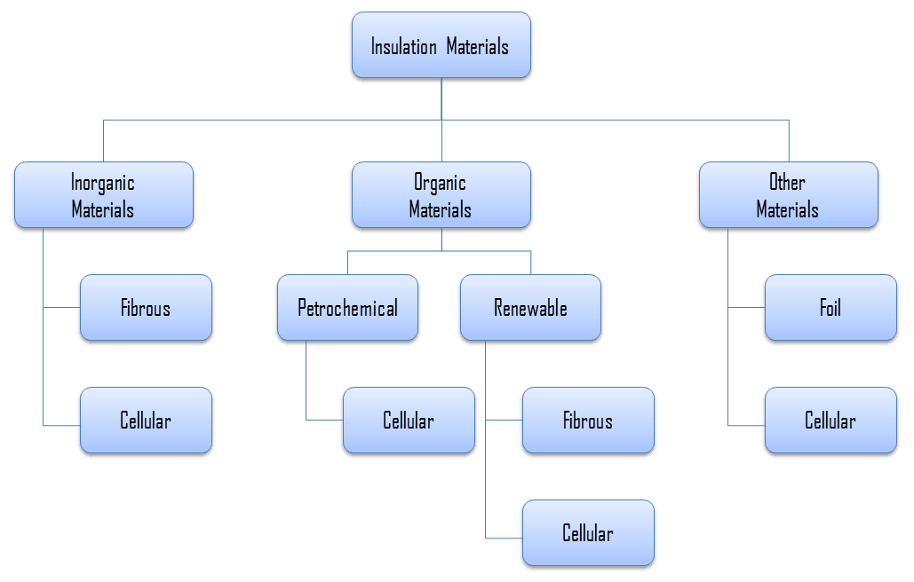
For insulation materials, three general categories can be defined. These categories are based on the chemical composition of the base material from which the insulating material is produced.

Insulation Materials - Types

In further reading, there is a brief description of these types of insulation materials.

Inorganic Insulation Materials

As can be seen from the figure, inorganic materials can be classified accordingly:

Organic Insulation Materials

The organic insulation materials treated in this section are all derived from a petrochemical or renewable feedstock (bio-based). Almost all of the petrochemical insulation materials are in the form of polymers. As can be see from the figure, all petrochemical insulation materials are cellular. A material is cellular when the structure of the material consists of pores or cells. On the other hand, many plants contain fibres for their strength, therefore almost all the bio-based insulation materials are fibrous (except expanded cork, which is cellular).

Organic insulation materials can be classified accordingly:

Other Insulation Materials

Example of Insulation – Polystyrene

Generally, polystyrene is a synthetic aromatic polymer made from the monomer styrene, which is derived from benzene and ethylene, both petroleum products. Polystyrene can be solid or foamed. Polystyrene is a colorless, transparent thermoplastic, which is commonly used to make foam board or beadboard insulation and a type of loose-fill insulation consisting of small beads of polystyrene. Polystyrene foams are 95-98% air. Polystyrene foams are good thermal insulators and are therefore often used as building insulation materials, such as in insulating concrete forms and structural insulated panel building systems. Expanded (EPS) and extruded polystyrene (XPS) are both made from polystyrene, but EPS is composed of small plastic beads that are fused together and XPS begins as a molten material that is pressed out of a form into sheets. XPS is most commonly used as foam board insulation.

expanded polystyrene - thermal insulationExpanded polystyrene (EPS) is a rigid and tough, closed-cell foam. Building and construction applications account for around two-thirds of demand for expanded polystyrene. It is used for the insulation of (cavity) walls, roofs and concrete floors. Due to its technical properties such as low weight, rigidity, and formability, expanded polystyrene can be used in a wide range of applications, for example trays, plates and fish boxes.

Although both expanded and extruded polystyrene have a closed-cell structure, they are permeable by water molecules and can not be considered a vapor barrier. In expanded polystyrene there are interstitial gaps between the expanded closed-cell pellets that form an open network of channels between the bonded pellets. If the water freezes into ice, it expands and can cause polystyrene pellets to break off from the foam.

Example of Insulation – Vacuum Insulation Panels

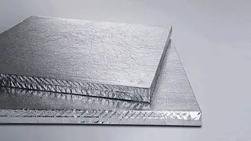
vacuum insulation panelsMost materials are limited by thermal conductivity of the air (trapped in cells), which is about about 0.025 W/m∙K. But a decrease in pressure causes a decrease in its thermal conductivity. A vacuum insulation panel (VIP) reduces this problem. This panel is a form of thermal insulation consisting of a gas-tight enclosure surrounding a rigid core. The air from this panel is evacuated. It must be noted, aging has a negative effect on the panels. This is because the envelope of the panels is not fully airtight and therefore its thermal conductivity slightly increases. These panels can be used for the thermal insulation of almost every element of the building envelope.

Example – Heat Loss through a Wall

heat loss through wall - example - calculationA major source of heat loss from a house is through walls. Calculate the rate of heat flux through a wall 3 m x 10 m in area (A = 30 m2). The wall is 15 cm thick (L1) and it is made of bricks with the thermal conductivity of k1 = 1.0 W/m.K (poor thermal insulator). Assume that, the indoor and the outdoor temperatures are 22°C and -8°C, and the convection heat transfer coefficients on the inner and the outer sides are h1 = 10 W/m2K and h2 = 30 W/m2K, respectively. Note that, these convection coefficients strongly depend especially on ambient and interior conditions (wind, humidity, etc.).

  1. Calculate the heat flux (heat loss) through this non-insulated wall.
  2. Now assume thermal insulation on the outer side of this wall. Use expanded polystyrene insulation 10 cm thick (L2) with the thermal conductivity of k2 = 0.03 W/m.K and calculate the heat flux (heat loss) through this composite wall.

Solution:

As was written, many of the heat transfer processes involve composite systems and even involve a combination of both conduction and convection. With these composite systems, it is often convenient to work with an overall heat transfer coefficient, known as a U-factor. The U-factor is defined by an expression analogous to Newton’s law of cooling:

u-factor - overall heat transfer coefficient

The overall heat transfer coefficient is related to the total thermal resistance and depends on the geometry of the problem.

  1. bare wall

Assuming one-dimensional heat transfer through the plane wall and disregarding radiation, the overall heat transfer coefficient can be calculated as:

overall heat transfer coefficient - heat loss calculation

The overall heat transfer coefficient is then:

U = 1 / (1/10 + 0.15/1 + 1/30) = 3.53 W/m2K

The heat flux can be then calculated simply as:

q = 3.53 [W/m2K] x 30 [K] = 105.9 W/m2

The total heat loss through this wall will be:

qloss = q . A = 105.9 [W/m2] x 30 [m2] = 3177W

  1. composite wall with thermal insulation

Assuming one-dimensional heat transfer through the plane composite wall, no thermal contact resistance and disregarding radiation, the overall heat transfer coefficient can be calculated as:

overall heat transfer coefficient - thermal insulation calculation

thermal insulation - expanded polystyreneThe overall heat transfer coefficient is then:

U = 1 / (1/10 + 0.15/1 + 0.1/0.03 + 1/30) = 0.276 W/m2K

The heat flux can be then calculated simply as:

q = 0.276 [W/m2K] x 30 [K] = 8.28 W/m2

The total heat loss through this wall will be:

qloss = q . A = 8.28 [W/m2] x 30 [m2] = 248 W

As can be seen, an addition of thermal insulator causes significant decrease in heat losses. It must be added, an addition of next layer of thermal insulator does not cause such high savings. This can be better seen from the thermal resistance method, which can be used to calculate the heat transfer through composite walls. The rate of steady heat transfer between two surfaces is equal to the temperature difference divided by the total thermal resistance between those two surfaces.

thermal resistance - equation

 
References:
Heat Transfer:
  1. Fundamentals of Heat and Mass Transfer, 7th Edition. Theodore L. Bergman, Adrienne S. Lavine, Frank P. Incropera. John Wiley & Sons, Incorporated, 2011. ISBN: 9781118137253.
  2. Heat and Mass Transfer. Yunus A. Cengel. McGraw-Hill Education, 2011. ISBN: 9780071077866.
  3. U.S. Department of Energy, Thermodynamics, Heat Transfer and Fluid Flow. DOE Fundamentals Handbook, Volume 2 of 3. May 2016.

Nuclear and Reactor Physics:

  1. J. R. Lamarsh, Introduction to Nuclear Reactor Theory, 2nd ed., Addison-Wesley, Reading, MA (1983).
  2. J. R. Lamarsh, A. J. Baratta, Introduction to Nuclear Engineering, 3d ed., Prentice-Hall, 2001, ISBN: 0-201-82498-1.
  3. W. M. Stacey, Nuclear Reactor Physics, John Wiley & Sons, 2001, ISBN: 0- 471-39127-1.
  4. Glasstone, Sesonske. Nuclear Reactor Engineering: Reactor Systems Engineering, Springer; 4th edition, 1994, ISBN: 978-0412985317
  5. W.S.C. Williams. Nuclear and Particle Physics. Clarendon Press; 1 edition, 1991, ISBN: 978-0198520467
  6. G.R.Keepin. Physics of Nuclear Kinetics. Addison-Wesley Pub. Co; 1st edition, 1965
  7. Robert Reed Burn, Introduction to Nuclear Reactor Operation, 1988.
  8. U.S. Department of Energy, Nuclear Physics and Reactor Theory. DOE Fundamentals Handbook, Volume 1 and 2. January 1993.
  9. Paul Reuss, Neutron Physics. EDP Sciences, 2008. ISBN: 978-2759800414.

Advanced Reactor Physics:

  1. K. O. Ott, W. A. Bezella, Introductory Nuclear Reactor Statics, American Nuclear Society, Revised edition (1989), 1989, ISBN: 0-894-48033-2.
  2. K. O. Ott, R. J. Neuhold, Introductory Nuclear Reactor Dynamics, American Nuclear Society, 1985, ISBN: 0-894-48029-4.
  3. D. L. Hetrick, Dynamics of Nuclear Reactors, American Nuclear Society, 1993, ISBN: 0-894-48453-2.
  4. E. E. Lewis, W. F. Miller, Computational Methods of Neutron Transport, American Nuclear Society, 1993, ISBN: 0-894-48452-4.

See also:

Heat Losses

We hope, this article, Insulation Material – Types of Insulation, helps you. If so, give us a like in the sidebar. Main purpose of this website is to help the public to learn some interesting and important information about thermal engineering.
What is Main Property of Insulation Materials – Definition

Key properties of insulation materials are: thermal conductivity, R-value, U-value, surface emissivity and fire resistance. Properties and characteristics of Insulation Materials

Properties of Insulation Materials

Thermal insulation is based on the use of substances with very low thermal conductivity and low surface emissivity. It is important to note that the factors influencing performance may vary over time as material ages or environmental conditions change. Key properties of insulation materials are:

  • Thermal Conductivity. Thermal conductivity,  measured in W/mK describes how well a material conducts heat. Note that Fourier’s law applies for all matter, regardless of its state (solid, liquid, or gas), therefore, it is also defined for liquids and gases. It is the amount of heat (in watts) transferred through a square area of material of given thickness (in metres) due to a difference in temperature. The lower the thermal conductivity of the material the greater the material’s ability to resist heat transfer, and hence the greater the insulation’s effectiveness. In general, gases have a low thermal conductivity (e.g. air has 0.025 W/mK) whilst metals has a high values (e.g. copper has 400 W/mK). Commonly used insulants tend to have a thermal conductivity between 0.019 W/mK and 0.046 W/mK.
  • R-Value – Thermal Resistance. R-value (thermal insulance factor) is a measure of thermal resistance. The higher the R-value, the greater the insulating effectiveness. Thermal insulance has the units [(m2.K)/W] in SI units or [(ft2·°F·hr)/Btu] in imperial units. It is the thermal resistance of unit area of a material. The R-value depends on the type of insulation, its thickness, and its density. An area and a temperature difference is required to solve for heat transferred. The construction industry makes use of units such as the R-value (resistance), which is expressed as the thickness of the material normalized to the thermal conductivity, and under uniform conditions it is the ratio of the temperature difference across an insulator and the heat flux density through it: R(x) = ∆T/q. The higher the R-value, the more a material prevents heat transfer. As can be seen, the resistance is dependent on the thickness of the product.
  • U-value – Thermal Transmittance.  Thermal Transmittance describes how well the material conducts heat.  Thermal Transmittance is the inverse of the R-value (i.e. 1/R) and the lower the U-value the better the insulation. The U-value is defined by an expression analogous to Newton’s law of cooling.
  • Surface Emissivity. As was written, heat transfer through any of these insulation systems may include several modes: conduction through the solid materials, conduction or convection through the air in the void spaces and radiation exchange between the surfaces of the solid matrix. Therefore the emissivity of a material plays also very important role. The emissivity, ε, of the surface of a material is its effectiveness in emitting energy as thermal radiation and varies between 0.0 and 1.0. Emissivity is simply a factor by which we multiply the black body heat transfer to take into account that the black body is the ideal case. The surface of a blackbody emits thermal radiation at the rate of approximately 448 watts per square metre at room temperature (25 °C, 298.15 K). Real objects with emissivities less than 1.0 (e.g. aluminium foil) emit radiation at correspondingly lower rates (e.g. 448 x 0.07 = 31.4 W/m2).
  • Fire resisitance. Thermal insulating materials must have a fire resistance classification. This classification is important because it can be of influence on the application of insulating materials. Normally the fire resistance classification is followed by as a time limit in minutes 15, 30, 45, 60, 90, 120, 180, 240, or 360 which shows the time the performance criteria is fulfilled during a standardized fire test.

Insulation Materials

Thermal Insulators - ParametersAs was written, thermal insulation is based on the use of substances with very low thermal conductivity. These materials are known as insulation materials. Common insulation materials are wool, fiberglass, rock wool, polystyrene, polyurethane, and goose feather etc. These materials are very poor conductors of heat and are therefore good thermal insulators.

It must be added, thermal insulation is primarily based on the very low thermal conductivity of gases. Gases possess poor thermal conduction properties compared to liquids and solids, and thus makes a good insulation material if they can be trapped (e.g. in a foam-like structure). Air and other gases are generally good insulators. But the main benefit is in the absence of convection. Therefore, many insulation materials (e.g.polystyrene) function simply by having a large number of gas-filled pockets which prevent large-scale convection. In all types of thermal insulation, evacuation of the air in the void space will further reduce the overall thermal conductivity of the insulator.

Alternation of gas pocket and solid material causes that the heat must be transferred through many interfaces causing rapid decrease in heat transfer coefficient.

It must be noted, heat losses from hotter objects occurs by three mechanisms (either individually or in combination):

So far we have not discussed thermal radiation as a mode of heat losses. Radiation heat transfer is mediated by electromagnetic radiation and therefore it does not require any medium for heat transfer. In fact, energy transfer by radiation is fastest (at the speed of light) and it suffers no attenuation in a vacuum. Any material that has a temperature above absolute zero gives off some radiant energy. Most energy of this type is in the infra-red region of the electromagnetic spectrum although some of it is in the visible region. In order to decrease this type of heat transfer, materials with low emissivity (high reflectivity) should be used. Reflective insulations are usually composed of multilayered, parallel foils of high reflectivity, which are spaced to reflect thermal radiation back to its source. The emissivity, ε, of the surface of a material is its effectiveness in emitting energy as thermal radiation and varies between 0.0 and 1.0. In general, polished metals have very low emissivity and therefore are widely used to reflect radiant energy back to its source as in case of first aid blankets.

Critical Thickness of Insulation

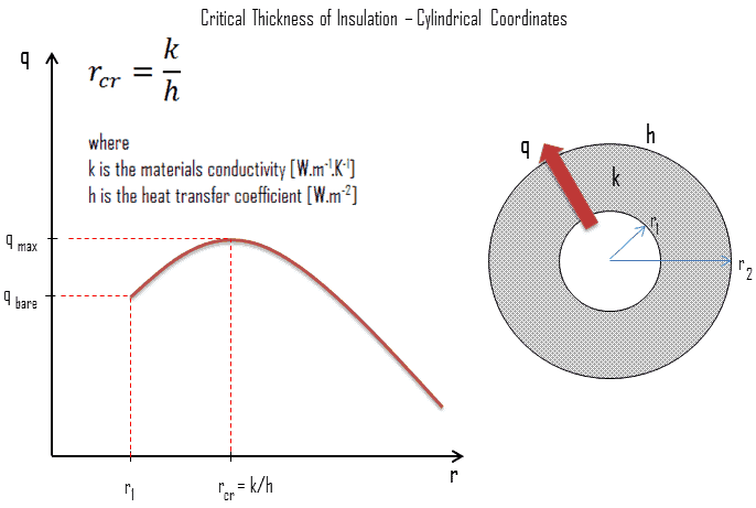
Critical Thickness InsulationIn a plane wall the area perpendicular to the direction of heat flow adding more insulation to a wall always decreases heat transfer. The thicker the insulation, the lower the heat transfer rate. This is due to the fact the outer surface have always the same area.

But in cylindrical and spherical coordinates, the addition of insulation also increases the outer surface, which decreases the convection resistance at the outer surface. Moreover, in some cases, a decrease in the convection resistance due to the increase in surface area can be more important than an increase in conduction resistance due to thicker insulation. As a result the total resistance may actually decrease resulting in increased heat flow.

The thickness upto which heat flow increases and after which heat flow decreases is termed as critical thickness. In the case of cylinders and spheres it is called critical radius. It can be derived the critical radius of insulation depends on the thermal conductivity of the insulation k and the external convection heat transfer coefficient h.

See also: Critical radius of insulation

Example – Heat Loss through a Wall

heat loss through wall - example - calculationA major source of heat loss from a house is through walls. Calculate the rate of heat flux through a wall 3 m x 10 m in area (A = 30 m2). The wall is 15 cm thick (L1) and it is made of bricks with the thermal conductivity of k1 = 1.0 W/m.K (poor thermal insulator). Assume that, the indoor and the outdoor temperatures are 22°C and -8°C, and the convection heat transfer coefficients on the inner and the outer sides are h1 = 10 W/m2K and h2 = 30 W/m2K, respectively. Note that, these convection coefficients strongly depend especially on ambient and interior conditions (wind, humidity, etc.).

  1. Calculate the heat flux (heat loss) through this non-insulated wall.
  2. Now assume thermal insulation on the outer side of this wall. Use expanded polystyrene insulation 10 cm thick (L2) with the thermal conductivity of k2 = 0.03 W/m.K and calculate the heat flux (heat loss) through this composite wall.

Solution:

As was written, many of the heat transfer processes involve composite systems and even involve a combination of both conduction and convection. With these composite systems, it is often convenient to work with an overall heat transfer coefficient, known as a U-factor. The U-factor is defined by an expression analogous to Newton’s law of cooling:

u-factor - overall heat transfer coefficient

The overall heat transfer coefficient is related to the total thermal resistance and depends on the geometry of the problem.

  1. bare wall

Assuming one-dimensional heat transfer through the plane wall and disregarding radiation, the overall heat transfer coefficient can be calculated as:

overall heat transfer coefficient - heat loss calculation

The overall heat transfer coefficient is then:

U = 1 / (1/10 + 0.15/1 + 1/30) = 3.53 W/m2K

The heat flux can be then calculated simply as:

q = 3.53 [W/m2K] x 30 [K] = 105.9 W/m2

The total heat loss through this wall will be:

qloss = q . A = 105.9 [W/m2] x 30 [m2] = 3177W

  1. composite wall with thermal insulation

Assuming one-dimensional heat transfer through the plane composite wall, no thermal contact resistance and disregarding radiation, the overall heat transfer coefficient can be calculated as:

overall heat transfer coefficient - thermal insulation calculation

thermal insulation - expanded polystyreneThe overall heat transfer coefficient is then:

U = 1 / (1/10 + 0.15/1 + 0.1/0.03 + 1/30) = 0.276 W/m2K

The heat flux can be then calculated simply as:

q = 0.276 [W/m2K] x 30 [K] = 8.28 W/m2

The total heat loss through this wall will be:

qloss = q . A = 8.28 [W/m2] x 30 [m2] = 248 W

As can be seen, an addition of thermal insulator causes significant decrease in heat losses. It must be added, an addition of next layer of thermal insulator does not cause such high savings. This can be better seen from the thermal resistance method, which can be used to calculate the heat transfer through composite walls. The rate of steady heat transfer between two surfaces is equal to the temperature difference divided by the total thermal resistance between those two surfaces.

thermal resistance - equation

 
References:
Heat Transfer:
  1. Fundamentals of Heat and Mass Transfer, 7th Edition. Theodore L. Bergman, Adrienne S. Lavine, Frank P. Incropera. John Wiley & Sons, Incorporated, 2011. ISBN: 9781118137253.
  2. Heat and Mass Transfer. Yunus A. Cengel. McGraw-Hill Education, 2011. ISBN: 9780071077866.
  3. U.S. Department of Energy, Thermodynamics, Heat Transfer and Fluid Flow. DOE Fundamentals Handbook, Volume 2 of 3. May 2016.

Nuclear and Reactor Physics:

  1. J. R. Lamarsh, Introduction to Nuclear Reactor Theory, 2nd ed., Addison-Wesley, Reading, MA (1983).
  2. J. R. Lamarsh, A. J. Baratta, Introduction to Nuclear Engineering, 3d ed., Prentice-Hall, 2001, ISBN: 0-201-82498-1.
  3. W. M. Stacey, Nuclear Reactor Physics, John Wiley & Sons, 2001, ISBN: 0- 471-39127-1.
  4. Glasstone, Sesonske. Nuclear Reactor Engineering: Reactor Systems Engineering, Springer; 4th edition, 1994, ISBN: 978-0412985317
  5. W.S.C. Williams. Nuclear and Particle Physics. Clarendon Press; 1 edition, 1991, ISBN: 978-0198520467
  6. G.R.Keepin. Physics of Nuclear Kinetics. Addison-Wesley Pub. Co; 1st edition, 1965
  7. Robert Reed Burn, Introduction to Nuclear Reactor Operation, 1988.
  8. U.S. Department of Energy, Nuclear Physics and Reactor Theory. DOE Fundamentals Handbook, Volume 1 and 2. January 1993.
  9. Paul Reuss, Neutron Physics. EDP Sciences, 2008. ISBN: 978-2759800414.

Advanced Reactor Physics:

  1. K. O. Ott, W. A. Bezella, Introductory Nuclear Reactor Statics, American Nuclear Society, Revised edition (1989), 1989, ISBN: 0-894-48033-2.
  2. K. O. Ott, R. J. Neuhold, Introductory Nuclear Reactor Dynamics, American Nuclear Society, 1985, ISBN: 0-894-48029-4.
  3. D. L. Hetrick, Dynamics of Nuclear Reactors, American Nuclear Society, 1993, ISBN: 0-894-48453-2.
  4. E. E. Lewis, W. F. Miller, Computational Methods of Neutron Transport, American Nuclear Society, 1993, ISBN: 0-894-48452-4.

See also:

Heat Losses

We hope, this article, Main Property of Insulation Materials, helps you. If so, give us a like in the sidebar. Main purpose of this website is to help the public to learn some interesting and important information about thermal engineering.

What is Application of Thermal Insulators – Definition

Applications of Thermal Insulators. The purpose of clothing is similar as the purpose of building insulation. The purpose of thermal insulation is to reduce the overall heat transfer coefficient by adding materials with low thermal conductivity. Thermal Engineering

Applications of Thermal Insulators

Clothing

The purpose of clothing is similar. The insulating properties of clothing come from the insulating properties of air. Gases possess poor thermal conduction properties compared to liquids and solids, and thus makes a good insulation material if they can be trapped (e.g. in a foam-like structure). Air and other gases are generally good insulators. But the main benefit is in the absence of convection. Without clothes, our bodies in still air would heat the air in direct contact with the skin and would soon become reasonably comfortable because air is a very good insulator. It must be added, also in this case air will be flowing due to natural convection. In natural convection, air surrounding a body receives heat and by thermal expansion becomes less dense and rises. Thermal expansion of air plays a crucial role. In other words, heavier (more dense) components will fall, while lighter (less dense) components rise, leading to bulk air movement.

In the wind, the warm air surrounding our body would be replaced by cold air, thus increasing the temperature difference and the heat loss from the body. Clothes constitute a barrier to this moving air. The main benefit is in the absence of large-scale convection. Moreover, clothes are made from materials, which are generally good insulators. Many insulating materials (e.g. wool) function simply by having a large number of gas-filled pockets which prevent large-scale convection. Alternation of gas pocket and solid material causes that the heat must be transferred through many interfaces causing rapid decrease in heat transfer coefficient.

Building Insulation

In order to minimize heat losses in industry and also in construction of buildings, thermal insulation is widely used. The purpose of thermal insulation is to reduce the overall heat transfer coefficient by adding materials with low thermal conductivity.  Thermal insulation in buildings is an important factor to achieving thermal comfort for its occupants. Thermal insulation reduces unwanted heat loss and also reduce unwanted heat gain. Therefore thermal insulation can decrease the energy demands of heating and cooling systems. It must be added, there is no material which can completely prevent heat losses, heat losses can be only minimized.

Similarly as for clothing, thermal insulation is based on low thermal conductivity materials and on its geometry (e.g. double-pane windows). The insulating properties of these materials come from the insulating properties of air. Many insulating materials (e.g. wool) function simply by having a large number of gas-filled pockets which prevent large-scale convection. Geometry of these materials plays also crucial role. For example,  increasing the width of the air layer, such as using two panes of glass separated by an air gap, will reduce the heat loss more than simply increasing the glass thickness, since the thermal conductivity of air is much less than that for glass.

 
References:
Heat Transfer:
  1. Fundamentals of Heat and Mass Transfer, 7th Edition. Theodore L. Bergman, Adrienne S. Lavine, Frank P. Incropera. John Wiley & Sons, Incorporated, 2011. ISBN: 9781118137253.
  2. Heat and Mass Transfer. Yunus A. Cengel. McGraw-Hill Education, 2011. ISBN: 9780071077866.
  3. U.S. Department of Energy, Thermodynamics, Heat Transfer and Fluid Flow. DOE Fundamentals Handbook, Volume 2 of 3. May 2016.

Nuclear and Reactor Physics:

  1. J. R. Lamarsh, Introduction to Nuclear Reactor Theory, 2nd ed., Addison-Wesley, Reading, MA (1983).
  2. J. R. Lamarsh, A. J. Baratta, Introduction to Nuclear Engineering, 3d ed., Prentice-Hall, 2001, ISBN: 0-201-82498-1.
  3. W. M. Stacey, Nuclear Reactor Physics, John Wiley & Sons, 2001, ISBN: 0- 471-39127-1.
  4. Glasstone, Sesonske. Nuclear Reactor Engineering: Reactor Systems Engineering, Springer; 4th edition, 1994, ISBN: 978-0412985317
  5. W.S.C. Williams. Nuclear and Particle Physics. Clarendon Press; 1 edition, 1991, ISBN: 978-0198520467
  6. G.R.Keepin. Physics of Nuclear Kinetics. Addison-Wesley Pub. Co; 1st edition, 1965
  7. Robert Reed Burn, Introduction to Nuclear Reactor Operation, 1988.
  8. U.S. Department of Energy, Nuclear Physics and Reactor Theory. DOE Fundamentals Handbook, Volume 1 and 2. January 1993.
  9. Paul Reuss, Neutron Physics. EDP Sciences, 2008. ISBN: 978-2759800414.

Advanced Reactor Physics:

  1. K. O. Ott, W. A. Bezella, Introductory Nuclear Reactor Statics, American Nuclear Society, Revised edition (1989), 1989, ISBN: 0-894-48033-2.
  2. K. O. Ott, R. J. Neuhold, Introductory Nuclear Reactor Dynamics, American Nuclear Society, 1985, ISBN: 0-894-48029-4.
  3. D. L. Hetrick, Dynamics of Nuclear Reactors, American Nuclear Society, 1993, ISBN: 0-894-48453-2.
  4. E. E. Lewis, W. F. Miller, Computational Methods of Neutron Transport, American Nuclear Society, 1993, ISBN: 0-894-48452-4.

See also:

Heat Losses

We hope, this article, Application of Thermal Insulators, helps you. If so, give us a like in the sidebar. Main purpose of this website is to help the public to learn some interesting and important information about thermal engineering.
What is Building Insulation – Home Insulation – Definition

Building Insulation – Home Insulation. In order to minimize heat losses in industry and also in construction of buildings, thermal insulation is widely used. Thermal Engineering

Building Insulation – Home Insulation

In order to minimize heat losses in industry and also in construction of buildings, thermal insulation is widely used. The purpose of thermal insulation of is to reduce the overall heat transfer coefficient by adding materials with low thermal conductivity.  Thermal insulation in buildings is an important factor to achieving thermal comfort for its occupants. Thermal insulation reduces unwanted heat loss and also reduce unwanted heat gain. Therefore thermal insulation can decrease the energy demands of heating and cooling systems. It must be added, there is no material which can completely prevent heat losses, heat losses can be only minimized.

Similarly as for clothing, thermal insulation is based on low thermal conductivity materials and on its geometry (e.g. double-pane windows). The insulating properties of these materials come from the insulating properties of air. Many insulating materials (e.g. wool) function simply by having a large number of gas-filled pockets which prevent large-scale convection. Geometry of these materials plays also crucial role. For example,  increasing the width of the air layer, such as using two panes of glass separated by an air gap, will reduce the heat loss more than simply increasing the glass thickness, since the thermal conductivity of air is much less than that for glass.

Insulation Materials

Thermal Insulators - ParametersAs was written, thermal insulation is based on the use of substances with very low thermal conductivity. These materials are known as insulation materials. Common insulation materials are wool, fiberglass, rock wool, polystyrene, polyurethane, and goose feather etc. These materials are very poor conductors of heat and are therefore good thermal insulators.

It must be added, thermal insulation is primarily based on the very low thermal conductivity of gases. Gases possess poor thermal conduction properties compared to liquids and solids, and thus makes a good insulation material if they can be trapped (e.g. in a foam-like structure). Air and other gases are generally good insulators. But the main benefit is in the absence of convection. Therefore, many insulation materials (e.g.polystyrene) function simply by having a large number of gas-filled pockets which prevent large-scale convection. In all types of thermal insulation, evacuation of the air in the void space will further reduce the overall thermal conductivity of the insulator.

Alternation of gas pocket and solid material causes that the heat must be transferred through many interfaces causing rapid decrease in heat transfer coefficient.

It must be noted, heat losses from hotter objects occurs by three mechanisms (either individually or in combination):

So far we have not discussed thermal radiation as a mode of heat losses. Radiation heat transfer is mediated by electromagnetic radiation and therefore it does not require any medium for heat transfer. In fact, energy transfer by radiation is fastest (at the speed of light) and it suffers no attenuation in a vacuum. Any material that has a temperature above absolute zero gives off some radiant energy. Most energy of this type is in the infra-red region of the electromagnetic spectrum although some of it is in the visible region. In order to decrease this type of heat transfer, materials with low emissivity (high reflectivity) should be used. Reflective insulations are usually composed of multilayered, parallel foils of high reflectivity, which are spaced to reflect thermal radiation back to its source. The emissivity, ε, of the surface of a material is its effectiveness in emitting energy as thermal radiation and varies between 0.0 and 1.0. In general, polished metals have very low emissivity and therefore are widely used to reflect radiant energy back to its source as in case of first aid blankets.

Types of Insulation – Categorization of Insulation Materials

For insulation materials, three general categories can be defined. These categories are based on the chemical composition of the base material from which the insulating material is produced.

Insulation Materials - Types

In further reading, there is a brief description of these types of insulation materials.

Inorganic Insulation Materials

As can be seen from the figure, inorganic materials can be classified accordingly:

  • Fibrous materials
    • Glass wool
    • Rock wool
  • Cellular materials
    • Calcium silicate
    • Cellular glass

Organic Insulation Materials

The organic insulation materials treated in this section are all derived from a petrochemical or renewable feedstock (bio-based). Almost all of the petrochemical insulation materials are in the form of polymers. As can be see from the figure, all petrochemical insulation materials are cellular. A material is cellular when the structure of the material consists of pores or cells. On the other hand, many plants contain fibres for their strength, therefore almost all the bio-based insulation materials are fibrous (except expanded cork, which is cellular).

Organic insulation materials can be classified accordingly:

  • Petrochemical materials (oil/coal derived)
    • Expanded polystyrene (EPS)
    • Extruded polystyrene (XPS)
    • Polyurethane (PUR)
    • Phenolic foam
    • Polyisocyanurate foam (PIR)
  • Renewable materials (plant/animal derived)
    • Cellulose
    • Cork
    • Woodfibre
    • Hemp fibre
    • Flax wool
    • Sheeps wool
    • Cotton insulation

Example – Heat Loss through a Wall

heat loss through wall - example - calculationA major source of heat loss from a house is through walls. Calculate the rate of heat flux through a wall 3 m x 10 m in area (A = 30 m2). The wall is 15 cm thick (L1) and it is made of bricks with the thermal conductivity of k1 = 1.0 W/m.K (poor thermal insulator). Assume that, the indoor and the outdoor temperatures are 22°C and -8°C, and the convection heat transfer coefficients on the inner and the outer sides are h1 = 10 W/m2K and h2 = 30 W/m2K, respectively. Note that, these convection coefficients strongly depend especially on ambient and interior conditions (wind, humidity, etc.).

  1. Calculate the heat flux (heat loss) through this non-insulated wall.
  2. Now assume thermal insulation on the outer side of this wall. Use expanded polystyrene insulation 10 cm thick (L2) with the thermal conductivity of k2 = 0.03 W/m.K and calculate the heat flux (heat loss) through this composite wall.

Solution:

As was written, many of the heat transfer processes involve composite systems and even involve a combination of both conduction and convection. With these composite systems, it is often convenient to work with an overall heat transfer coefficient, known as a U-factor. The U-factor is defined by an expression analogous to Newton’s law of cooling:

u-factor - overall heat transfer coefficient

The overall heat transfer coefficient is related to the total thermal resistance and depends on the geometry of the problem.

  1. bare wall

Assuming one-dimensional heat transfer through the plane wall and disregarding radiation, the overall heat transfer coefficient can be calculated as:

overall heat transfer coefficient - heat loss calculation

The overall heat transfer coefficient is then:

U = 1 / (1/10 + 0.15/1 + 1/30) = 3.53 W/m2K

The heat flux can be then calculated simply as:

q = 3.53 [W/m2K] x 30 [K] = 105.9 W/m2

The total heat loss through this wall will be:

qloss = q . A = 105.9 [W/m2] x 30 [m2] = 3177W

  1. composite wall with thermal insulation

Assuming one-dimensional heat transfer through the plane composite wall, no thermal contact resistance and disregarding radiation, the overall heat transfer coefficient can be calculated as:

overall heat transfer coefficient - thermal insulation calculation

thermal insulation - expanded polystyreneThe overall heat transfer coefficient is then:

U = 1 / (1/10 + 0.15/1 + 0.1/0.03 + 1/30) = 0.276 W/m2K

The heat flux can be then calculated simply as:

q = 0.276 [W/m2K] x 30 [K] = 8.28 W/m2

The total heat loss through this wall will be:

qloss = q . A = 8.28 [W/m2] x 30 [m2] = 248 W

As can be seen, an addition of thermal insulator causes significant decrease in heat losses. It must be added, an addition of next layer of thermal insulator does not cause such high savings. This can be better seen from the thermal resistance method, which can be used to calculate the heat transfer through composite walls. The rate of steady heat transfer between two surfaces is equal to the temperature difference divided by the total thermal resistance between those two surfaces.

thermal resistance - equation

 
References:
Heat Transfer:
  1. Fundamentals of Heat and Mass Transfer, 7th Edition. Theodore L. Bergman, Adrienne S. Lavine, Frank P. Incropera. John Wiley & Sons, Incorporated, 2011. ISBN: 9781118137253.
  2. Heat and Mass Transfer. Yunus A. Cengel. McGraw-Hill Education, 2011. ISBN: 9780071077866.
  3. U.S. Department of Energy, Thermodynamics, Heat Transfer and Fluid Flow. DOE Fundamentals Handbook, Volume 2 of 3. May 2016.

Nuclear and Reactor Physics:

  1. J. R. Lamarsh, Introduction to Nuclear Reactor Theory, 2nd ed., Addison-Wesley, Reading, MA (1983).
  2. J. R. Lamarsh, A. J. Baratta, Introduction to Nuclear Engineering, 3d ed., Prentice-Hall, 2001, ISBN: 0-201-82498-1.
  3. W. M. Stacey, Nuclear Reactor Physics, John Wiley & Sons, 2001, ISBN: 0- 471-39127-1.
  4. Glasstone, Sesonske. Nuclear Reactor Engineering: Reactor Systems Engineering, Springer; 4th edition, 1994, ISBN: 978-0412985317
  5. W.S.C. Williams. Nuclear and Particle Physics. Clarendon Press; 1 edition, 1991, ISBN: 978-0198520467
  6. G.R.Keepin. Physics of Nuclear Kinetics. Addison-Wesley Pub. Co; 1st edition, 1965
  7. Robert Reed Burn, Introduction to Nuclear Reactor Operation, 1988.
  8. U.S. Department of Energy, Nuclear Physics and Reactor Theory. DOE Fundamentals Handbook, Volume 1 and 2. January 1993.
  9. Paul Reuss, Neutron Physics. EDP Sciences, 2008. ISBN: 978-2759800414.

Advanced Reactor Physics:

  1. K. O. Ott, W. A. Bezella, Introductory Nuclear Reactor Statics, American Nuclear Society, Revised edition (1989), 1989, ISBN: 0-894-48033-2.
  2. K. O. Ott, R. J. Neuhold, Introductory Nuclear Reactor Dynamics, American Nuclear Society, 1985, ISBN: 0-894-48029-4.
  3. D. L. Hetrick, Dynamics of Nuclear Reactors, American Nuclear Society, 1993, ISBN: 0-894-48453-2.
  4. E. E. Lewis, W. F. Miller, Computational Methods of Neutron Transport, American Nuclear Society, 1993, ISBN: 0-894-48452-4.

See also:

Heat Losses

We hope, this article, Building Insulation – Home Insulation, helps you. If so, give us a like in the sidebar. Main purpose of this website is to help the public to learn some interesting and important information about thermal engineering.

What is Space Blanket – Emergency Thermal Blanket – Definition

In order to insulate thermal radiation, space blankets (depending on the function, also known as a Mylar blanket, emergency thermal blanket or safety blanket) can be used. Thermal Engineering

Space Blanket – Emergency Thermal Blanket

emergency thermal blanket - space blanketAs was written, thermal insulation is based on the use of substances with very low thermal conductivity. But sometimes the most effective way to protect persons or devices from leakage or gain of heat is to use a thermal radiation insulator. Thermal radiation does not require any medium for energy transfer. Moreover, energy transfer by radiation is fastest (at the speed of light) and it suffers no attenuation in a vacuum.

In contrast to heat transfer by conduction or convection, which take place in the direction of decreasing temperature, thermal radiation heat transfer can occur between two bodies separated by a medium colder than both bodies. For example, solar radiation reaches the surface of the earth after passing through cold layers of atmosphere at high altitudes.

In order to insulate thermal radiation, space blankets (depending on the function, also known as a Mylar blanket, emergency thermal blanket or safety blanket) can be used. Space blankets were first developed by NASA in 1964. The highly reflective insulators are often included in emergency kits (therefore emergency thermal blankets) and are also used by long-distance runners after finishing a race to avoid a large swing in body temperature. Space blankets are designed to reflect heat back to body or deflect heat when used as a shelter from the sun, they can be used to insulate everything from the Mars rovers to marathon runners, from satellites to sun shields, and from rockets to residences. It is one of the simplest, yet most versatile spinoffs to come out of the Agency. Highly reflective foils in radiant barriers and reflective insulation systems reflect radiant heat away from persons and living spaces, making them particularly useful in very cold climates.

In case of emergency thermal blankets, the blankets are used to prevent/counter hypothermia. Their compact size before unfurling and light weight makes them ideal when space is at a premium. They may be included in first aid kits and also in camping equipment. Their design reduces the heat loss in a person’s body which would otherwise occur especially due to:

  • emissivity of various materialThermal radiation. As was written, radiation heat transfer This is achieved by minimisation of radiant heat transfer rate, q [W/m2], from a body to its surroundings is proportional to the fourth power of the absolute temperature. In this case, the emissivity of a material plays also very important role. The emissivity, ε, of the surface of a material is its effectiveness in emitting energy as thermal radiation and varies between 0.0 and 1.0. The surface of a blackbody emits thermal radiation at the rate of approximately 448 watts per square metre at room temperature (25 °C, 298.15 K). Real objects with emissivities less than 1.0 (e.g. aluminium foil) emit radiation at correspondingly lower rates (e.g. 448 x 0.07 = 31.4 W/m2). See also: Kirchhoff’s Law of thermal radiation
  • Water evaporation and large scale convection. Thermal blankets are usually made from BoPET (Biaxially-oriented polyethylene terephthalate) airtight foil, causing them waterproof and windproof. This prevents large scale convection and heat losses caused by evaporation of perspiration.
 
References:
Heat Transfer:
  1. Fundamentals of Heat and Mass Transfer, 7th Edition. Theodore L. Bergman, Adrienne S. Lavine, Frank P. Incropera. John Wiley & Sons, Incorporated, 2011. ISBN: 9781118137253.
  2. Heat and Mass Transfer. Yunus A. Cengel. McGraw-Hill Education, 2011. ISBN: 9780071077866.
  3. U.S. Department of Energy, Thermodynamics, Heat Transfer and Fluid Flow. DOE Fundamentals Handbook, Volume 2 of 3. May 2016.

Nuclear and Reactor Physics:

  1. J. R. Lamarsh, Introduction to Nuclear Reactor Theory, 2nd ed., Addison-Wesley, Reading, MA (1983).
  2. J. R. Lamarsh, A. J. Baratta, Introduction to Nuclear Engineering, 3d ed., Prentice-Hall, 2001, ISBN: 0-201-82498-1.
  3. W. M. Stacey, Nuclear Reactor Physics, John Wiley & Sons, 2001, ISBN: 0- 471-39127-1.
  4. Glasstone, Sesonske. Nuclear Reactor Engineering: Reactor Systems Engineering, Springer; 4th edition, 1994, ISBN: 978-0412985317
  5. W.S.C. Williams. Nuclear and Particle Physics. Clarendon Press; 1 edition, 1991, ISBN: 978-0198520467
  6. G.R.Keepin. Physics of Nuclear Kinetics. Addison-Wesley Pub. Co; 1st edition, 1965
  7. Robert Reed Burn, Introduction to Nuclear Reactor Operation, 1988.
  8. U.S. Department of Energy, Nuclear Physics and Reactor Theory. DOE Fundamentals Handbook, Volume 1 and 2. January 1993.
  9. Paul Reuss, Neutron Physics. EDP Sciences, 2008. ISBN: 978-2759800414.

Advanced Reactor Physics:

  1. K. O. Ott, W. A. Bezella, Introductory Nuclear Reactor Statics, American Nuclear Society, Revised edition (1989), 1989, ISBN: 0-894-48033-2.
  2. K. O. Ott, R. J. Neuhold, Introductory Nuclear Reactor Dynamics, American Nuclear Society, 1985, ISBN: 0-894-48029-4.
  3. D. L. Hetrick, Dynamics of Nuclear Reactors, American Nuclear Society, 1993, ISBN: 0-894-48453-2.
  4. E. E. Lewis, W. F. Miller, Computational Methods of Neutron Transport, American Nuclear Society, 1993, ISBN: 0-894-48452-4.

See also:

Heat Losses

We hope, this article, Space Blanket – Emergency Thermal Blanket, helps you. If so, give us a like in the sidebar. Main purpose of this website is to help the public to learn some interesting and important information about thermal engineering.